Structural lightweight design and experimental validation for aerospace sealed cabin
 Cheng Zhizhong1
  Li Hongqing
 Li Xiaoqi
- 1Institute of Spacecraft System Engineering, China Academy of Space Technology, Beijing, China
- 2State Key Laboratory of Structural Analysis, Optimization and CAE Software for Industrial Equipment, Dalian University of Technology, Dalian, China
Abstract
Due to the high specific stiffness, high specific strength, good fatigue resistance and high structural reliability, the integrally stiffened shells are widely applied in the sealed cabins. In order to enhance the detection distance of the deep space and improve the payload detection capability, it is of great significance to carry out lightweight design for the integrally stiffened shells. However, it is challenging to perform optimization for the structures due to the strict loading conditions, complicated structures and short development cycles. In this work, a novel layout design framework for the integrally stiffened shells under complex loading conditions is proposed. The topology optimization method is employed to obtain an innovative layout design of the integrally stiffened shells firstly, and then the mesh-mapping technique is utilized to assist the reconstruction and modeling process of the optimization result. Compared with the traditional design of orthogonal stiffeners, the weight of the optimized configuration of the integrally stiffened shell reduces by 17.1%, demonstrating excellent lightweight design effects. Moreover, a sealed cabin is constructed based on the optimization and numerical analysis result by taking the manufacturing requirement into consideration. With the purpose of assessing the bearing ability of the welded seam and evaluating the airtight performance of the sealed cabin, experimental validations of the hydrostatic test and airtight test are carried out, and the experimental results validate the applicability and effectiveness of the proposed framework.
1 Introduction
The sealed cabins are representative and important parts of the spacecraft. At present, the integrally stiffened shells are widely applied in the structure of large sealed cabins because of their high specific stiffness and specific strength (Hopson and Grant, 1993; Boggiatto and Sferlazzo, 1999; Rahimi et al., 2013). The skin and stiffeners of the integrally stiffened shells are constructed by the integrated processing of thick plates, which can reduce the number of welds and improve the sealing performance of the structure, showing good fatigue resistance and high structural reliability. In order to enhance the detection distance of the deep space and improve the payload detection capability, the ultimate lightweight design is the primary requirement for the design of sealed cabin structures. However, due to the strict loading conditions, complicated structures and short development cycles, the lightweight structure design has become a difficult problem restricting the development of aerospace equipment. It is meaningful but challenging to develop novel methods for the lightweight design of the huge-size integrally stiffened shells, satisfying the requirements of load-bearing capability, internal pressure strength and air tightness under complex working conditions.
Intelligent layout design of the stiffeners of aerospace structures can significantly increase the bearing capacity and reduce their structural mass. Commonly used stiffener configurations include orthogonal stiffeners (Lee and Kim, 1998; Van Dung and Chan, 2017), triangular stiffeners (Rahimi et al., 2013; Wang and Abdalla, 2015), Kagome stiffeners (Semmani et al., 2020) and oblique orthogonal stiffeners (Quan et al., 2019; Duc et al., 2020). To obtain innovative configurations of the stiffeners of the integrally stiffened shells, topology optimization gradually becomes an important and popular approach in recent years (Hassani et al., 2013; Shimoda et al., 2023; Ho-Nguyen-Tan and Kim, 2022) proposed an efficient method for shape and topology optimization of shell structures based on the level set method (Zhu et al., 2016). reviewed the recent advances of topology optimization techniques applied in aircraft and aerospace structures design, and various successful applications of aeronautic and astronautic engineering using topology optimization were introduced. Inspired by the researches in leaf venation (Liu et al., 2017), proposed an adaptive morphogenesis algorithm to design stiffened shell structures in a growth manner using topology optimization. Feng et al. (Feng et al., 2021) employed parameterized descriptions based on B-spline curves to optimize the layout of reinforcements. Furthermore, Zhang et al. (Zhou et al., 2021) used B-splines to represent the density field of material layout, resulting in a clear reinforcement configuration. Additionally, a B-Spline Offset Feature (BSOF) was proposed to achieve topology optimization from a biomimetic perspective (Zhang et al., 2022). To sum up, in order to carry out the lightweight design of the integrally stiffened shells, developing a novel layout design of the stiffeners using topology optimization is a promising technique.
After the innovative configuration of the integrally stiffened shell is obtained by means of the topology optimization method, feature extraction and geometric reconstruction of the optimization results are also necessary and important steps () (Nana et al., 2017). proposed a fully-automated reconstruction of beam-like CAD solid structures from the topology optimization results, and the curve skeletons are approximated as straight beams with basic geometric circular cross sections (Amroune et al., 2022). developed an automated lofting-based reconstruction method of CAD models from 3D topology optimization results, which is suitable and successfully applied for the beam-like structures. (Hao et al., 2016) constructed curvilinearly stiffened cylindrical shells using curvilinearly stiffened plates (Shi et al., 2015a; Shi et al., 2015b). proposed a coordinate system that includes the tangential, geodesic, and normal directions to model curvilinear stiffeners, ensuring that the stiffeners are perpendicular to the skin. In addition, efficient mesh deformation methods, such as the spring analogy method (Batina, 1990), have been extensively utilized in aeroelastic analysis of aerofoils to enhance computational efficiency in re-meshing. However, for the complex and curved shells, traditional reconstruction methods may result in insufficient accuracy and efficiency of the feature extraction process, leading to a great loss of mechanical properties of the reconstructed models. Moreover, the manufacturing requirement cannot be guaranteed under improper reconstruction of the optimization results. Therefore, it is also a significant piece of work to develop an intelligent reconstruction method for the topology optimization results.
In order to deal with the above challenges, an innovative layout design of the integrally stiffened shells is carried out firstly in this work, and then the experimental validation of the hydrostatic test and airtight test is performed to validate the applicability and effectiveness of the optimized structure. The rest of this paper is arranged as follows. In Section 2, the structural optimization and numerical analysis of a typical integrally stiffened shell of a sealed cabin is studied. In Section 3, the integrally stiffened shell with innovative configurations is constructed and the experimental validation is carried out. In Section 4, the conclusion of this study is given.
2 Structural optimization and numerical analysis
2.1 Model information
The dimensions of the sealed cabin are shown in Figure 1A. The sizes of h1, h2, and h3 are 465 mm, 2,205 mm, and 602 mm, respectively. Furthermore, the dimensions w1, w2, and w3 are 630.5mm, 1,400 mm, and 1,360 mm respectively. The sealed cabin is composed of a front cone section, a cylindrical section, and a rear cone section. The material for the overall cabin structure is Aluminum 5B70, and its material properties are shown in Table 1. The schematic diagram of the sealed cabin is shown in Figure 1C. It mainly consists of the following components: the pressure vessel, the left, right and rear containers the conduit head and the engine support. In order to improve the optimization efficiency, the sealed cabin is simplified by retaining the main components, while other components are applied as non-structural masses at different locations on the sealed cabin.
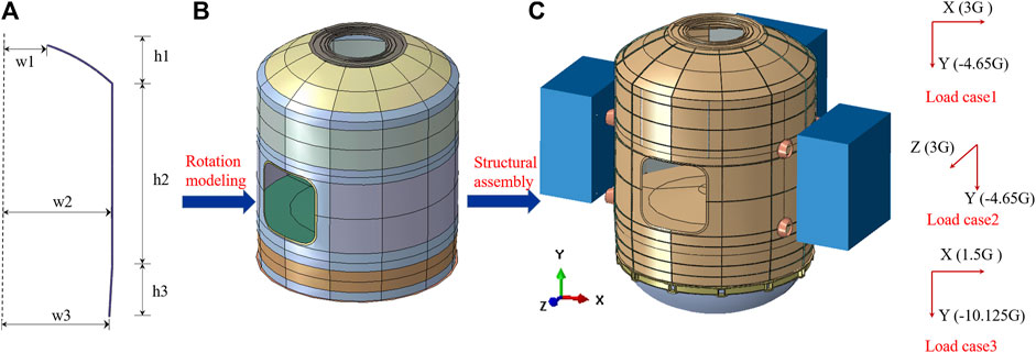
FIGURE 1. Schematic diagram of the sealed cabin structure: (A) axial symmetry model; (B) three-dimensional model; (C) the model for finite element analysis.
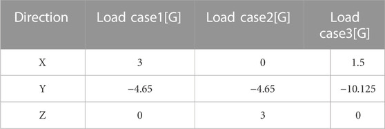
TABLE 1. Loading conditions of the numerical analysis.
The sealed cabin primarily experiences inertial loads during the launch and landing stages. Therefore, three different loading conditions (transverse and longitudinal) are selected as the design loads, which is displayed in Table 1. Taking into account the structural design requirements, a safety factor of 1.5 is applied to the actual loads for the structural design. In Table 1, the “Y" direction represents the axial direction of the sealed cabin. The boundary conditions are set at the corresponding positions of the 12 bolt holes on the bottom frame under fixed support, constraining all six degrees of freedom.
2.2 Topology optimization
First, a finite element model is established based on the sealed cabin shell model. The topology optimization model was built using S4 shell elements in Hypermesh. The design domain is set as the reinforcement area of the sealed compartment. The skin thickness is set to 1.5mm, and the reinforcement thickness is set to 18.5 mm, with a total height of 20 mm. The optimization objective is to minimize the weighted strain energy of the model under three working conditions, using the Solid Isotropic Material with Penalization (SIMP) (Nana et al., 2017; Fei et al., 2022) material penalization model. The volume fraction constraint is set to 0.3. The formulation of the topology optimization can be written as follows,
where ke represents the stiffness matrix of the element e, ue represents the nodal displacement vector of element e,
The topology optimization results are presented in Figure 2. From the results, it can be observed that due to the higher magnitude of the longitudinal overload, the optimization retains more material in the longitudinal direction, forming a longitudinal bar pattern. At the same time, since the optimization objective is to minimize the weighted sum of strain energy under multiple working conditions, the presence of coupled transverse and longitudinal loads results in an oblique arrangement of stiffeners.
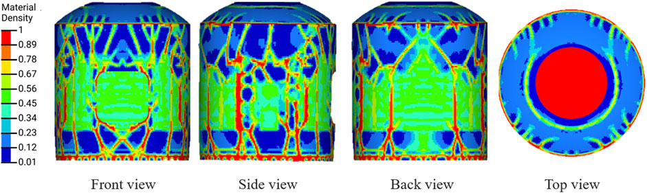
FIGURE 2. Schematic diagram of the topology optimization results for the sealed cabin.
2.3 Model reconstruction and finite element analysis
Based on the results of the optimization analysis, a reassessment of the model after 3D geometric reconstruction is conducted. The reconstructed sealed cabin model, including 102439 S4 elements and 1383 S3 elements, was also constructed using shell elements. To ensure the rationality and correctness of the whole cabin finite element model, the modeling process drew heavily from the modeling experience of platforms (Hao et al., 2016; Amroune et al., 2022) such as the core module of the space station and satellites, inheriting most of the modeling methods. The overall wall panel structure is modeled using shell elements, while the various connecting frames are modeled using beam elements.
To facilitate the reconstruction of the topology optimization results, the mesh-mapping technique is established for modeling the optimized sealed cabin structure. Firstly, a target domain model is established based on the dimensions of the space seal cabin structure, and a mesh is created. The finite element model of the target domain is then flattened to obtain a simple flat plate model, which served as the background domain. Since the background domain is obtained by flattening the target domain, the number of finite element nodes in both domains is the same, amounting to a total of 3,267. The Radial Basis Function (RBF) surrogate model (Shi et al., 2015a; Shi et al., 2015b) is used to train the position coordinates relationship between the finite element nodes of the background domain and the target domain. The general expression of RBF can be illustrated as follows:
where r is an n-dimensional vector of variables, ri is the vector of design variables at the ith sampling point, ‖r-ri‖ is the Euclidean distance, Nm is the total number of selected data points, ɸ is a radial function and αi is the unknown coefficient of the ith RBF node.
In this section, the Wendland C2 function is selected as the radial function, and the expression is:
By considering the different input and output finite element nodes, both forward and reverse mapping relationships could be obtained. The schematic diagram of the mesh-mapping technique is shown in Figure 3.
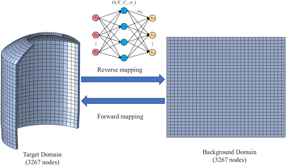
FIGURE 3. Schematic diagram of the mesh-mapping technique based on the RBF model.
The reverse mapping relationship is defined as follows: the input of the RBF model is the coordinates of the finite element nodes in the target domain, and the output is the coordinates of the finite element nodes in the background domain. The forward mapping relationship is defined as follows: the input of the RBF model is the coordinates of the finite element nodes in the background domain, and the output is the coordinates of the finite element nodes in the target domain. For the sealed cabin structure, the optimization results are obtained based on the topology optimization, which provided the material distribution with a density greater than 0.5. Due to the symmetrical structure of the lander, only half of the results are used for finite element modeling. With the previously established mapping relationship, the surface topology optimization results are reverse-mapped to obtain plane results. Based on the plane topology optimization results, feature extraction is performed considering both the topology optimization results and the actual structural load-bearing requirements. The results are fine-tuned to establish the plane stiffened model. Using the forward mapping relationship, a surface stiffened structure is constructed, and finally, the sealed cabin stiffened shell model is established. The specific flowchart is shown in Figure 4.
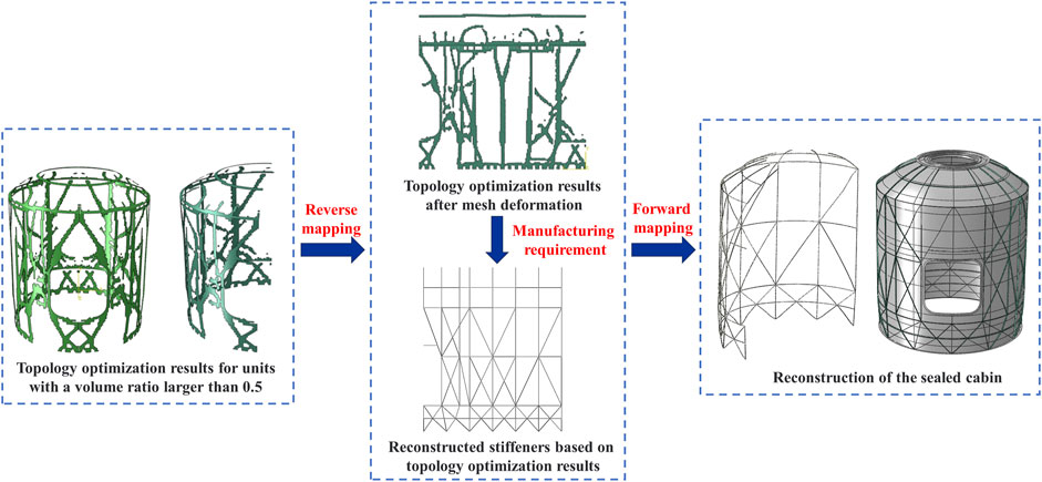
FIGURE 4. Schematic diagram of the sealed cabin reconstruction based on mesh-mapping technique.
For conservative analysis of the preliminary design, the cabin door is kept fully open, and the door frame is reinforced using beam elements. The weight of the docking mechanism is applied to its corresponding connecting frame as non-structural mass. The external instrument equipment platform is modeled using shell elements and suspended on the side wall panels using multi-point constraints (MPC). The internal instrument equipment is applied to the cabin walls as non-structural mass. The total mass of the finite element model of the sealed cabin is 9,400 kg. Figure 5.
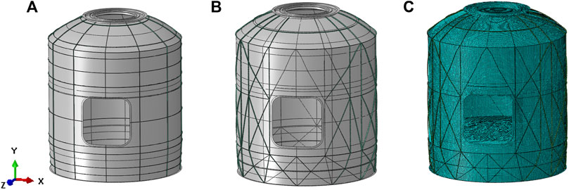
FIGURE 5. Schematic diagram of the sealed cabin structure: (A) initial configuration; (B) the optimized configuration; (C) finite element model of the optimized configuration.
During the ground stage, the pressure inside and outside the entire cabin is balanced. At the start of the launch, the pressure inside the fairing is 1.0 atm. As the altitude increases during the launch, the pressure inside the fairing decreases. The sealed cabin is connected to the fairing through a pressure relief device, causing the pressure to gradually decrease until it reaches a certain pressure value. A maximum pressure difference of 60 kPa between the inside and outside of the fairing is selected to calculate the upper limit of the internal pressure loading on the spacecraft, which would be used as the design condition. Taking a safety factor of 1.5 into consideration, the stress distribution within the structure under an internal pressure of 90 kPa is shown in Figure 6. The majority of the structure experiences stress levels below 220 MPa, with only slightly higher stress levels observed at the cabin door. After conducting finite element analysis, it is found that the optimized configuration meets the strength requirements. The skin mass of aerospace sealed cabin is 221 kg. The mass of the initial layout design of the stiffeners is 106 kg. After topology optimization, the mass of the stiffeners is reduced to 50 kg, resulting in a weight reduction of 52.8% compared to the initial design. The overall mass of the sealed cabin is reduced by 17.1% after optimization compared to the initial design. Detailed information of the comparion of the initial design and the optimized design is displayed in Table 2.
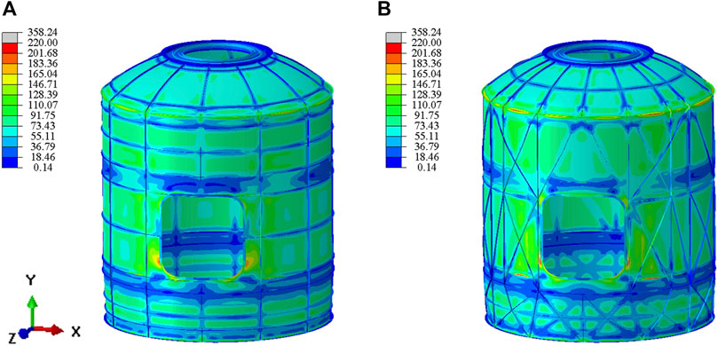
FIGURE 6. The stress distribution diagram of the sealed cabin: (A) initial design; (B) optimized design.
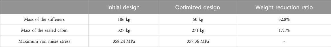
TABLE 2. Comparison between the initial design and the optimized design.
3 Experimental validation of the sealed cabin
In order to validate the tightness, reliability of the manufacturing and strength of the weld, the hydraulic test and airtight test of the sealed cabin structure are carried out in this section. In section 3.1, the concrete implementation steps, results and discussion of the hydrostatic test of the sealed cabin are presented. In Section 3.2, the implementation steps and test results of the airtight test of the sealed cabin are introduced.
3.1 Hydrostatic test of the sealed cabin
In this section, the hydraulic test of the sealed cabin structure is carried out, aiming to assess the bearing ability of the welded structure and the screw sealing parts under the internal pressure loading condition. In addition, the hydraulic test also evaluates the strength of the welded seam of the sealed cabin shell structure and validates the reliability of the welding process.
Based on the innovative configuration obtained in Section 2, the sealed cabin structure is constructed and is shown in Figure 7. In the hydraulic test, DH5921 dynamic signal acquisition and analysis system is used to measure the structural strain. The strain measurement accuracy is ±0.5% and the measuring range is ±20000 με. The number of strain measuring points arranged on the structure of the sealed cabin is 270, and their distribution positions are shown in Figure 8. Unidirectional strain gauges are used for the stiffened structure, and triaxial strain rosettes are used for the other regions. All of the strain measuring points are arranged on the outer surface of the sealed cabin structure, mainly including the front frame, front connection frame, middle connection frame, rear connection frame, rear frame, reinforcement stringer, root corner box and other key positions where the stress may be large.
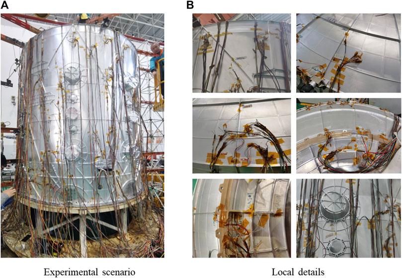
FIGURE 7. Hydrostatic test of the sealed cabin door: (A) experimental scenario; (B) local details.
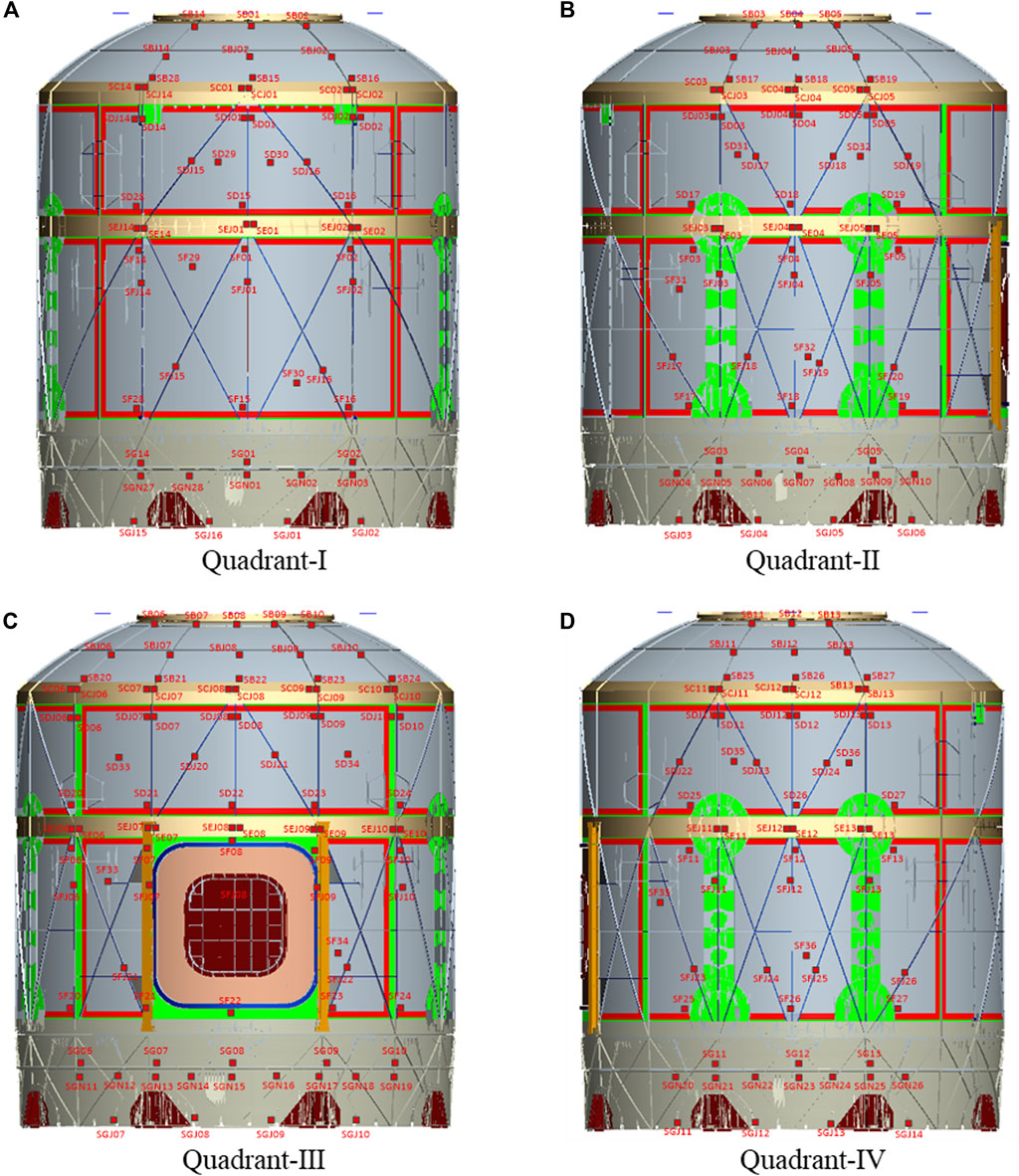
FIGURE 8. Positions of the strain gauges distributed on the sealed cabin: (A) quadrant-Ⅰ; (B) quadrant-Ⅱ; (C) quadrant-Ⅲ; (D) quadrant-Ⅳ.
The hydraulic test of the sealed cabin structure is loaded according to Figure 9, including 10 loading stages and 10 unloading stages. When the experiment starts, the pressure gauge on the process cover of the previous cabin door shall prevail. Before water injection, the measuring system shall be adjusted to 0, and the condition of the cabin filled with water shall be regarded as level 1. The pressure is stabilized for 3 min per stage, and the pressure is stabilized for 30 min when the pressure is at its maximum. After the loading process is finished, the unloading process continues. During each stage of the hydraulic test, the strain of the structure is measured and the data is collected according to the analysis system.
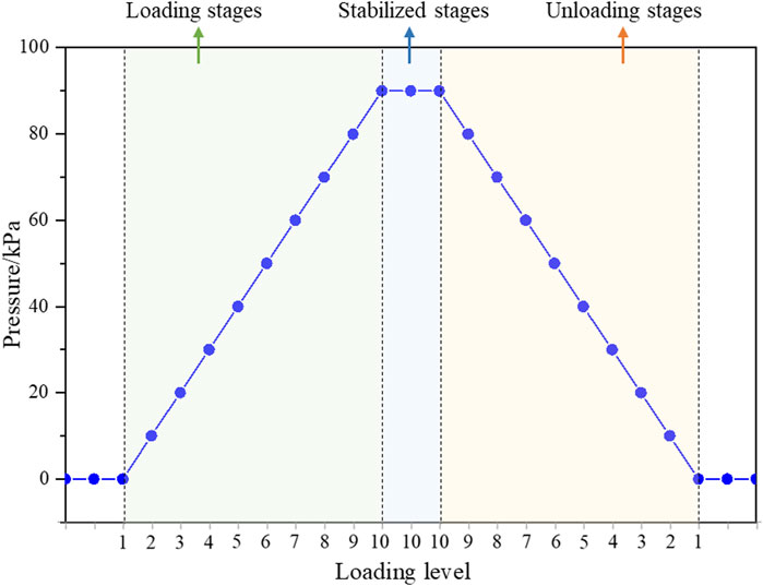
FIGURE 9. Loading sequence of the hydrostatic test.
Through the hydraulic test of the sealed cabin structure, the strain results of the structure under different loading stages can be obtained. The change of the principal strain corresponding to the measuring points at several key positions under loading and unloading relief is shown in Table 3. As shown in Table 3, only the strain values of sensors in the SC and SD regions were found to be relatively large during the loading process. The strain measurements at various points in the SC and SD regions during the loading and unloading processes can be seen in Figure 10. It can be observed from Figure 10 that as the pressure inside the chamber is gradually loaded and unloaded, the main strain at each measurement point exhibits a linear distribution, and the strain variation trends during loading and unloading are similar for each measurement point. It can be found from the table that the values of residual strain of each measuring point is small, and all of which are less than 20 με. In addition, the whole loading process is carried out smoothly, and there is no leakage phenomenon during the experiment.
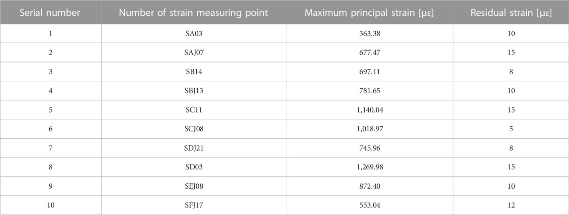
TABLE 3. Typical strain measuring points of the sealed cabin of the hydrostatic test.
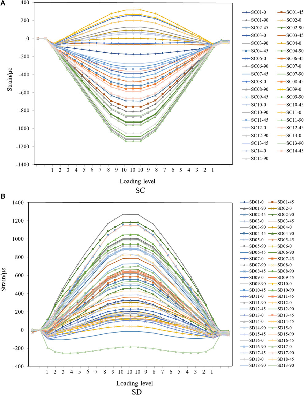
FIGURE 10. Variation of the strains with different loading condition in the hydrostatic test: (A) the strain gauges in the SD region; (B) the strain gauges in the SD region.
Results of the hydrostatic test and strain measurement in the sealed cabin demonstrate that the structure does not yield during the experiment. The low strain level around the weld indicates that the weld meets the requirements of strength and tightness. In summary, the hydraulic test validates that the weld and screw seal design of the sealed cabin structure has the ability to withstand the internal pressure load, and the structural design is reasonable and the sealing performance is qualified.
3.2 Airtight test of the sealed cabin
Sealing performance is also an important function index of the spacecraft, which is of great significance to the life safety of astronauts and the service life of equipment (Batina, 1990). In this section, the airtight test will be carried out to evaluate the airtight performance of the sealed cabin structure. Moreover, the airtight performance of the weld and screw seal parts will also be tested, and the leakage rate of the airtight shell structure would be calculated to check whether the structure of the sealed cabin meets the design requirements (Neyers et al., 2000; Ghosh and Nag, 2001; Gutmann, 2001; Bendsøe et al., 2004; Krishna et al., 2017; Xianwen et al., 2022; Lei et al., 2023).
First, the sealed cabin structure is placed vertically in the collection chamber, and a mixture of helium and air is filled into the cabin, aiming to make the pressure difference between the inside and outside of the cabin maintained at 0.6 atmospheric pressure. At this moment, the absolute pressure inside the capsule is 1.6 atm, namely, 160 kPa. The collection room is a normal atmospheric environment, the proportion of helium gas is about 50%. Then, the pressure of the sealed cabin is then kept constant for 24 h. Finally, the leakage rate of the cabin is calculated by measuring the concentration of helium in the collection chamber with a helium mass spectrometer. The allowable leakage rate of the sealed cabin structure in this experiment is not more than 1.94 × 10E-2 Pa·m3/s.
The results of the airtight test of the sealed cabin structure are shown in Table 4. The measured leakage rate is 1.07 × 10E-2 Pa·m3/s, which is less than 1.94 × 10E-2 Pa·m3/s. The results of leakage rate measurement illustrate that the sealing performance of the sealed cabin structure is qualified and meets the target requirements, which also demonstrates the practicability and reliability of the structural design and processing.
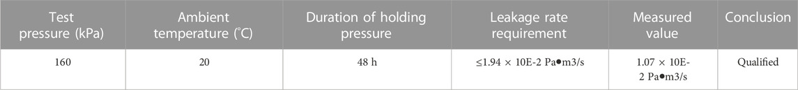
TABLE 4. Results of the airtight test of the sealed cabin structure.
4 Conclusion
Aiming to carry out the lightweight design for the sealed cabins, a novel layout design framework for the integrally stiffened shells under complex loading conditions is developed, and intelligent stiffener configuration of integrally stiffened shells and experimental validation are carried out in this work. The topology optimization method is employed to obtain an innovative layout design firstly, and then the mesh-mapping technique is utilized to assist the reconstruction and modeling process of the optimization result. Compared with the initial design, the weight of the optimized configuration of the integrally stiffened shell reduces by 17.1%, demonstrating excellent lightweight design effects. Moreover, a sealed cabin with the size of 2800-mm-diameter and 3300-mm-height is constructed based on the optimization and numerical analysis result. The hydraulic test validates that the weld and screw seal design of the sealed cabin structure has the ability to withstand the internal pressure load, and the structural design is reasonable and the sealing performance is qualified. The measured leakage rate is 1.07 × 10E-2 Pa·m3/s of the airtight test which is within the specified range (1.94 × 10E-2 Pa·m3/s), illustrating that the sealing performance of the sealed cabin structure meets the target requirements. To sum up, the results of the hydrostatic test and airtight test validate the applicability and effectiveness of the optimized configuration.
In the future study, the static experiment will be carried out to further test the bearing capability of the optimized configuration of the sealed cabin under the overload conditions.
Data availability statement
The raw data supporting the conclusion of this article will be made available by the authors, without undue reservation.
Author contributions
CZ: Conceptualization, Formal analysis, Investigation, Methodology, Visualization, Writing–original draft. LH: Writing–original draft, Software, Validation. LZ: Validation, Writing–original draft, Formal analysis. CY: Writing–original draft, Methodology. CJ: Writing–original draft. LX: Conceptualization, Formal analysis, Writing–review and editing.
Funding
The authors declare that no financial support was received for the research, authorship, and/or publication of this article.
Conflict of interest
The authors declare that the research was conducted in the absence of any commercial or financial relationships that could be construed as a potential conflict of interest.
Publisher’s note
All claims expressed in this article are solely those of the authors and do not necessarily represent those of their affiliated organizations, or those of the publisher, the editors and the reviewers. Any product that may be evaluated in this article, or claim that may be made by its manufacturer, is not guaranteed or endorsed by the publisher.
References
Amroune, A., Cuillière, J. C., and François, V. (2022). Automated lofting-based reconstruction of CAD models from 3D topology optimization results. Computer-Aided Des. 145, 103183. doi:10.1016/j.cad.2021.103183
Batina, J. T. (1990). Unsteady Euler airfoil solutions using unstructured dynamic meshes. AIAA J. 28 (8), 1381–1388. doi:10.2514/3.25229
Bendsøe, M. P., Sigmund, O., and Bendsøe, M. P. (2004). Topology optimization by distribution of isotropic material. Topol. Optim. Theory, Methods, Appl. 2004, 1–69.
Boggiatto, D., and Sferlazzo, A. (1999). The family of Italian pressurized structures for the international space station scenario. Acta Astronaut. 44 (7-12), 553–560. doi:10.1016/s0094-5765(99)00084-3
Duc, N. D., Kim, S. E., Manh, D. T., and Nguyen, P. D. (2020). Effect of eccentrically oblique stiffeners and temperature on the nonlinear static and dynamic response of S-FGM cylindrical panels. Thin-Walled Struct. 146, 106438. doi:10.1016/j.tws.2019.106438
Fei, C., Wen, J., Han, L., Huang, B., and Yan, C. (2022). Optimizable image segmentation method with superpixels and feature migration for aerospace structures. Aerospace 9 (8), 465. doi:10.3390/aerospace9080465
Feng, S., Zhang, W., Meng, L., Xu, Z., and Chen, L. (2021). Stiffener layout optimization of shell structures with B-spline parameterization method. Struct. Multidiscip. Optim. 63, 2637–2651. doi:10.1007/s00158-021-02873-8
Ghosh, J., and Nag, A. (2001). “An overview of radial basis function networks,” in Radial basis function networks 2: New advances in design. Editors R. J. Howlett, and L. C. Jain (Berlin, Germany: Springer), 1–36.
Gutmann, H. M. (2001). A radial basis function method for global optimization. J. Glob. Optim. 19 (3), 201–227. doi:10.1023/a:1011255519438
Hao, P., Wang, B., Tian, K., Li, G., Du, K., and Niu, F. (2016). Efficient optimization of cylindrical stiffened shells with reinforced cutouts by curvilinear stiffeners. AIAA J. 54 (1), 1350–1363. doi:10.2514/1.j054445
Hassani, B., Tavakkoli, S. M., and Ghasemnejad, H. (2013). Simultaneous shape and topology optimization of shell structures. Struct. Multidiscip. Optim. 48, 221–233. doi:10.1007/s00158-013-0894-9
Ho-Nguyen-Tan, T., and Kim, H. G. (2022). An efficient method for shape and topology optimization of shell structures. Struct. Multidiscip. Optim. 65 (4), 119. doi:10.1007/s00158-022-03213-0
Hopson, G. D., and Grant, R. L. (1993). Pressurized modules for space station freedom. Space Technol. Industrial Commer. Appl. 13 (3), 231–243.
Krishna, L. S. R., Mahesh, N., and Sateesh, N. (2017). Topology optimization using solid isotropic material with penalization technique for additive manufacturing. Mater. today Proc. 4 (2), 1414–1422. doi:10.1016/j.matpr.2017.01.163
Lee, Y. S., and Kim, Y. W. (1998). Vibration analysis of rotating composite cylindrical shells with orthogonal stiffeners. Comput. Struct. 69 (2), 271–281. doi:10.1016/s0045-7949(97)00047-3
Lei, J., Jia, D., Bai, M., Feng, Y., and Li, X. (2023). Research and development of the Tianzhou cargo spacecraft. Space Sci. Technol. 3, 0006. doi:10.34133/space.0006
Liu, H., Li, B., Yang, Z., and Hong, J. (2017). Topology optimization of stiffened plate/shell structures based on adaptive morphogenesis algorithm. J. Manuf. Syst. 43, 375–384. doi:10.1016/j.jmsy.2017.02.002
Nana, A., Cuillière, J. C., and Francois, V. (2017). Automatic reconstruction of beam structures from 3D topology optimization results. Comput. Struct. 189, 62–82. doi:10.1016/j.compstruc.2017.04.018
Neyers, B. T., Adams, J. T., and Stoutenborough, T. S. (2000). “Aerospace leak test requirements,” in 36th AIAA/ASME/SAE/ASEE Joint Propulsion Conference and Exhibit (Washington, DC: AIAA).
Quan, T. Q., Cuong, N. H., and Duc, N. D. (2019). Nonlinear buckling and post-buckling of eccentrically oblique stiffened sandwich functionally graded double curved shallow shells. Aerosp. Sci. Technol. 90, 169–180. doi:10.1016/j.ast.2019.04.037
Rahimi, G. H., Zandi, M., and Rasouli, S. F. (2013). Analysis of the effect of stiffener profile on buckling strength in composite isogrid stiffened shell under axial loading. Aerosp. Sci. Technol. 24 (1), 198–203. doi:10.1016/j.ast.2011.11.007
Semmani, A., Sereir, Z., and Hamou, Y. (2020). Analysis and optimization of composite kagome grid panels subjected to the low velocity impact. J. Dyn. Behav. Mater. 6 (3), 287–302. doi:10.1007/s40870-020-00243-x
Shi, P., Kapania, R. K., and Dong, C. (2015b). “Free vibration analysis of curvilinearly stiffened cylindrical shells,” in 56th AIAA/ASCE/AHS/ASC structures, structural dynamics, and materials conference (Florida: AIAA, Reston).
Shi, P., Kapania, R. K., and Dong, C. Y. (2015a). Free vibration of curvilinearly stiffened shallow shells. J. Vib. Acoust. 137 (3), 031006. doi:10.1115/1.4029360
Shimoda, M., Umemura, M., Al Ali, M., and Tsukihara, R. (2023). Shape and topology optimization method for fiber placement design of CFRP plate and shell structures. Compos. Struct. 309, 116729. doi:10.1016/j.compstruct.2023.116729
Van Dung, D., and Chan, D. Q. (2017). Analytical investigation on mechanical buckling of FGM truncated conical shells reinforced by orthogonal stiffeners based on FSDT. Compos. Struct. 159, 827–841. doi:10.1016/j.compstruct.2016.10.006
Wang, D., and Abdalla, M. M. (2015). Global and local buckling analysis of grid-stiffened composite panels. Compos. Struct. 119, 767–776. doi:10.1016/j.compstruct.2014.09.050
Xianwen, N., Yuying, W., Jing, P., Gao, Z., Fan, J., and Dong, Z. (2022). Design and implementation of the integrated thermal control system for Chang’E− 5 lunar module. Acta Astronaut. 200, 188–195. doi:10.1016/j.actaastro.2022.08.005
Zhang, W., Wang, C., Zhou, L., and Gao, T. (2022). Three-dimensional topology optimization considering overhang constraints with B-spline parameterization. Comput. Struct. 269, 106823. doi:10.1016/j.compstruc.2022.106823
Zhou, Y., Zhu, J., Zhan, H., Zhang, W., and Gu, Y. (2021). A bio-inspired B-spline offset feature for structural topology optimization. Comput. Methods Appl. Mech. Eng. 386, 114081. doi:10.1016/j.cma.2021.114081
Keywords: sealed cabin, lightweight design, hydrostatic test, airtight test, integrally stiffened shells
Citation: Zhizhong C, Hongqing L, Zengcong L, Yan C, Jie C and Xiaoqi L (2023) Structural lightweight design and experimental validation for aerospace sealed cabin. Front. Mech. Eng 9:1265734. doi: 10.3389/fmech.2023.1265734
Received: 23 July 2023; Accepted: 28 August 2023;
Published: 08 September 2023.
Edited by:
Li Li, Huazhong University of Science and Technology, ChinaReviewed by:
Kadir Gunaydin, General Electric, United StatesZhe Ding, Wuhan University of Science and Technology, China
Copyright © 2023 Zhizhong, Hongqing, Zengcong, Yan, Jie and Xiaoqi. This is an open-access article distributed under the terms of the Creative Commons Attribution License (CC BY). The use, distribution or reproduction in other forums is permitted, provided the original author(s) and the copyright owner(s) are credited and that the original publication in this journal is cited, in accordance with accepted academic practice. No use, distribution or reproduction is permitted which does not comply with these terms.
*Correspondence: Li Xiaoqi, 1657663815@qq.com