A review of beamforming microstrip patch antenna array for future 5G/6G networks
 Muhammad Asfar Saeed*
  Augustine O. Nwajana
- School of Electronics, University of Greenwich, London, United Kingdom
With the increase in demand for high data rates and high bandwidth because of multiple users all over the globe, the technology has moved toward the next-generation of wireless communication. This rapid advancement of wireless communication technologies has led to the emergence of 5G networks, which promise significantly higher data rates, lower latency, and enhanced connectivity. Researchers believe that five essential techniques can enable 5G. Beamforming is one of those essentials, as it plays a vital role in achieving reliable and high-capacity communication. This review article portrays a comprehensive analysis of the 5G beamformer Microstrip Patch Antenna array techniques for communication systems. The paper comprises of a deep overview of the fundamental concepts and principles of beamforming, including analog, hybrid, and digital beamforming techniques. It explores the advantages and disadvantages of each approach and discusses their suitability for 5G applications. An in-depth examination of various beamforming techniques employed in 5G, encompassing traditional beamforming, massive Multiple-Input-Multiple-Output beamforming, hybrid beamforming, and adaptive beamforming. The discussion encompasses the strengths, weaknesses, and performance trade-offs of each technique, along with their applicability in diverse deployment scenarios and applications. The review of multiple couplers that are used for the feeding of the antenna is discussed with included hybrid coupler, Wilkinson power divider, branch line coupler, and butler matrix in beamformer smart antenna for 5G/6G communications. Numerous beamforming techniques are compared based on their merits, demerits, and applications. Moreover, the dielectric substrate utilized to design the beamformer was also reviewed. The findings presented in this paper serve as a valuable resource for the researcher, scholars, and engineers working in the field of 5G wireless communications and antenna designing, facilitating the development and deployment of efficient and robust beamforming solutions for future 5G networks.
1 Introduction
Around the globe, the increase in high data rates and compact electronic devices are dramatically increasing and the technology emerging beyond the fifth generation (5G) has started in different areas of the modern domain (Wang et al., 2017; Guo and Ziolkowsk, 2021). 5G consists of drastically enhanced high data rates, low latency, massive connectivity, and game-changing new applications (Ahmed et al., 2018). Five essential technologies can enable the fifth generation which is dependent upon small cells, beamforming, full-duplex, multiple input multiple output MIMO, and mm-Wave. Beamforming, MIMO, and mm-waves play a vital role in enabling 5G. Furthermore, mm-waves can be generated using the radiator responsible for propagating EM waves into the air, for enhanced connectivity, an antenna is a key element in the communication system as the rapid expansion of technology in modern radio systems, such as those meant for 5G networks operating at sub-centimeter and millimetre-wave frequencies (Yu et al., 2018). An antenna has the essential responsibility of converting electrical signals into electromagnetic waves, and vice versa. When an alternating electrical signal is applied to an antenna, it creates an oscillating electric and magnetic field. This generates electromagnetic waves which radiate out from the antenna into space. In the literature, different types of antennas are investigated. Dipole Antenna: A dipole antenna is the simplest category of antenna and consists of two conductive components, often in the form of wires or metal rods, placed parallel to each other. Dipole antennas are commonly utilized for radio and television transmissions (Patil and Popalghat, 2016). Loop Antenna: A loop antenna is a simple antenna that consists of a loop of wire or metal rod. Loop antennas are commonly used for radio reception in portable devices such as AM/FM radios. Yagi Antenna: A Yagi antenna is a directional antenna consisting of several elements arranged in a specific pattern (Huitema and Monediere, 2012). Yagi antennas are generally employed for television receiving and transmission, as well as in wireless communication systems (Saeed and Nwajana, 2021). Patch Antenna: A patch antenna is a flat, rectangular antenna that is regularly exploited in wireless transmission systems, such as Wi-Fi networks (Yang et al., 2017). Parabolic Antenna: A parabolic antenna is a dish-shaped antenna that is commonly used in satellite communication systems and radar systems (Patil and Popalghat, 2016). A microstrip patch transmitter is generally employed in modern wireless communication systems, such as cellular networks, satellite communication, (Global positing system) GPS, and Wireless Local Area Networks (WLAN). It can be easily structured in diverse dimensions and shapes. Beam steering plays a crucial role in 5G communication systems. Beam steering allows for focused and directed signal transmission toward specific users or areas. By dynamically adjusting the beam direction, the signal can be concentrated where it is needed, resulting in improved signal quality, reduced interference, and a higher signal-to-noise ratio (SNR). This leads to better overall transmission performance and higher data rates. It enhances the coverage and range by targeted signal transmission, extending the coverage and range of the 5G network. By focusing the signal in a specific direction, beamforming compensates for path loss and signal attenuation, enabling better coverage in both urban and rural areas. This is particularly important for mm-Wave frequencies, which have a shorter range but higher data rates (Guo and Ziolkowsk, 2021). Beam steering in 5G communication systems provides benefits such as enhanced signal quality, increased capacity and throughput, extended coverage, interference mitigation, energy efficiency, and mobility support. These advantages contribute to improved network performance, user experience, and the ability to meet the growing demands of diverse 5G applications and services. Researchers have investigated various methods of achieving beam steering and proposed a microstrip patch antenna suitable candidate to fulfil the requirements of future 5G because of its advanced feature. Microstrip patch antenna can be easily integrated into compact and low-profile devices. Their flat geometry allows for easy fabrication, integration with other components, and deployment in various applications (Cheng et al., 2017). Previously microstrip antennas were frequently employed as the radiating elements in phased array antenna systems. Phased arrays comprise multiple antenna elements assembled in a specific pattern and connected to a phase-shifting network. By controlling the phase of the signals fed to each antenna element, beam steering can be achieved (Jiang et al., 2018). Microstrip antennas can be designed using a combination of conductive radiating patches and a dielectric substrate. By adjusting the dimensions of the patches and the dielectric properties of the substrate, the antenna can be designed to exhibit specific radiation patterns. This allows for control over the direction of the emitted radiation and facilitates beam steering capabilities (Li and Luk, 2020). Moreover, their simple planar structure and the use of commonly available materials make them relatively inexpensive compared to other antenna types (Elfatimi et al., 2018). A microstrip patch antenna plays an essential role in achieving directional and steerable radiation patterns, enabling beam steering in various communication systems. Beam steering is a fundamental concept in antenna technology that involves controlling the direction of the radiated or received electromagnetic waves. It allows for the adjustment of the antenna radiation pattern to focus the energy in a particular direction or toward a specific target. In the context of 5G communication systems, beam steering plays a fundamental role in refining performance and addressing the unique challenges of next-generation wireless networks. To address these challenges, a microstrip antenna is believed to provide a viable solution. Microstrip antennas are a type of printed antenna that operates based on the principles of microstrip transmission lines. They comprise a radiating element placed on top of a dielectric material utilized as a substrate in between the ground and radiating patches, with a ground plane stuck on the other side of the antenna design as shown in Figure 1. The well-known equations for Microstrip patch antennas are the following:
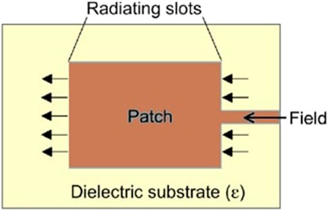
FIGURE 1. Microstrip patch antenna top view.
The width of the radiating patch was determined using Equation 1.
The length of the radiating element was computed using Equation (2)
The effective dielectric Constant of the radiating antenna was determined using Equation (3)
Extension in the length ΔL:
The effective length of the antenna is calculated:
Length of substrate:
Width of substrate:
Microstrip antennas can be fed using various techniques, including edge feeding, insect feeding, or aperture coupling. These feeding techniques allow for control over the phase and amplitude of the current distribution on the patch, which influences the radiation pattern and facilitates beam steering (Wang et al., 2022). Microstrip antennas are commonly used in phased array configurations for beam steering applications. Multiple microstrip antenna elements can be arranged in a specific geometry and fed with different phase shifts. By adjusting the phase distribution, the resulting interference pattern can be directed in a desired direction, achieving beam steering capabilities. Digital beamforming involves Multiple-Input-Multiple-Output (MIMO) for signal processing which is a highly adaptable approach for generating separate steerable multiple beams (Cao et al., 2021). In literature researchers (Cao et al., 2021) (Liu et al., 2022) (Liao et al., 2015) have accomplished beam steering using array antenna technology. Digital beamforming consists of massive antenna arrays that operate as a powerful tool to fulfil some of the most difficult required features of forthcoming wireless transmission networks, specifically in rich spreading conditions. In contrast, this approach generally leads to high power utilization, and power losses which also impact the hardware cost, which prevents its use in many applications such as large-scale low-cost (Ashok and Sudha, 2019). Similarly in literature, many techniques have been utilized (Liao et al., 2015; Ali et al., 2017; Ashok and Sudha, 2019) to achieve the steerable beam employing the microstrip patch antenna arrays. These techniques have some limitations. To improve the coverage of the antenna an array system is occupied in which antenna radiating elements are increased according to the separation between the radiating elements to achieve constructive interference of the propagated signals (Aluigi et al., 2018). Additionally, researchers have utilized a 16 × 16 antenna array with a metal wall as a reflector and with similarly shared coupling in between the resonating patches is responsible for wide beamforming in linear and phased array (Elfatimi et al., 2018). Pattern reconfigurable techniques is utilized in the expansion of coverage in (Li et al., 2018) (Li and Luk, 2020). In contrast, some techniques involve the combination of mechanical and electrical methodologies to accomplish beamforming (Cao et al., 2016), in addition to these, multiple layers of dielectric material are also applied to improve the coverage of the beamforming (Li and Luk, 2020) Some of the wideband antenna applications have targeted beamforming by implementing the tightly coupled techniques reported in (Wu et al., 2015). All these methods explored in the literature have accomplished beamforming but have some limitations which are needed to be addressed such as efficiency, gain scanning accuracy, etc., therefore an efficient approach required to achieve a high-gain beamforming antenna. Primarily focused on high-speed mobile broadband, 4G introduced advanced signal processing with LTE technology, enhancing data rates and network efficiency. Significant advancements include millimeter-wave frequencies, massive MIMO, and beamforming, boosting data rates, reducing latency, and enabling diverse applications beyond traditional mobile broadband. In the early stages, 6G envisions terahertz frequencies, AI-driven networks, and advanced beamforming for unprecedented data rates, ultra-low latency, and diverse connectivity supporting emerging technologies like holographic communication and advanced IoT. 4G employed LTE, 5G harnessed advanced MIMO, and beamforming, while 6G explores terahertz signal processing, leveraging machine learning for adaptive and intelligent communication. Each generation has strived for improved spectral efficiency; 4G enhanced broadband, 5G expanded capabilities to connect devices, and 6G aims for highly efficient, adaptable networks supporting a vast array of applications and services.
2 Beam forming antenna array
The commonly used wireless communication systems utilize a single antenna which has a broad radiation pattern radiating in all directions around the radiating element. An antenna array is a collected working of multiple radiating patches that are assembled in a specific pattern to achieve constructive and destructive interference to establish a directed beam in the required direction (Ali et al., 2017). Antennas in an array can be physically connected to each other or be separate and can be used for both transmitting and receiving electromagnetic waves. The directivity of the radiating transmitter can be improved by expanding the dimensions of the radiating element (Aluigi et al., 2018). Beamforming utilizes the antenna array technique to create a directional beam of electromagnetic waves by modifying the amplitude and phase of the signals received by individual receiver element of the array. These signals are merged in a technique that creates a constructive interference resulting in a single beam that can be steered in a specific direction. The beamforming process in an antenna array can be done using either analog, digital techniques or hybrid techniques (Varum et al., 2018). In analog beamforming, the phase and amplitude of the signals received by each transmitter patch are adjusted by applying the analog working mechanism of phase shifters and attenuators. This approach is not suitable for the compact devices used for communication as it expands the dimensions plus weight of the communication device, moreover in some applications, it is difficult to integrate into the circuit (Afzal et al., 2021). There are different types of antenna arrays, including linear arrays, circular arrays, planar arrays, and conformal arrays which are illustrated in Figure 2. Linear arrays consist of a row or column of antennas, while circular arrays are arranged in a circular or annular pattern. Planar arrays are two-dimensional arrays, while conformal arrays are designed to conform to a curved surface. The planar array technique is simple and cost-effective but has limitations in terms of flexibility and beamforming resolution. In digital beamforming, the signal reception of each receiver element is first digitized using analog to discrete and digital processing, these are processed using digital signal processing (DSP) algorithms to alter the amplitude and phase of the received signals (Rivas et al., 2010) shown in Figure 3. This procedure is flexible whereas it offers better beamforming resolution than analog beamforming. The choice of analog or digital beamforming technique depends on the specific application, performance requirements, and cost considerations. Beamforming microstrip patch antenna arrays have numerous advantages over the single radiating elements which include enhanced signal quality increased coverage and interference rejections (Rivas et al., 2010; Cao et al., 2016). It is widely used in multiple applications of wireless communications and satellite communications. Beamforming is a technique in which propagation is directed toward the desired direction and in another direction the signal is cancelled out because of destructive interference. This is accomplished using the FIR finite impulse response filter. Moreover, massive MIMOS systems are also combined with it to improve the overall efficiency of the system (Wang et al., 2018). These are employed for systems such as cellular networks, Wi-Fi networks, and radar systems. In literature, several types of arrays described initially were explored by the researchers to accomplish the beamforming, where a scalable 28 GHz beamforming system for 5G automotive connectivity, based on 2 × 2 TRX beamforming core chips and patch antenna array is presented by (Patterson et al., 2012) the designed antenna is resonating at a frequency of 28 GHz, similarly in other research works to achieve higher gains and contribute to a better communication performance linear array is designed horizontally N and vertically M to accomplish the 5G requirements (Djerafi and Wu, 2012) shown in Figure 4. However, they have some limitation that requires the attention of reinvestigations. The comparison of the described above antenna arrays is explained in Table 1.
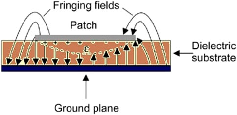
FIGURE 2. Microstrip patch antenna side view.
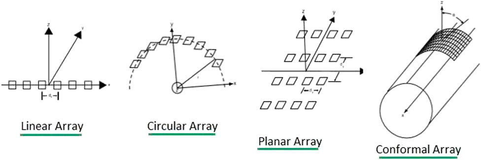
FIGURE 3. 3 Types of microstrip patch antenna array.
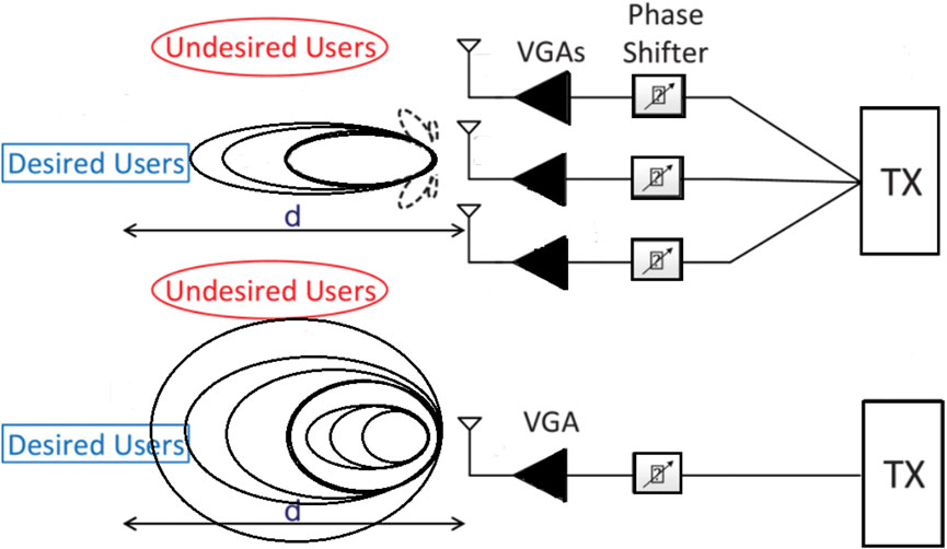
FIGURE 4. Beamforming transmitter radiation towards desired and undesired users.
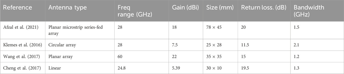
TABLE 1. Comparison between the type of array.
3 Analog beamforming
Analog beamforming is a method utilized in wireless communication systems and radar systems to direct the antenna beam to an exact target by altering the phase and amplitude of the RF signal at the antenna elements. In analog beamforming, the amplitude and phase of the RF signals are coordinated by analog circuits, such as phase shifters and attenuators, which adjust the signal path of each antenna element (Manzillo et al., 2013). Analog beamforming is a method adopted in antenna arrays to steer a steering beam of electromagnetic waves using analog components. The phase shifters are retained to regulate the phase of the radiated signals, while the attenuators are operated to modify the amplitude of the signals. By altering the amplitude plus phase of the signals received by each receiver component, signals are merged to establish a single beam with a specific direction. In literature, researchers have accomplished beamforming utilizing a variety of different techniques (Tekkouk et al., 2015). Phase shifters are devices used to introduce controlled phase shifts to the signals obtained by individual antenna elements in an antenna array. By adjusting the phase shift values, the signals can be combined constructively in the required direction, while causing destructive interference in useless paths. Phase shifters can be implemented using various technologies, such as electronically controlled phase shifters (e.g., varactor diodes) or fixed phase shifters (e.g., transmission lines of different lengths). Moreover, Analog delay lines are used to introduce controlled delays to the signals received by each antenna element. By adjusting the delay values, the signals can be temporally aligned to achieve beam steering. Delay lines can be implemented using transmission lines or other delay elements, and their lengths are carefully selected based on the desired beam steering angles (Jebabli et al., 2022). Similarly, researchers have proposed Hybrid couplers, such as 90-degree and 180-degree couplers, are used in beamforming systems to split and combine signals with specific phase relationships. They are often used in conjunction with phase shifters to create the desired beamforming patterns. Hybrid couplers are passive devices that operate based on the principle of electromagnetic coupling between transmission lines utilized (Rao et al., 2021). On the other hand, literature illustrates the beamforming networks are analog circuits that dis-tribute the signals received by the antenna elements to achieve beam steering. These networks can include power dividers, phase shifters, and other passive components arranged in a specific topology (Eshaghi and Rashidzadeh, 2022). Beamforming networks are designed based on the desired beamforming characteristics and the configuration of the antenna array. Analog beamforming is a simple and low-cost technique compared to digital beamforming, but it has some limitations. Analog beamforming techniques provide simplicity, low latency, and efficient use of power compared to digital beamforming. They are suitable for applications where the total element of the antenna is relatively small, and real-time beamforming is required. However, analog beamforming has limitations in terms of flexibility and adaptability compared to digital beamforming. It is typically used in combination with digital beamforming techniques to achieve hybrid beamforming systems that balance performance and complexity in 5G communication systems. In analogy, beamforming a very famous approach is the butler matrix, where the consumers can shift between the several beams of the antenna. It is widely used in electronic scanning arrays as a MIMO beam-former for the reason of its flexibility and easier for multiple-beam radiators (Tariq et al., 2018). In other applications of UWB ultra-wideband antenna transmitters 4 × 4 butler matrix was designed to operate at 3–9 GHz. The structure of the antenna is hexagonally fabricated on an RT/Duroid 5,880 substrate with an epsilon value of 2.2 whereas the thickness is 0.254 mm, and the loss tangent comprises 0.0009. The fabricated antenna has successfully accomplished a wide range of bandwidth consisting of 6 GHz (Tariq et al., 2018). Additionally, the butler matrix was designed utilizing substrate integrated waveguide technique, the designed model is illustrated in Figure 6 (Butler and Lowe, 1961). RT/Duroid 5,870 is employed as a substrate (Islam MS, Jessy, 2016). The dimension of the model comprises 144 × 146 mm2 which is responsible for achieving a bandwidth of 3 GHz. In some cases of smart antennas which are a combination of hybrid and analog beamforming consist of the DOA direction of signal arrived. In these antennas, as the signal arrives the algorithms decide the direction of arrival which is dependent upon the time delay (Guha et al., 2018). Time delay can be computed using the equation provided.
In the equation above the Vo represents the speed of light whereas, the differential distance is represented by Δr. The signal processing unit and antenna array both are responsible for generating radiation and reception patterns. To overcome limitations such as weak signal strength and directivity the researchers designed an 8 × 8 butler matrix on a Taconic RF35TC substrate (Nwalozie et al., 2013). This design is shown in Figure 4, the epsilon value of the substrate is 3, and it occupies a thickness of 0.127 mm with a loss tangent of 0.0014. In another approach MPA was designed operating at 28 GHz operating frequency on a substrate of Roger’s RO4003, the MPA presented by (Ahmed et al., 2018) consists of 3.7 × 2.8 mm2 whereas the 4 × 4 matrix followed by 1 × 4 linear patches connected responsible for leading the beam to be directed in different directions (Kim et al., 2018) showed in Figure 5. In analog beamforming, some researchers have designed antennas above 50 GHz which are discussed here for 5G applications. A MIMO antenna array is presented in (Rahayu et al., 2019), resonating at a frequency of 60 GHz, the antenna structure contains a 1 × 2 power divider and 2 × 4 radiating MIMO array. RT5880 was employed as a substrate material with a thickness of 0.16 mm The designed model has achieved a high gain of 13.4dBi whereas it has successfully accomplished a markable bandwidth of 4.3 GHz The designed model is shown in Figure 6. On the other hand, a similar MPA microstrip patch antenna array has been reported (Rabbani and Ghafouri-Shiraz, 2017) which consists of a series feed and a parallel feed network with 24 radiating elements integrated on the substrate of RT/Duroid 5,880 with a thickness of 0.127 mm. The designed MPA is responsible of resonating at a high frequency of 61.56 GHz and has achieved a bandwidth of 2.6 GHz. Equation (9) describe the methodology of computing the dimension of the designed MPA (Rabbani and Ghafouri-Shiraz, 2017).
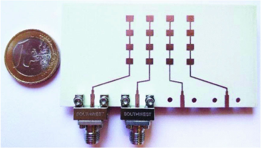
FIGURE 5. The image of the fabricated planar antenna array.
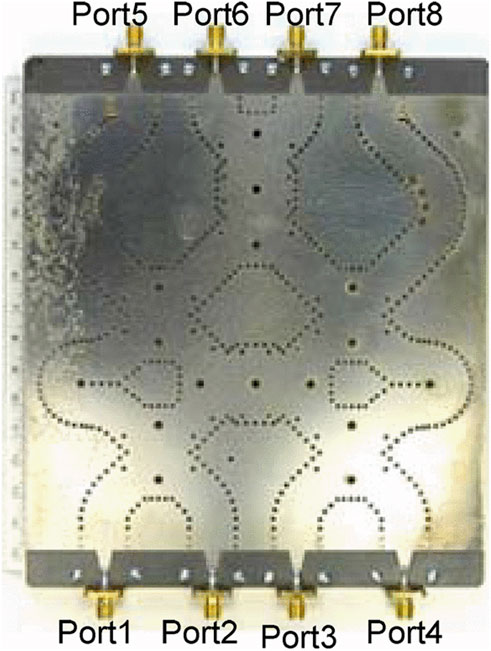
FIGURE 6. 4 × 4 Butler matrix transmission line.
The λ represents the free space and operational wavelength whereas the ΔL is the patch extension. The presented model has achieved an acceptable gain of 19.5 dBi. The design is shown in Figure 7.
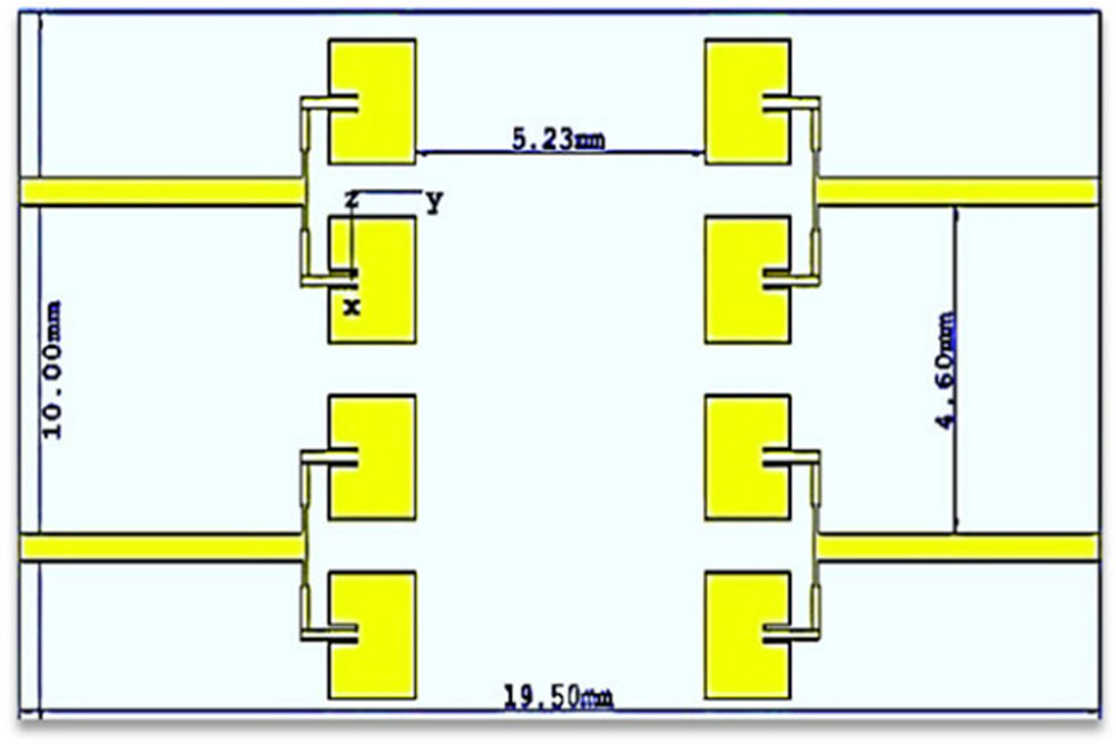
FIGURE 7. MIMO antenna array 2 × 4.
4 Digital beam forming
Digital beamforming is a method utilized in sonar, radar, and transmission techniques to steer the main lobe of the beam in an exact guided target using digital signal processing (DSP) (Lian et al., 2018). In digital beamforming, the propagated waves from multiple radiating elements are merged in a specific way, based on their phase and amplitude, to create a beam in a specific direction and shape. The DSP algorithms use information from the antenna array to calculate the appropriate weights for each antenna element to achieve the desired beam direction and shape. Digital beamforming includes the combination of analog-to-digital converters (ADCs) which are aligned with the digital circuits along and a basic analog system block (Eshaghi and Rashidzadeh, 2022). Digital beamforming methods have some limitations such as low SNR. These drawbacks can be minimized by a zero-forcing approach in which the antenna array is responsible for the constructive and destructive interference of the propagated signals which results in cancelling out of their impact on the overall radiation pattern of the antenna array and delivery of a directed beam (Tariq et al., 2018). Digital beam forming offers advantages to achieve beam forming whereas on the other hand these techniques also have some limitations such as high cost because of this it is not preferred to be a good choice for future 5G and B5G. Digital beamforming typically requires the use of power-hungry digital signal processors (DSPs) or field-programmable gate arrays (FPGAs) to perform the necessary signal-processing operations. These components consume a considerable amount of power, which can be a disadvantage in applications where power utilization should be diminished, such as in mobile devices or energy-constrained environments. In addition, digital beamforming involves complex digital signal processing algorithms and computations. It requires significant processing power and resources to perform the necessary calculations for beamforming, especially in large-scale antenna systems with multiple elements. This computational complexity can increase the hardware requirements and cost of implementing digital beamforming (Guha et al., 2018). To maintain the cost efficiency, identical antenna arrays are employed at the base station for the transmission and reception of the signals. The model designed has a 16-radiating element of antenna arrays, it was polarized both horizontally and vertically operating at the 27.5–28.35 GHz band. The simulated antenna was fabricated using a substrate Rogers 4,350 with an epsilon value of 3.83, a thickness of 0.254 mm, and a loss tangent of 0.0037. The antenna designed covered a size of 30 × 30 mm2. The model accomplished a high gain of 15.65 dBi. The designed model is shown in Figure 8 and Figure 9. The losses incurred during the propagation of waves in the air are calculated using the provided Equation (10).
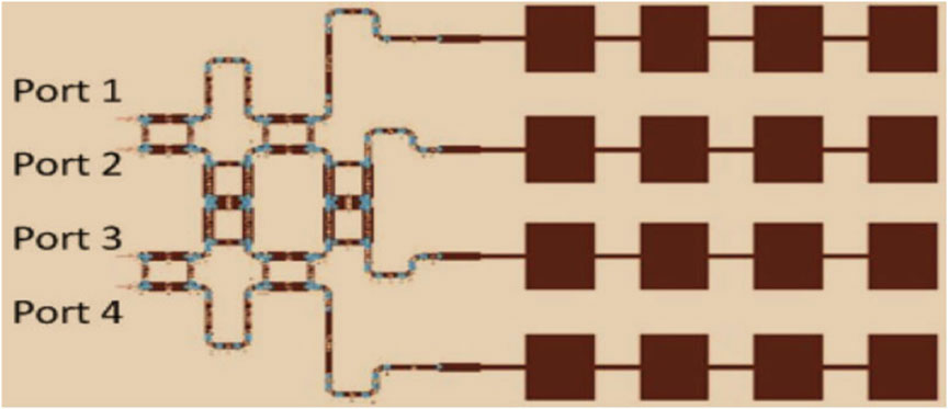
FIGURE 8. 4 × 4 butler matrix beamforming MPA.
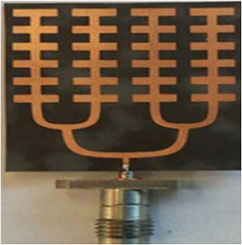
FIGURE 9. 24 elements antenna array.
F, indicates the resonant frequency whereas d, is the separation between the radiating elements.
5 Hybrid beam forming
The hybrid beamforming technique is a mixture of both digital and analog in 5G antenna systems. It offers a trade-off between the advantages of analog beamforming (lower complexity, lower power consumption) and digital beamforming (flexibility, precise beamforming control). The architecture is devised using a technique the antenna array is divided into subarrays, each consisting of multiple antenna elements. Each subarray has an analog beamforming network, which applies phase shifting and gain control to the signals before combining them. The combined signals from different subarrays are then digitized and processed digitally for further beamforming control. Both analog and digital beamforming techniques are merged to perform individual responsibilities. Analog beamforming part of hybrid beamforming is responsible for coarse beamforming control (Nwalozie et al., 2013). It utilizes phase shifters and variable gain amplifiers to steer the main lobe of the propagated signal in a particular direction. Analog beamforming allows for low-latency and low-complexity beamforming, as the control is performed in the analog domain. However, it lacks the fine-grained control and adaptability of digital beamforming. Whereas the digital beamforming part of hybrid beamforming is responsible for fine-grained beamforming control and compensation of imperfections (Nwalozie et al., 2013; Ahmed et al., 2018). The digitized signals from the analog beamforming stage are processed digitally using advanced algorithms and techniques. Digital beamforming provides precise control over the amplitude and phase of the signals, allowing for adaptive beamforming, null steering, and interference cancellation. The overall benefits of hybrid technique include, reduced complexity. It offers reduced complexity and power consumption compared to full digital beamforming, as most of the beamforming control is performed in the analog domain. At the same time, it provides flexibility, adaptability, and improved performance compared to pure analog beamforming. Hybrid beamforming can handle a larger number of antenna elements and supports the high data rates and low latency requirements of 5G networks. The advantages of using hybrid beamforming are reducing cost and increasing the efficiency of the antenna (Kim et al., 2018). Other work contributed to hybrid beam forming consists of orthogonal frequency division multiplexing (OFDM) presented by (Rahayu et al., 2019) designed as a transmitter, which is illustrated in Figure 10. The efficiency of the hybrid beam forming can be calculated using Equation (11).
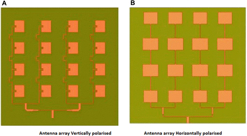
FIGURE 10. (A) Antenna array vertically polarised (B) Antenna array Horizontally polarised.
The subcarriers are denoted by N, ‘m’ is a variable ranging from 0 to ‘N—1’, whereas for the gain adjustments c and w are used for the source and receptor, and the channel matrix is represented by H in the equation. Additional structure of the hybrid beamforming transmitter operating Ns data streams, MIMO encoder and baseband pre-coder, RF chains (NRF), and antenna receiving arrays (Nt) is given in Figure 11 with a minimal alteration forming hybrid beamforming receiver (Rahayu et al., 2019). Similarly, another model presented by (Rao et al., 2021) operates at a frequency range from 23.34 to 28.25 GHz and utilizes the antenna array with a combination of hybrid coupler. The antenna array consists of 10 × 2 radiating elements with 11.52 mm space between the radiating patches. The antenna array was designed using RT/Duroid622 as a substrate, the substrate comprises of epsilon value of 2.9 and a thickness of 0.254 mm. The radiating patches are designed using copper with a thickness of 35 µm. The presented model has achieved a gain of 12. 9dBi.The design is shown in Figure 12. Another approach to beam steering is a defective microstrip structure. A defective microstrip structure (DMS) is a technique used in microstrip antenna design to modify the characteristics of the microstrip transmission line. By introducing periodic or localized defects in the microstrip structure, the propagation properties of the microstrip line can be altered, allowing for various functionalities, including beam steering. An antenna capable of steering the beam is presented in (Ding et al., 2014). The designed antenna consists of three defective microstrip structures along with six defective microstrip power dividers. The dimensions of the antenna are 8 × 2 mm and 10 mm thickness of transmission line. The designed antenna covers a wide bandwidth which is acceptable for WLAN applications, moreover it has the ability to steer the beam −15 to +15. Figure 13 shows the antenna proposed in (Ding et al., 2014). Similarly, a Yagi Uda antenna has been presented by (Issa et al., 2019) this antenna comprises 30 × 30 mm in length and width. Whereas RT/Duroid is utilized as a substrate with a thickness of 0.254 mm. The antenna has achieved a high gain of 11.8dBi and a higher bandwidth of 12.5 GHz. The designed antenna is resonating at a higher mm-wave frequency of 60 GHz, the designed antenna is illustrated in Figure 14 (Issa et al., 2019). The Yagi-Uda antenna, also known as a Yagi antenna, is a popular and widely used directional antenna design that consists of a driven element, one or more parasitic elements, and a reflector element. It is commonly used for long-range communication and has been utilized in various applications including television reception, wireless communications, and radio astronomy. Beamforming refers to the process of forming and directing the radiation of the main lobe of an antenna or antenna array to focus the propagated signal transmission and reception in a specific direction. It involves adjusting the amplitude and phase of the signals from individual antenna elements to constructively combine them in a desired direction and suppress signals in other directions (Muñoz et al., 2021). Beamforming can be achieved through both analog and digital techniques. Whereas beam steering refers to the ability to dynamically change the direction of the antenna’s radiation pattern to track a specific target or adjust the coverage area. It involves continuously adjusting the beam direction to follow a moving user or adapt to changing channel conditions. Beam steering can be achieved by modifying the amplitude and phase together or individually of the signals in real time, either by adjusting the antenna array’s physical orientation or by electronically manipulating the phase shifters in an antenna array. Beamforming is the technique used to shape the radiation pattern of an antenna or antenna array, while beam steering is the ability to dynamically change the direction of the beam pattern (Wu et al., 2022). Beamforming is typically used to create a specific beam pattern, such as a directional beam or a beam with specific characteristics like high gain or nulls. Beam steering, on the other hand, allows for real-time adjustments of the beam direction to track users, and targets, or adapt to changing channel conditions (Saeed et al., 2021). Beamforming and beam steering are often used together in practical antenna systems. Beamforming establishes the desired beam pattern, and beam steering enables dynamic tracking or adjustment of the beam direction within that pattern. A beam steerable, multiple radiating patch antenna array containing two defective microstrip structures and six power dividers in the feeding port was simulated shown in Figure 15. The design was analysed which verifies that four different states were phase shifted and the main lobe can be steered between +15° and −15° Moreover it was capable of wide coverage over the range of 5.2 GHz which is suitable for the WLAN applications. The discussion made in this article is summarised and compared in Table 2. The comparison is made on the basis of the substrate used to design the antenna. Similarly, the antenna size, shape, radiating patches, and ground layers also contribute to the performance (Shelton, 1969). Based on these important parameters the comparison has been concluded. Moreover, the antenna used for different applications has different requirements which impact as well as some of the applications remain flexible in terms of Gain, efficiency, and bandwidth. All these parameters are considered for the comparison of the techniques and designs illustrated in the literature are compared in Table 3.
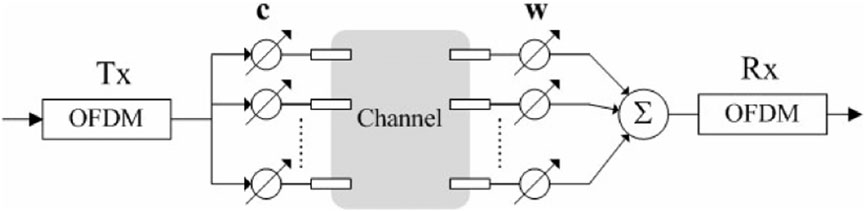
FIGURE 11. Hybrid beamforming methodology.
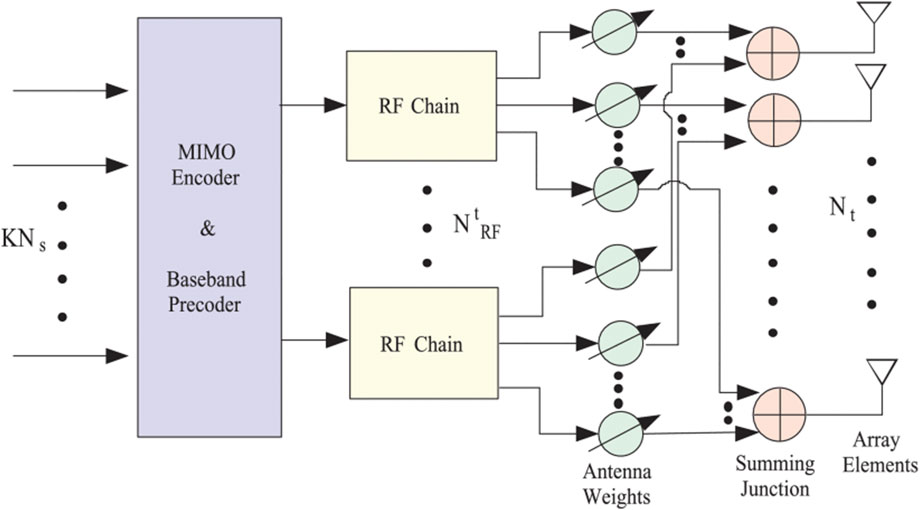
FIGURE 12. Extended hybrid beamforming transmitter.
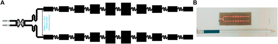
FIGURE 13. Hybrid beamforming MPA.
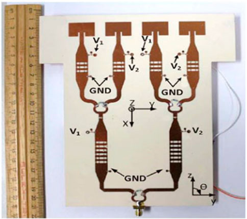
FIGURE 14. Defected microstrip structure design.

FIGURE 15. Yagi-Uda antenna. (A) Fabricated design. (B) Connected with VNA.
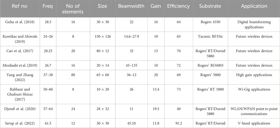
TABLE 2. Comparison of beamforming analog antenna arrays and digital arrays.
TABLE 3. Comparison of techniques used for microstrip patch antenna array.
Beam steering microstrip antennas for 5G communication systems offer several advantages, such as high gain, compact size, and cost-effectiveness. However, they also face certain challenges and limitations that must be addressed. Here are some of the challenges and limitations associated with beam steering microstrip antennas for 5G. Microstrip antennas typically have a limited steering range due to their inherent narrow bandwidth and small size. This limits their ability to steer the beam over a wide angular range, especially for high-frequency applications in millimeter-wave bands (Sim et al., 2023). It may require complex designs or multiple antenna elements to achieve wider beam steering ranges. Similarly, Microstrip antennas often require a complex feed network to achieve beam steering. The design of the feed network becomes challenging as the number of elements in the array increases. Achieving precise phase and amplitude control across all elements requires careful impedance matching, signal routing, and power distribution, which can increase the complexity and cost of the antenna system which effects the overall size of the microstrip patch design. The manufacturing tolerances associated with microstrip antennas can impact their beam steering capabilities. Variations in the dimensions, substrate properties, and fabrication processes can lead to deviations from the desired antenna performance. Tight control over manufacturing processes and thorough testing and calibration procedures are necessary to achieve accurate beam steering. Based on the requirements of the future communication system, different methods have been described in this paper that can be employed for beamforming. Improving the bandwidth, increasing the scanning range, and reducing the fabrication cost are in addition to several challenges that need to be addressed in future activities. To provide higher system capacity or diversity, current and future wireless communication systems must support dual polarization. Previously, some techniques were utilized that typically required the duplication of hardware to achieve dual polarization or a double-sized beamforming network. Another interesting direction of research is the development of hybrid antenna arrays employing a combination of circuit-type BFNs and digital array processing techniques.
6 Conclusion
As the demand for high data rates is dramatically increasing, 5G and B5G are proposed to be the most cost-efficient networks. A microstrip patch antenna is believed to be the vital element to enable steering for the precise targeting of signals towards specific users and areas for the compact nature of today’s communication devices. By directing the antenna beams in the desired direction, coverage can be extended to areas that would otherwise be challenging to reach. This enables better signal reception, even at longer distances, and improves the overall coverage and range of the 5G network. The findings provide insights into optimizing the performance of 5G networks. The directional and steerable radiation patterns of microstrip patch antennas align effortlessly with the demands for increased data rates, reduced latency, and efficient spectrum utilization in 5G, addressing current challenges and enhancing overall network capabilities. As 6G technologies approach the horizon, this study positions microstrip patch antennas as crucial components for the anticipated requirements. Their adaptability, highlighted through our analysis, indicates their potential role in shaping the foundational architecture of 6G networks, setting the stage for advanced communication systems. This paper carried out a comprehensive overview of the beam-forming antenna array. Previously explored methodologies and techniques were discussed and with particular focus on analogue, digital a hybrid beamforming.
Author contributions
MS: Writing–original draft. AN: Writing–review and editing.
Funding
The author(s) declare financial support was received for the research, authorship, and/or publication of this article. This work was completed under the supervision of AN during the Ph.D. project at the University of Greenwich.
Conflict of interest
The authors declare that the research was conducted in the absence of any commercial or financial relationships that could be construed as a potential conflict of interest.
Publisher’s note
All claims expressed in this article are solely those of the authors and do not necessarily represent those of their affiliated organizations, or those of the publisher, the editors and the reviewers. Any product that may be evaluated in this article, or claim that may be made by its manufacturer, is not guaranteed or endorsed by the publisher.
References
Afzal, M. U., Esselle, K. P., Koli, N. Y., and Thalakotuna, D. N. (2021). “Wideband radial-line slot array antenna technology for near-field meta-steering systems,” in 2021 IEEE International Symposium on Antennas and Propagation and USNC-URSI Radio Science Meeting (APS/URSI), Singapore, Singapore, 04-10 December 2021 (IEEE), 575–576. doi:10.1109/APS/URSI47566.2021.9703749
Ahmed, I., Khammari, H., Shahid, A., Musa, A., Kim, K. S., Poorter, E. D., et al. (2018). A survey on hybrid beamforming techniques in 5G: architecture and system model perspectives. IEEE Commun. Surv. Tutorials 20, 3060–3097. doi:10.1109/comst.2018.2843719
Ali, E., Ismail, M., Nordin, R., and Abdulah, N. F. (2017). Beamforming techniques for massive MIMO systems in 5G: overview, classification, and trends for future research. Front. Inf. Technol. Electron. Eng. 18, 753–772. doi:10.1631/fitee.1601817
Aluigi, L., Orecchini, G., and Larcher, L. (2018). “A 28 GHz scalable beamforming system for 5G automotive connectivity: an integrated patch antenna and power amplifier solution,” in 2018 IEEE MTT-S International Microwave Workshop Series on 5G Hardware and System Technologies, Dublin, Ireland, 30-31 August 2018 (IMWS-5G), 1–3. doi:10.1109/IMWS-5G.2018.8484325
Ashok, K., and Sudha, T. (2019). “A review on beamforming techniques for full duplex MIMO relaying networks,” in 2019 2nd International Conference on Intelligent Computing, Kannur, India, 05-06 July 2019 (Instrumentation and Control Technologies (ICICICT), 111–118. doi:10.1109/ICICICT46008.2019.8993324
Burasa, P., Djerafi, T., and Wu, K. (2020). A 28 GHz and 60 GHz dual-band on-chip antenna for 5G-compatible IoT-served sensors in standard CMOS process. IEEE Trans. Antennas Propag. 69 (5), 2940–2945.
Butler, J., and Lowe, R. (1961). Beam-forming matrix simplifies design of electronically scanned antennas. Electron. Des. 9 (8), 170–173.
Cao, Y., Ayed, A. B., Xia, J., and Boumaiza, S. (2021). Uniformly distributed near-field probing array for enhancing the performance of 5G millimeter-wave beamforming transmitters. IEEE Microw. Wirel. Components Lett. 31 (6), 823–826. doi:10.1109/LMWC.2021.3067168
Cao, Y., Chin, K. S., Che, W., Yeng, W., and Lee, E. S. (2017). A compact 38 GHz multi-beam antenna array with multi-folded Butler matrix for 5G applications. IEEE Antennas Wirel. Propag. Lett. 16, 2996–2999. doi:10.1109/lawp.2017.2757045
Cao, Z., Qian, M., Adrianus, B. S., Yuqing, J., Wale, M. J., Chin, W. O., et al. (2016). Advanced integration techniques on broadband millimeter-wave beam steering for 5G wireless networks and beyond. IEEE J. Quantum Electron. 52 (1), 1–20. Art no. 0600620. doi:10.1109/JQE.2015.2509256
Cheng, Y. F., Ding, X., Shao, W., and Wang, B. Z. (2017). Planar wide-angle scanning phased array with pattern-reconfigurable windmill-shaped loop elements. IEEE Trans. Antennas Propag. 65 (2), 932–936. doi:10.1109/tap.2016.2632736
Ding, C., Guo, Y., Qin, P., Bird, T., and Yang, Y. (2014). A defected microstrip structure (DMS)-based phase shifter and its application to beamforming antennas. IEEE Trans. Antenna Propag. 62, 641–651. doi:10.1109/tap.2013.2290802
Djerafi, T., Fonseca, N. J. G., and Wu, K. (2010). “Design and implementation of a planar 4 × 4 Butler matrix in SIW technology for wideband applications,” in Proceedings of the 40th European Microwave Conference, Paris, France, 28-30 September 2010.910193.
Djerafi, T., and Wu, K. (2012). A low-cost wideband 77-GHz planar Butler matrix in SIW technology. IEEE Trans. Antennas Propag. 60 (10), 4949–4954. doi:10.1109/tap.2012.2207309
Elfatimi, A., Bri, S., and Saadi, A. (2018). “Comparison between techniques feeding for simple rectangular, circular and triangular patch antenna at 2.45 GHz,” in 2018 4th International Conference on Optimization and Applications (ICOA), Mohammedia, Morocco, 26-27 April 2018, 1–5. doi:10.1109/ICOA.2018.8370552
Eshaghi, M., and Rashidzadeh, R. (2022). “A 5.8 GHz array antenna based on 4x4 butler matrix for beamforming in 5G network,” in 2022 IEEE Sensors, Dallas, TX, USA, 30 October 2022 - 02 November 2022 (IEEE), 1–4. doi:10.1109/SENSORS52175.2022.9967033
Guha, H., Mukherjee, A., and Vasanthi, M. S. (2018). Hybrid beamforming based mmWave for future generation communication. Int. Res. J. Eng. Technol. 5 (2018), 1045–1050.
Guo, Y. J., and Ziolkowsk, R. W. (2021). Advanced antenna array engineering for 6G and beyond wireless communications. Wiley.
Huitema, L., and Monediere, T. (2012). Dielectric materials for compact dielectric resonator antenna applications. Dielectr. Mater. InTech. doi:10.5772/50612
Issa, K., Fathallah, H., Ashraf, M. A., Vettikalladi, H., and Alshebeili, S. (2019). Broadband high-gain antenna for millimetre-wave 60-GHz band. Electronics 8, 1246. doi:10.3390/electronics8111246
Jebabli, E., Hayouni, M., and Choubani, F. (2022). “A low profile beamforming microstrip antenna array for 5G applications using butler matrix,” in 2022 International Wireless Communications and Mobile Computing (IWCMC), Dubrovnik, Croatia, 116–120. doi:10.1109/IWCMC55113.2022.9824417
Jiang, Z. H., Zhang, L., Zhang, Y., Yu, C., Cai, L., Zheng, S., et al. (2018). A compact triple-band antenna with a notched ultra-wideband and its MIMO array. IEEE Trans. Antennas Propag. 66 (12), 7021–7031.
Kawitkar, R. S., and Ahiwale, H. S. (2019). Design and analysis of compact hybrid equal and unequal power divider with wide isolation. Int. Res. J. Eng. Technol. 6, 531–533.
Kim, J. W., Youn, J. H., Rho, S. H., Lee, J. E., Jeon, Y. B., Ok, J. W., et al. (2018). Practical method to extract azimuth angle of target for air-borne antenna hybrid mono-pulse radar system. J. Korean. Inst. Elect. Eng. Sci. 29 (9), 735–738.
Klemes, M., Boutayeb, H., and Hyjazie, F. (2016). “Orbital angular momentum (OAM) modes for 2-D beam-steering of circular arrays,” in 2016 IEEE Canadian Conference on Electrical and Computer Engineering (CCECE), Vancouver, BC, Canada, 1–5. doi:10.1109/CCECE.2016.7726746
Li, A., and Luk, K.-M. (2020). Single-layer wideband end-fire dual-polarized antenna array for device-to-device communication in 5G wireless systems. IEEE Trans. Veh. Technol. 69 (5), 5142–5150. doi:10.1109/tvt.2020.2979636
Li, Y., Jiang, Z. W., Xiao, S. Y., Huang, C. Z., and Li, Y. F. (2018). Terbium(III) organic gels: Novel antenna effect-induced enhanced electrochemiluminescence emitters. Anal. Chem. 90 (20), 12191–12197. doi:10.1021/acs.analchem.8b03383
Lian, J.-W., Ban, Y.-L., Yang, Q.-L., Fu, B., Yu, Z.-F., and Sun, L.-K. (2018). Planar millimeter-wave 2-D beam-scanning multibeam array antenna fed by compact SIW beam-forming network. IEEE Trans. Antennas Propag. 66 (3), 1299–1310. doi:10.1109/tap.2018.2797873
Liao, S.-H., Chen, C.-H., Chiu, C.-C., and Ho, M.-H. (2015). “Comparison of different antenna arrays for the channel capacity,” in 2015 International Conference on Computing, Communication and Security (ICCCS), Pointe aux Piments, Mauritius, 04-05 December 2015, 1–5. doi:10.1109/CCCS.2015.7374139
Liu, A., Sheng, W., and Riihonen, T. (2022). Per-antenna self-interference cancellation beamforming design for digital phased array. IEEE Signal Process. Lett. 29, 2442–2446. doi:10.1109/LSP.2022.3224829
Manzillo, F. F., Nastri, R., Spella, M., Gentile, G., and Spirito, M. (2013). A 60-GHz passive broadband multibeam antenna system in fused silica technology. IEEE Antennas Wirel. Propag. Lett. 12, 1376–1379. doi:10.1109/LAWP.2013.2286207
Moubadir, M., Mchbal, A., Touhami, N. A., and Aghoutane, M. (2019). A switched beamforming network for 5G modern wireless communications applications. Procedia Manuf. 32, 753–761. doi:10.1016/j.promfg.2019.02.282
Muñoz, R., Simon, R., Paul, V. D., Juan, B., Evangelos, G., Manso, C., et al. (2021). Experimental demonstration of dynamic optical beamforming for beyond 5G spatially multiplexed fronthaul networks. IEEE J. Sel. Top. Quantum Electron. 27 (6), 1–16. Art no. 8600216. doi:10.1109/JSTQE.2021.3079726
Nwalozie, G., Okorogu, V., Maduadichie, S., and Adenola, A. (2013). A simple comparative evaluation of adaptive beam forming algorithms. Int. J. Eng. Innovative Technol. 2, 417–424.
Patil, R., and Popalghat, S. (2016). A review of various types of patch antenna. Int. J. Recent Innovation Trends Comput. Commun. 4, 653–655.
Patterson, C. E., Khan, W. T., Ponchak, G. E., May, G. S., and Papapolymerou, J. (2012). A 60-GHz active receiving switched-beam antenna array with integrated Butler matrix and GaAs amplifiers. IEEE Trans. Microw. Theory Techn. 60 (11), 3599–3607. doi:10.1109/tmtt.2012.2213834
Rabbani, M. S., and Ghafouri-Shiraz, H. (2017). Liquid crystalline polymer substrate-based THz microstrip antenna arrays for medical applications. IEEE Antennas Wirel. Propag. Lett. 16, 1533–1536. doi:10.1109/LAWP.2017.2647825
Rahayu, Y., Kurniawan, R., and Sari, I. P. (2019). New design of 60 GHz MIMO 2 × 4 patch rectangular antenna array for wireless gigabit (Wi-Gig) application. Int. J. Electr. Energy Power Syst. Eng. 2, 7–10.
Rao, L., Pant, M., Malviya, L., Parmar, A., and Charhate, S. V. (2021). 5G beamforming techniques for the coverage of intended directions in modern wireless communication: in-depth review. Int. J. Microw. Wirel. Technol. 13 (10), 1039–1062. doi:10.1017/s1759078720001622
Rivas, M., Xie, S., and Su, D. (2010). “A review of adaptive beamforming techniques for wideband smart antennas,” in 2010 6th International Conference on Wireless Communications Networking and Mobile Computing (WiCOM), Chengdu, China, 23-25 September 2010 (IEEE), 1–5. doi:10.1109/WICOM.2010.5600119
Saeed, M. A., Ahmad, U., Ullah, M. F., Siddique, M., Ali, U., and Qammar, M. S. (2021). “Rectangular loop mm-wave antenna for wearable applications,” in 2021 International Conference on Electrical, Communication, and Computer Engineering (ICECCE), Kuala Lumpur, Malaysia, 12-13 June 2021 (IEEE), 1–4. doi:10.1109/ICECCE52056.2021.9514220
Saeed, M. A., and Nwajana, A. (2022). “A novel beamforming antenna array for 5G and beyond applications,” in 2022 International Conference on Engineering and Emerging Technologies (ICEET), Kuala Lumpur, Malaysia, 27-28 October 2022 (IEEE), 1–4. doi:10.1109/ICEET56468.2022.10007412
Serup, D. E., Pedersen, G. F., and Zhang, S. (2022). Combined single-layer K-band transmitarray and beamforming S-band antenna array for satcom. IEEE Open J. Antennas Propag. 3, 1134–1140. doi:10.1109/OJAP.2022.3203253
Shelton, J. (1969). Reduced sidelobes for Butler-matrix-fed linear arrays. IEEE Trans. Antennas Propag. AP-17 (5), 645–647. doi:10.1109/tap.1969.1139525
Sim, C.-Y.-D., Lo, J.-J., and Chen, Z. N. (2023). Design of a broadband millimeter-wave array antenna for 5G applications. IEEE Antennas Wirel. Propag. Lett. 22 (5), 1030–1034. doi:10.1109/LAWP.2022.3231358
Tariq, S., Psychoudakis, D., Eliezer, O., and Khan, F. (2018). “A new approach to antenna beamforming for millimeter-wave fifth generation (5G) systems,” in 2018 Texas Symposium on Wireless and Microwave Circuits and Systems (WMCS), Waco, TX, USA, 05-06 April 2018 (IEEE), 1–5.
Tekkouk, K., Hirokawa, J., Sauleau, R., Ettorre, M., Sano, M., and Ando, M. (2015). Dual-layer ridged waveguide slot array fed by a Butler matrix with sidelobe control in the 60-GHz band. IEEE Trans. Antennas Propag. 63 (9), 3857–3867. doi:10.1109/tap.2015.2442612
Varum, T., Ramos, A., and Matos, J. N. (2018). “Planar microstrip series-fed array for 5G applications with beamforming capabilities,” in 2018 IEEE MTT-S International Microwave Workshop Series on 5G Hardware and System Technologies (IMWS-5G), Dublin, Ireland, 30-31 August 2018 (IEEE), 1–3. doi:10.1109/IMWS-5G.2018.8484697
Wang, J., Qu, S., Li, L., Wang, J., Feng, M., Ma, H., et al. (2017). All-dielectric metamaterial frequency selective surface. J. Adv. Dielectr. 7 (5), 1730002. doi:10.1142/s2010135x1730002x
Wang, X., et al. (2018). “28 GHz multi-beam antenna array based on A compact wideband 8×8 butler matrix,” in 2018 IEEE International Symposium on Antennas and Propagation & USNC/URSI National Radio Science Meeting, Boston, MA, USA, 08-13 July 2018 (IEEE), 2177–2178. doi:10.1109/APUSNCURSINRSM.2018.8609450
Wang, Y., Zhu, D., Jin, G., Yu, Q., Wang, P., Niu, S., et al. (2022). A robust digital beamforming on receive in elevation for airborne MIMO SAR system. IEEE Trans. Geoscience Remote Sens. 60, 1–19. Art no. 5233619. doi:10.1109/TGRS.2022.3199424
Wu, M., Zhang, B., Zhou, Y., and Huang, K. (2022). A double-fold 7×8 butler matrix-fed multibeam antenna with a boresight beam for 5G applications. IEEE Antennas Wirel. Propag. Lett. 21 (3), 516–520. doi:10.1109/lawp.2021.3136913
Wu, Z., Li, L., Li, Y., and Chen, X. (2015). Metasurface superstrate antenna with wideband circular polarization for satellite communication application. IEEE Antennas Wirel. Propag. Lett. 15, 374–377.
Yang, G., Li, J., Zhou, S. G., and Qi, Y. (2017). A wide-angle E-plane scanning linear array antenna with wide beam elements. IEEE Antennas Wirel. Propag. Lett. 16, 2923–2926. doi:10.1109/lawp.2017.2752713
Yang, G., and Zhang, S. (2022). Dual-Band shared-aperture multiple antenna system with beam steering for 5G applications. IEEE Trans. Circuits Syst. II Express Briefs 69 (12), 4804–4808. doi:10.1109/TCSII.2022.3201009
Keywords: microstrip patch antenna, rectangular patch, 5G, millimetre wave, linear array, microstrip line
Citation: Saeed MA and Nwajana AO (2024) A review of beamforming microstrip patch antenna array for future 5G/6G networks. Front. Mech. Eng 9:1288171. doi: 10.3389/fmech.2023.1288171
Received: 03 September 2023; Accepted: 21 December 2023;
Published: 21 February 2024.
Edited by:
Patrick Uche Okafor, Enugu State University of Science and Technology, NigeriaReviewed by:
Dorathy Abonyi, Enugu State University of Science and Technology, NigeriaMuneeb Ahmad, Kumoh National Institute of Technology, Republic of Korea
Anthony Nnaji, Enugu State University of Science and Technology, Nigeria
Copyright © 2024 Saeed and Nwajana. This is an open-access article distributed under the terms of the Creative Commons Attribution License (CC BY). The use, distribution or reproduction in other forums is permitted, provided the original author(s) and the copyright owner(s) are credited and that the original publication in this journal is cited, in accordance with accepted academic practice. No use, distribution or reproduction is permitted which does not comply with these terms.
*Correspondence: Muhammad Asfar Saeed, M.A.Saeed@greenwich.ac.uk