Numerical study on the optimized thickness of layer configuration against the 7.62 APM2 projectile
 Divyanshu S. Morghode1
  Sachin Salunkhe
 Lenka Cepova
 Emad Abouel Nasr
- 1Department of Mechanical Engineering, Defense Institute of Advanced Technology, Pune, India
- 2Department of Biosciences, Saveetha School of Engineering, Saveetha Institute of Medical and Technical Sciences, Chennai, India
- 3Department of Mechanical Engineering, Gazi University Faculty of Engineering, Ankara, Türkiye
- 4Department of Machining, Assembly and Engineering Metrology, Faculty of Mechanical Engineering, VSB—Technical University of Ostrava, Ostrava, Czechia
- 5Department of Industrial Engineering, College of Engineering, King Saud University, Riyadh, Saudi Arabia
This study aimed to select suitable materials and optimize the thickness of these materials so that they could prevent the perforation of 7.62-mm AP bullets at 830 m/s impact velocity. A numerical method is used to analyze the impact on layered configurations of Al2O3 and Al 7075-T651 to fulfill this aim. In order to optimize the thickness of the armor, normal impact and angular impact conditions were considered. Initially, a 20-mm Al2O3 front plate with a 20-mm Al 7075-T651 back plate is analyzed for layered configuration. Back plate thickness is reduced in steps to 10 mm such that no plastic deformation is observed on the rear side of the target. For further optimization of weight, the thickness of the Al2O3 plate is reduced to 18 mm. The weight of this configuration is 1.77 kg, and the areal density is 97.22 kg/m2. This configuration is analyzed for target orientations such as 80°, 70°, and 60°. In this analysis, the projectile deformed in a mushroom shape for 90° and 80° target orientations, while for 70° and 60° target orientations, the projectile experienced more damage on the shank part. The most effective configuration with the highest degree of ballistic performance is a layered combination of the 18-mm Al2O3 front plate and 10-mm Al 7075-T651 back plate at 70° target orientation.
1 Introduction
Security forces must operate in highly dangerous areas where terrorist attacks are always unavoidable. Ideally, security forces must have only bulletproof vehicles in such high-risk areas to provide necessary protection from such attacks. However, due to a lack of resources, it is not possible to have bulletproof vehicles in such large numbers. Hence, non-bulletproof vehicles are used for the routine movement of troops. However, such vehicles are vulnerable to attacks and cannot provide the required protection to the troops. So, the only solution available is to convert a non-bulletproof vehicle into a bulletproof vehicle using add-on armor. However, add-on armor increases the weight of the vehicle. Hence, materials used for the add-on armor need to be carefully selected, considering their density and optimizing their thickness to minimize the effect of their weight on the vehicle. So, the question that needs to be answered is “which materials and of what thickness, when fixed on ordinary vehicles, will provide protection against 7.62-mm APM2 bullets and make the vehicle bulletproof?”.
Previous studies reveal that under the effect of high-velocity impact, materials show non-linear and dynamic behavior, including thermal softening, fracture, and strain rate hardening for metal (Forrestal et al., 1992; Forrestal and Warren, 2008; 2009; Børvik et al., 2009; 2010; Pedersen et al., 2011; Holmen et al., 2017), concrete (Rajput et al., 2017; 2018; Rajput and Iqbal, 2017), and ceramic (Den, 1991; Fellows and Barton, 1999) targets. The finite element analysis of bullets’ impact on various types of armor is done using explicit dynamic FE analysis. During such an analysis, different contact algorithms and material models are used. Flores-Johnson et al. (2011) performed numerical impact simulations on single-layer and multilayer configurations of steel and aluminum using a 7.62-mm AP bullet with an impact velocity of 770–950 m/s. LS-DYNA software was used. The results show that multi-layered plates with different materials show greater resistance at the same area density. Rahman et al. (2016) conducted similar simulations using high-strength steel and Al 7075-T6 as targets, in which they studied the ballistic limit, the process of penetration, and deformation. The results showed that the triple-layered configuration achieves maximum weight reduction without compromising performance.
Ceramic materials are widely used as armor materials because of their excellent ballistic resistance properties. Den (1991) studied that the projectile’s behavior during impact, identifying three phases: erosion of mass, mushrooming, and rigidity. Fellows and Barton (1999) developed impact models for semi-finite ceramic targets. Anderson and Walker (2005) presented the dwell phenomenon model for projectile impact on ceramic targets. An appropriate material model for steel core bullets, Al 2024-T351, and Al2O3 was given by Turhan et al. (2008), in which the plastic kinematic hardening model was used for steel core projectiles and Al 2024-T351, and the Johnson–Holmquist model was used for Al2O3. López-Puente et al. (2005) presented the optimum thickness of the toughened epoxy resin adhesive layer for alumina–aluminum armors. Mazaheri et al. (2017) studied the effect on ballistic limit velocity and energy absorption after wrapping Al foil on the impact face of Al2O3 tiles. The study shows a 13% increase in ballistic limit velocity and an 11% increase in energy absorption with just a 2.4% increase in weight. Gálvez et al. (2005) Pranay and Panigrahi (2022a), Pranay and Panigrahi (2022b), and Pranay and Panigrahi (2022c) conducted a numerical study for the development of projectiles and attempted effective penetration of targets using ANSYS Explicit Dynamics/AUTODYN software. In Gálvez et al. (2005) , the effect of projectile tumbling has been studied for ceramic and aluminum armor. Wei and Zhang (2014) experimentally studied the projectile deformation modes for soft-core and hard-core projectiles impacting ceramic targets at different impact velocities.
In previous studies, different investigators have studied different parameters involved in the ballistic impact of the bullet on the target: residual velocity post-impact, the velocity of the ballistic limit, the pattern of perforation, mechanisms of fracture, etc. Furthermore, various materials that can be used as armor, along with different combinations and configurations of these materials, were highlighted in previous studies.
From the literature review, it was observed that very few studies have been conducted on the optimization of armor plate thickness for proposing thickness for armor fabrication against 7.62-mm APM2 projectiles. Most of the work on ballistic impact in the open literature deals with metallic and non-metallic target materials with relatively low thicknesses and projectiles moving with sub-ordnance velocities. The penetration of multi-layered armor plates is a complex problem. In order to design protective structures, thickness and layer configurations are factors that must be considered carefully to ensure no penetration. It must also be ensured that no debris is projected to the rear of the armor and that there is no panel deflection. Thus, a systematic study remains needed to optimize the strength-to-weight ratio of armor materials while protecting against 7.62-mm APM2 bullets.
The purpose of this study was to select suitable materials in the layered configuration with an optimized thickness of each layer such that they can be used as add-on armor on the body of a vehicle. The considered materials are Al2O3 and Al 7075-T651. Al2O3 material has characteristics of high strength and low density, while Al 7075-T651 has characteristics of high strength and high ductility. Therefore, Al2O3 is considered the front plate so that it can absorb the initial impact energy, undergo brittle fracture, and cause high projectile deformation. Al 7075-T651 is considered the back plate so that it can absorb the residual energy from the impact and fragments of Al2O3 created due to its fracture. Most of the layered configuration studies do not consist of specific thicknesses of add-on armor for protection against projectiles. So, in this study, the optimum thickness is considered based on two criteria: first, the armor must successfully stop the projectile, and second, there must be no plastic deformation on the rear surface of the armor.
This work presents a numerical study of the impact on the layered combination of Al2O3 and Al 7075-T651 by a 7.62-mm APM2 bullet fired at 830 m/s. Furthermore, to optimize the thickness of the armor, normal impact and angular impact conditions were considered. The following sections explain in detail the numerical approach followed by the results observed.
2 Research methodology
Initially, residual velocity is computed by numerical simulations while considering the normal impact at a given impact velocity on an Al 7075-T651 plate having a 20 mm thickness. The model is validated using the experiment results from the literature (Forrestal et al., 2010). A validated model is extended to study the layered armor consisting of Al 7075-T651 and Al2O3 at normal and oblique impact conditions. Figure 1 represents a detailed research methodology flow chart.
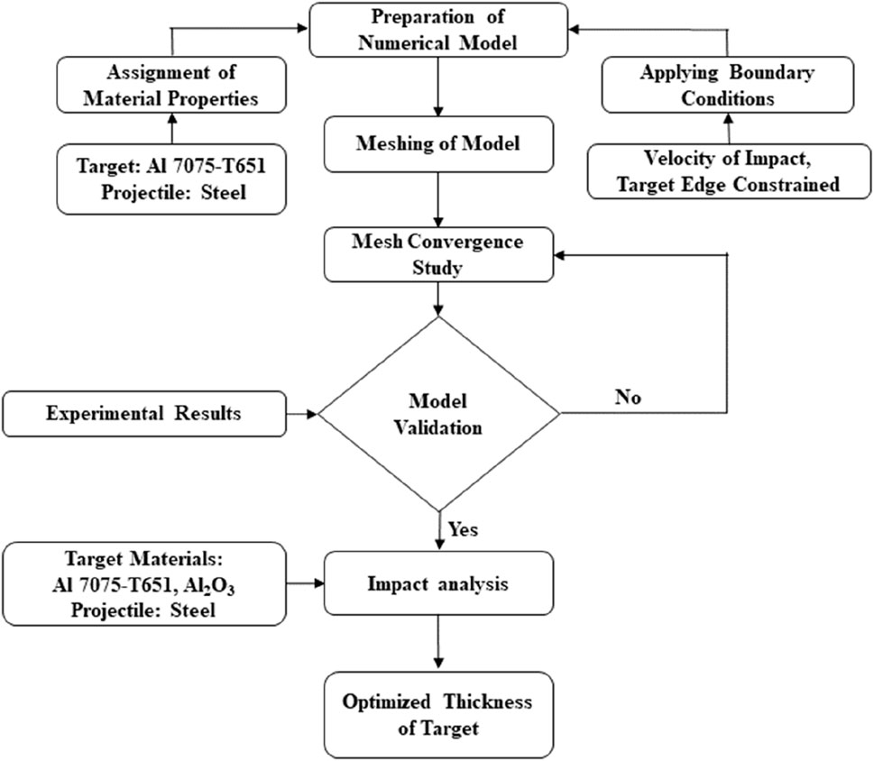
Figure 1. Research methodology flow chart.
2.1 Finite element modeling
2.1.1 Projectile
Most researchers working with standard NATO ammunition use 7.62-mm steel-core bullets to analyze various target material impacts (Flores-Johnson et al., 2011). These bullets consist of an inner steel core and a protective outer jacket. This jacket is generally made of brass and is used to engage with the barrel’s lands so that spin can be provided to the bullet during its travel inside the barrel. However, this brass jacket does not affect the collision between the target material and bullet (Chen et al., 2013). Therefore, the jacket is not considered during the simulations to reduce the time required for computation. Senthil and Iqbal (2021) also used only the steel core, as shown in Figure 2, and compared the results with experimental data obtained using a projectile. The results matched the experiment results (Senthil and Iqbal, 2021). SolidWorks was used to design the bullet, and the design was imported into LS-DYNA for simulations.
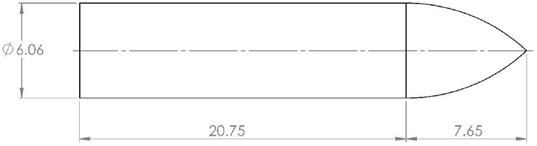
Figure 2. 7.62-mm AP projectile (all dimensions are in mm) (Senthil and Iqbal, 2021).
2.1.2 Target
LS-DYNA software was used for designing a model of the target. The target was designed as a circular plate with a diameter of 152 mm. This circular plate was further segregated into three regions. The impact region at the center of the circular target was designed as a square with each side measuring 10 mm. The second and third regions are circular and designed to have 30 mm and 50 mm diameters, respectively. Figure 3 shows the dimensions of the circular plate used as the target.
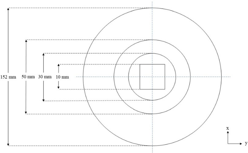
Figure 3. Target discretizations.
2.1.3 Meshing
It is well-known that the most accurate results are obtained when two conditions are satisfied: first, when the density of the mesh and number of elements are higher, and second, when elements are closest to the system’s boundary. To cover the maximum volume and curvature of the bullet and target plate, hexahedral solid elements with eight nodes, reduced integration, and the Hourglass effect’s stiffness control are used for meshing. The meshing of the bullet was done in ABAQUS, and the meshing of the target plate was done in LS DYNA. The duplicate nodes were either removed or merged, depending on their dimensions.
A comprehensive mesh convergence study was conducted to minimize the computation time and select the optimized element size for the projectile and impact region of the target. The results obtained by changing the element size were compared with results given in the literature (Forrestal et al., 2010). It was concluded that the size of elements in the square region at the center of the target plate would be 0.25 mm. Similarly, the size of the elements in the circular portion, having diameters of 30 and 50 mm, will be 0.5 and 1 mm, respectively. The size of an element beyond 50 mm in diameter will be 2 mm. Figure 4 represents the final mesh of the bullet and target plate.
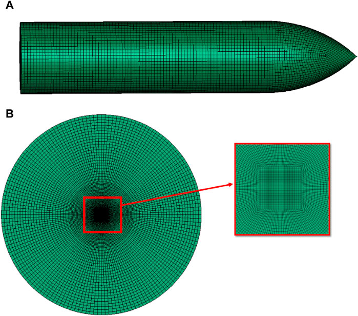
Figure 4. Mesh (A) projectile and (B) target.
2.2 Constitutive material models
2.2.1 Strength model by Johnson–Cook
The strength model given by Johnson and Cook (1983) and Johnson and Cook (1985) defines the behavior of the strength of materials subjected to impact with high velocities. The model gives yield stress, i.e., Y, as a function of strain hardening, strain rate hardening, and temperature softening, and the equation for the same is shown below.
where ɛp is the effective plastic strain, ɛp* is the normalized effective plastic strain rate, and TH is the homologous temperature [TH= (T–Troom)/(Tmelt–Troom)].
A, B, C, n, and m are material constants. The first bracket in Eq. 1 gives stress as the function of strain, which is determined by quasi-static tensile testing (ε∗p = 1.0 sec−1 and TH = 0). A is the yield stress at lower values of strains; B and n define strain hardening. The other two brackets represent the effects of hardening due to the strain rate and softening due to temperature. With softening due to thermal effects, yield strength is reduced to zero at melting temperatures Tmelt. The constants of materials are determined using the dynamic tensile test using a split Hopkinson Bar over a wide range of strain rates and temperatures.
2.2.2 Johnson–Cook failure model
The failure model given by Johnson–Cook was used to model material failures. Similarly, in the previous model, fracture strain, a material property, is given as an explicit function of temperature, strain rate, and pressure. The equation for the same is given as Eq. 2.
The dimensionless ratio of pressure and stress is represented as σ* = σm/σ¯, where σm is primary stress, (σ1 + σ2 + σ3)/3, and σ¯ is effective stress or Von Mises stress (3J2), where J2 is the second invariant of the stress deviator. Dimensionless strain rate ε∗ is ε/ε0, where ε0 is the unit strain rate. TH is the homologous temperature, produced by internal heating. D1, D2, D3, D4, and D5 are parameters of the model of fracture, and these can be obtained from experiments done in the laboratory.
Changes occurring while loading are depicted in the Johnson–Cook model using the concept of linear summation. This model calculates changes in failure strain using the stress state, temperature, strain rate, and damage accumulated during loading. However, this model does not account for the degradation of the strength of the material or stiffness. When the critical value of damage is reached, the values of pressure and stress are abruptly reduced to zero. For this reason, it is said to be an instantaneous failure model. Damage is computed as the cumulative value, as given in Eq. 3, and failure is fixed at a critical value, which is generally taken as 1.
where ɛ is the equivalent plastic strain increment that occurs during tensile loading and ɛf is the equivalent strain to fracture corresponding to instantaneous conditions during the accumulation of the increment of strain.
2.2.3 Johnson–Holmquist model
The Johnson–Holmquist model (Johnson and Holmquist, 1994), having an equation of state, model of strength, and model of damage, was used to define the behavior of Al2O3. Polynomial equation-of-state (EOS) calculated the current value of pressure as a function of volumetric change, the model of strength gave equivalent strength for undamaged and damaged material, and the model of damage was used to show the transition of material from undamaged to damaged states.
Normalized equivalent stress is defined as follows:
where σi* is the normalized intact equivalent stress, σf* is the normalized fracture stress, and D is damage (0 ≤ D ≤ 1).
Normalized intact equivalent stress is shown in Eq. 5, and normalized fractured equivalent stress is shown in Eq. 6.
where A, B, C, M, and N are constants of material and normalized pressure. P* = P/PHEL, where P is the actual pressure and PHEL is the pressure at the Hugoniot elastic limit (HEL). The HEL is the net compressive stress corresponding to uniaxial strain (shock wave) exceeding the elastic limit of the material. Normalized maximum tensile hydrostatic pressure is represented as T* = T/PHEL, where T is the maximum tensile hydrostatic pressure that material can withstand, and the dimensionless strain rate is ε* = ε/ε0, where ε is the actual equivalent strain rate and ε0 is the reference strain rate considered to be 1 s-1.
Hydrostatic pressure before and after damage was expressed using Eqs 7, 8, respectively.
where K1, K2, and K3 are the pressure constants. The volumetric strain is μ = ρ/ρ0−1, where ρ is the current density and ρ0 is the initial density of the material. ΔP is the pressure increment due to the bulking of material due to the accumulation of damage.
The fracture model’s damage criterion is the same as that of the Johnson–Cook [27], [28] model.
where Δε is the increase in the equivalent plastic strain, and εpf is the plastic strain to the fracture.
Plastic strain to the fracture of the material is given as follows:
where D1 and D2 are damage constants. The damage parameter D is the same as is described in the Johnson–Cook model.
2.2.4 Material properties
The material selected for the projectile was steel, as only the inner core of the 7.62-mm AP bullet was designed, and its brass jacket was neglected. The materials selected for the target were Al 7075-T561 and Al2O3 for three reasons:
1. It was observed from the literature review that both of these materials have been used for designing the vehicle armor.
2. Al 7075-T651 is a ductile material, and Al2O3 is a brittle material. Therefore, when used in a layered configuration, these two materials provide a perfect destroyer–absorber combination.
3. The densities of these materials are low compared to steel.
Thus, these materials provide a lightweight option for protection against AP bullets. Johnson–Cook (JC) strength (Johnson and Cook, 1983; Johnson and Cook, 1985) and failure model are used to define the behavior of steel and Al 7075-T651. Similarly, Johnson–Holmquist’s model is used to define the behavior of Al2O3 under bullet impact conditions. Material properties used for the projectile and target are given in Tables 1, 2, respectively.
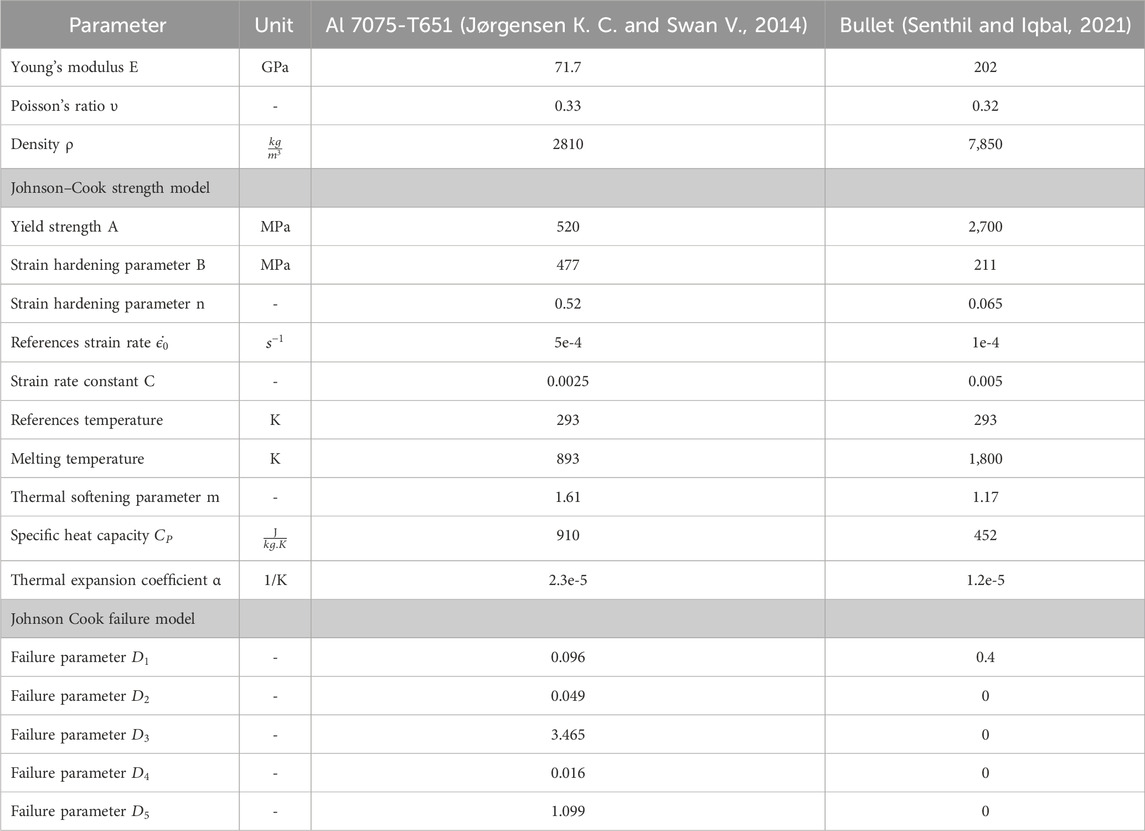
Table 1. Material property of Al 7075-T651 and bullet.
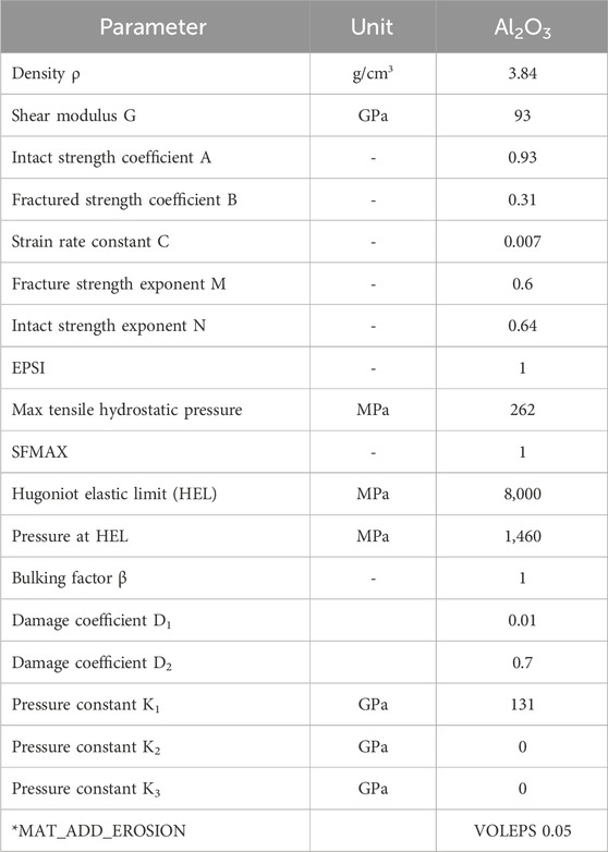
Table 2. Material properties for Al2O3 (Zochowski et al., 2021).
2.3 Model validation
The projectile and target models prepared for this study were required to be validated before further analysis was carried out. Therefore, experimental results from the literature (Forrestal et al., 2010) were used to validate the model prepared. As per the experimental result, when an AP bullet, having an impact velocity of 867.8 m/s, was fired on a 20-mm thick target plate of Al 7075-T651, the residual velocity obtained was 579.8 m/s. Hence, similar conditions were applied in the model prepared for the study, and the result observed after the simulation was compared with the result given in the literature (Forrestal et al., 2010).
LS-DYNA software was used in this work because it is one of the most acceptable software programs to conduct high-velocity impact simulations. Projectile impact velocity was taken as 867.8 m/s. Rotational and translational degrees of freedom along the boundary of the target were constrained so that there was no motion. Thus, the periphery of the target had fixed support. The friction coefficient was taken as 0.2. The time step was selected as 10e-5 s. Figure 5 depicts the assembly of different parts and boundary conditions.
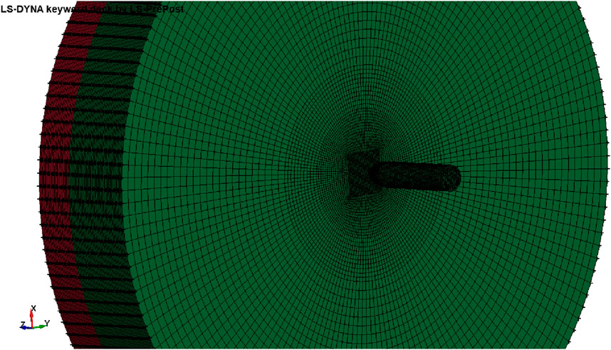
Figure 5. Assembly and boundary conditions of the model.
The adhesive bond between the Al2O3 plate and Al 7075-T651 plate was modeled by defining a contact model ‘tie-break surface to surface contact’ that will break when the stress limits are exceeded. Eroding surface contact was used to define interactions between the projectile and target plates. These contact algorithms work on the “penalty function” method. According to this method, contacting bodies are considered master and slave. The distance between the nodes of the slave body and the surface of the master body in the normal direction of a segment of the master body is checked. When penetration is detected, force is generated between the agent node and its point of contact with the surface of the master body to counteract the penetration. This force is dependent on the penetration value and the contacting body’s properties.
After applying initial and boundary conditions, the projectile’s residual velocity was computed by running LS DYNA simulations. The element size of the projectile was selected as 0.25 mm × 0.25 mm x 0.25 mm. Several elements in the target thickness direction were changed from 20 to 100, and residual velocities were calculated. The results obtained are tabulated in Table 3. The computation time also increased with the increasing number of elements in the thickness direction. When there were 50 elements in the thickness direction, the residual velocity obtained was 583 m/s.
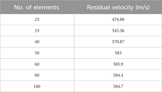
Table 3. Residual velocity with variation in the number of elements.
From the literature (Forrestal et al., 2010), the experimental residual velocity was 579.8 m/s. On comparing residual velocities observed from the experiment and simulation, it was observed that the error was approximately 0.7% and that the model was in the overestimation region. As the error was very low and in the overestimation region, it was safely assumed that the model was validated and that the model can be further extended to study layered configuration based on residual velocity, penetration depth, and weight parameters.
3 Numerical analysis
The validated model conditions were used for further analyses. The monolithic plates were initially considered with target materials: Al 7075-T651 and Al2O3. Most researchers use Al2O3 materials with layer configuration, i.e., Al2O3 material is used as an impact-absorbing material, and a ductile Al 7075-T651 back layer is used as a residual energy-absorbing material. In this study, monolithic, layered configurations and inclined target orientations are analyzed to optimize the weight of armor without affecting its functionality.
3.1 Monolithic plate analysis
3.1.1 Al 7075-T651
In order to know the penetration depth of the projectile inside the target, the thickness of the target was considered to be 50 mm, and impact simulations were conducted with an impact velocity of 830 m/s. The results showed that the projectile penetrated the target up to a depth of 38.7 mm, and no deformation was observed at the rear surface of the target. It was observed that only the projectile tip had been eroded. However, the target arrested the bullet, as shown in Figure 6. The areal density of the target is 140.5 kg/m2.
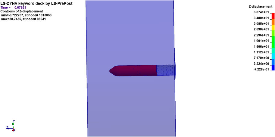
Figure 6. Depth of penetration for 50-mm Al 7075-T651 at an impact velocity of 830 m/s.
3.1.2 Al2O3
Furthermore, the bullet was impacted with the same velocity, i.e., 830 m/s on the 20-mm Al2O3 plate. The results showed that the Al2O3 plate was able to arrest the bullet. However, at the same time, it was observed that the Al2O3 plate had completely failed due to a brittle fracture. Impact simulations on the independent Al2O3 plate are shown in Figure 7.
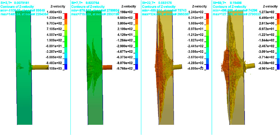
Figure 7. Impact simulations on an independent Al2O3 plate.
3.2 Layered configuration analysis
From the monolithic plate analysis, it is observed that in the case of the 50-mm-thick Al 7075-T651 target plate, the weight penalty was higher. However, in the case of 20-mm-thick Al 7075-T651, the bullet was perforating the target. Furthermore, in the case of 20-mm-thick Al2O3, even though the perforation is restricted, the target plate completely fails due to a brittle fracture. Therefore, Al2O3 and Al 7075-T651 plates were layered for better protection against a 7.62-mm steel core. The front plate was considered to be of Al2O3, and the back plate was considered to be of Al 7075-T651. Initially, each plate in a layered combination was considered 20-mm thick, and the impact simulation was conducted. It is observed that the Al2O3 plate itself successfully stopped the projectile, and only a few stresses were experienced by the Al 7075-T651 plate. The projectile had also experienced a large amount of deformation. Simulation images are given in Figure 8.
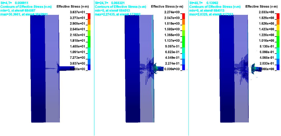
Figure 8. Impact on the layered configuration of the 20-mm-thick Al2O3 front plate and 20-mm-thick Al 7075-T651 back plate.
To further reduce the weight of the target, the thickness of the back plate was further reduced. It can be observed that Al2O3 has a higher density than Al 7075-T651. Thus, by reducing the thickness of Al2O3, the overall weight of the configuration will be reduced. However, protection against the projectile should not be compromised, as the projectile will shatter the Al2O3 plate, as discussed in the earlier section. Hence, to achieve optimum protection, only Al 7075-T651 plate thickness is reduced in steps such that no plastic deformation occurs at the rear side of the back plate.
The results showed that a minimum of a 10-mm Al 7075-T651 back plate is needed to stop the plastic deformation at the rear surface of the back plate. It was also observed that as the back plate thickness is reduced from 20 mm to 10 mm, Al2O3 plate damage increases, as shown in Figure 9. This was due to the increase in reflected stress wave intensity. The analyzed layered configurations have a 20-mm Al2O3 front plate and a 10-mm Al 7075-T651 back plate with an area density of 104.9 kg/m2.
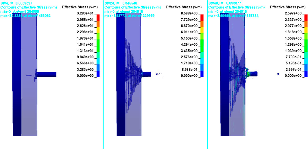
Figure 9. Impact on the 20-mm-thick Al2O3 front plate and 10-mm-thick Al 7075-T651 back plate.
For further reduction in weight, the Al2O3 plate thickness was reduced from 20 mm to 18 mm. The results showed that projectile penetration was restricted, but damage to the Al2O3 plate increased with the formation of cone fractures, as shown in Figure 10. The areal density of this configuration was found to be 97.22 kg/m2.
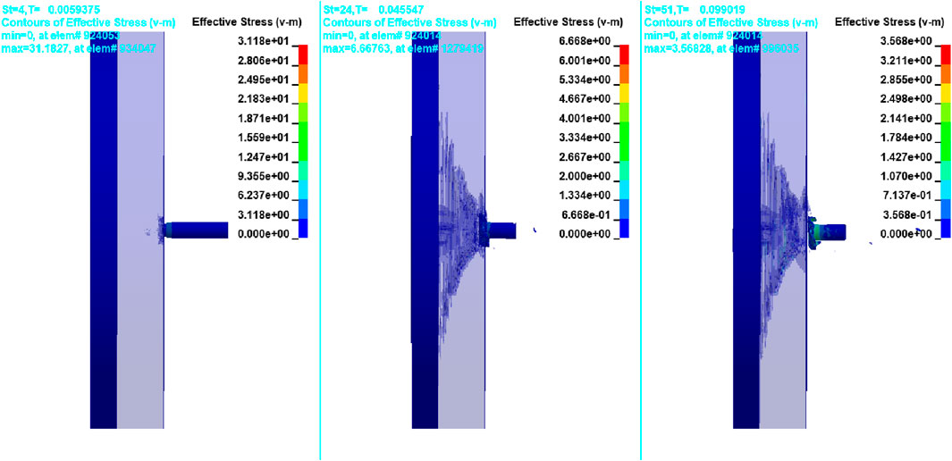
Figure 10. Impact on the 18-mm-thick Al2O3 front plate and 10-mm-thick Al 7075-T651 back plate.
3.3 Inclined orientation of layered configuration
As mentioned in the earlier section, in real-world scenarios, most of the armor is fixed in an inclined position to increase the target’s effective thickness and deviate the projectile from its normal penetration path or ricochet. As discussed in the previous section, the 18-mm Al2O3 front plate and 10-mm Al 7075-T651 back plate configurations were analyzed for different target orientations to check the effectiveness of the target. The target orientations considered were 80°, 70°, and 60°. The penetration simulations are shown in Figures 11–13.
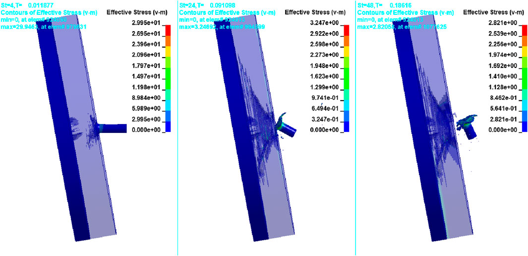
Figure 11. Impact on 80° target orientation.
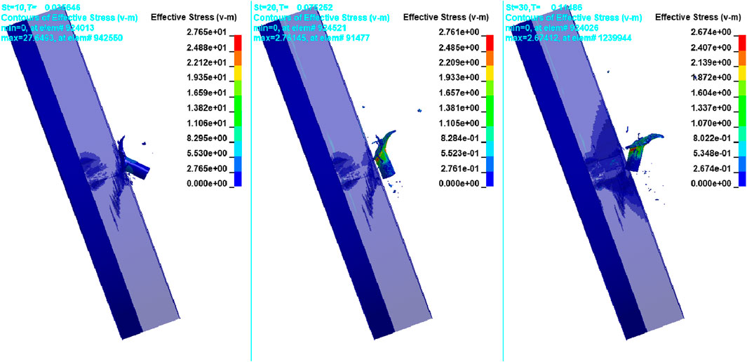
Figure 12. Impact on 70° target orientation.
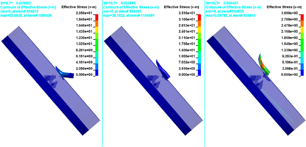
Figure 13. Impact on 60° target orientation.
4 Results and discussions
4.1 Monolithic plate analysis
The impact analysis was carried out on the Al 7075-T651 target plate with a 50 mm thickness, using a projectile with a velocity of impact of 830 m/s. The results showed that the projectile penetrated the target up to a depth of 38.7 mm. The failure mode of the Al 7075-T651 plate was ductile hole enlargement.
At 830 m/s and with a target thickness of 20 mm, a monolithic Al2O3 plate was analyzed. When the projectile impacted Al2O3, the primary resistance to penetration was due to the compressive strength of Al2O3. The projectile was deformed, fractured, and deflected, as its compressive strength was high. Since the projectile has a low aspect ratio, it was defeated as the strength of Al2O3 was greater than that of the projectile. At the same time, the stresses exerted by the projectile pulverized Al2O3 in the small region just ahead of the leading edge of the projectile. Specific fracture surface energy for Al2O3 was little in tension. However, the energy required to produce a small fracture surface area under huge dynamic shear and compressive forces was significantly large. Thus, the energy absorbed in creating the powdered surface area was significantly higher.
Another significant factor that offers resistance in Al2O3 penetration is the damage cone produced at the penetrator’s leading edge. Cone formation is characteristic of quasi-static indentation, which follows the path of maximum tensile stress inside the material. The cone was observed to become broad at the base, and the same is true because of stress wave interaction with reflections from the free surface. Cone formation spreads the load of the projectile over a large area of the target. Thus, the density of the projectile’s kinetic energy is reduced. Khan et al. (2020) studied the monolithic Al2O3 plate failure behavior. They measured the diameter of the fracture cone at the impact surface and rear surfaces of the target plate for different impact velocities. Experimental studies found that the ratio of the cone’s diameter at the impact surface to the cone’s diameter at the free surface was in the range of 2.8–4.73, while numerical simulation ratios were in the range of 2.8–4.53. In this research, the cone’s diameter at the free surface was approximately 54.41 mm, and at the impact, the diameter was 16.65 mm. The ratio of the cone’s diameter at the free surface to the impact surface is approximately 3.267, which is in the range of the study done by Khan et al. (2020), and the areal density was 76.8 kg/m2.
From the simulations, it was seen that the projectile got significantly deformed. The Al2O3 plate has formed radial cracks beyond the cone formations. Within the cone at the free surface, the complete material was shattered by forming fragments of high velocity, which can create damage behind the free surface of the Al2O3 target. Therefore, a more ductile and tough layer must be placed at the rear of Al2O3 to catch cones and fragments. Furthermore, monolithic targets need more thickness to arrest perforation and, thus, cause a significant increase in target weight. Hence, a layered combination of the Al2O3 front plate and Al 7075-T651 back plate was considered to optimize the strength-to-weight ratio and have optimum protection from the 7.62-mm AP bullet.
4.2 Layer configuration of Al 7075-T651 and Al2O3
The initial layered configuration was a 20-mm-thick Al2O3 front plate and a 20-mm-thick Al 7075-T651 back plate. The projectile tip was damaged during initial penetration, and the rear plate yielded at the Al2O3 interface. A crack was initiated at the rear face of Al2O3 and followed the motion of the rear plate. The same grows in magnitude in the impact direction. Subsequently, the fracture cone grew from the interface between the bullet and the target and grew in the direction of penetrator travel from 8 to 14 µ secs. The projectile eroded, and Al2O3 became rubble due to multiple cracks that coalesced and intersected. The projectile eroded due to plastic flow and yielding in the direction perpendicular to its travel. Erosion occurred because the stresses in the projectile were higher than its strength. Approximately 40% of the mass and energy of the projectile was carried away by the eroded material of the projectile. Beyond 14 µ secs, the erosion of the bullet ceased, and the rear plate absorbed the remainder of the energy in the system of the bullet target. The projectile can advance only if the target material is pushed ahead or to the sides. Due to rear confinement, crushed Al2O3 cannot be pushed ahead.
Ductility is one of the key properties needed in the back plate, as the ductility of the material will allow it to absorb the stress waves formed by impact in the Al2O3 material. As the ductile material absorbs stress waves, the intensity of reflecting stress waves in Al2O3 will decrease, causing less damage to Al2O3 and improving the armor’s effectiveness.
It was observed that the fragments had been successfully restricted, and there was no damage on the rear surface of the back plate. The Al 7075-T651 target also caused the Al2O3 target to experience less damage than the monolithic plate. The plate perforation was successfully restricted with a layered configuration.
4.3 Inclined orientation of a layered configuration
From the literature (Senthil and Iqbal, 2021), it was observed that the projectile will ricochet when it impacts stronger targets in inclined positions. Most studies on projectile behavior considered the projectile a rigid body. In this analysis, the bullet is considered to be deformable. The analysis found that the projectile head part was completely deformed at 90° and 80° target orientations, and a mushroom-type structure was formed. However, at 70° and 60°, the projectile gets ricocheted from the normal penetration path, as shown in Figures 12, 13. As the projectile path deviated, the projectile experienced more damage on the shank part, especially on the side sliding over the target. The deformation of the projectile is given in Figure 14. In Wei and Zhang (2014), it is also mentioned that as the impact velocity increases, the projectile deformation behavior changes from mushrooming to shearing cracking and fragmentation. In this analysis, the projectile deformation mode was mushrooming at normal impact conditions for the considered impact velocity.
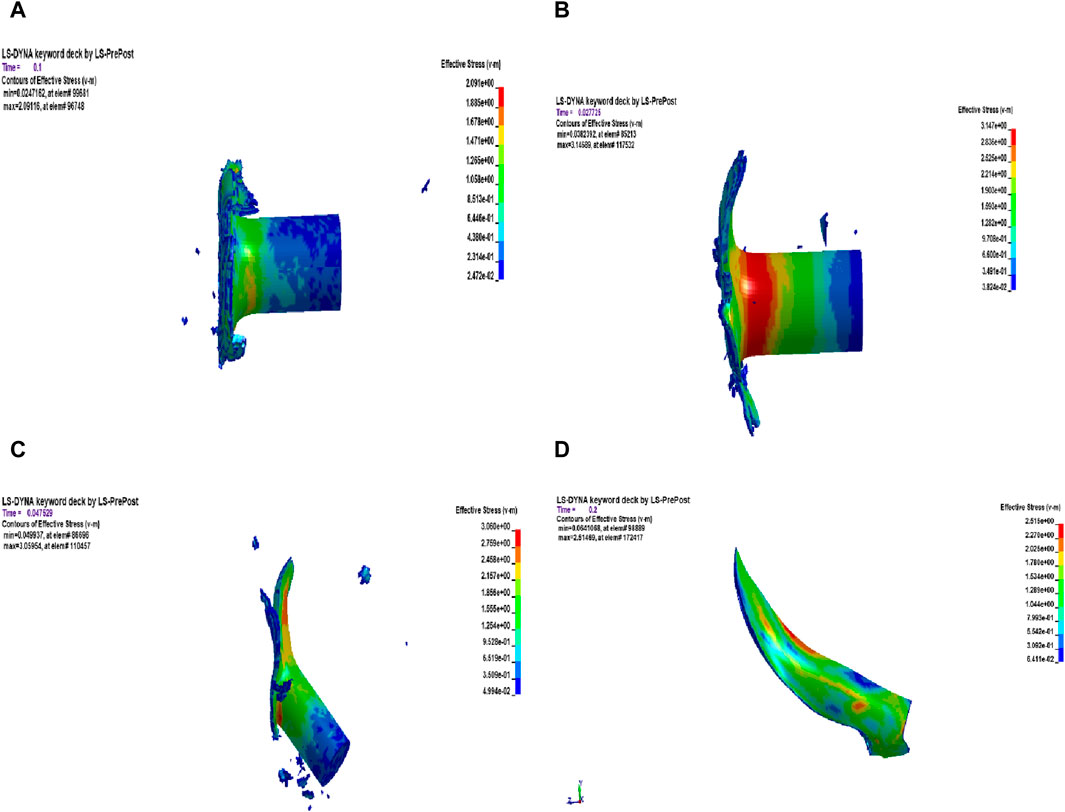
Figure 14. Projectile deformations for (A) 90°, (B) 80°, (C) 70°, and (D) 60° target orientations.
As the projectile was ricocheted, the velocity variation graphs were plotted from data obtained from LS-DYNA. As the target inclination increases, the projectile will start to slide in the direction of deviation, and the projectile will have a higher residual velocity than normal impact. The velocity–time graphs for the projectile are shown in Figure 15.
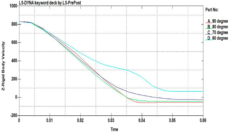
Figure 15. Velocity variation graphs for different target orientations (unit of velocity is m/s and time is 10–3 s).
From the simulations (Figures 10–13) and velocity variation graphs for the projectile (Figure 15), it was observed that as the target orientation varies from 90° to 60°, the projectile starts deviating from its normal penetration path. As the front plate is an Al2O3 plate of high toughness, both the projectile and Al2O3 plate will experience damage at the time of impact, and the projectile will slide over the surface of the damaged Al2O3 plate. In the simulations, gravitation effects were not considered. Hence, the projectile-traveling path was observed to be approximately parallel to the target surface. However, in real-world scenarios, because of the gravitational effect, the projectile might fall immediately or travel parallel to the target surface for some time before falling.
5 Conclusion
In this paper, a numerical study was conducted to analyze the ballistic performance of the layered configuration of Al2O3 and Al 7075-T651 when impacted by a 7.62-mm APM2 bullet. The ballistic performance was also evaluated for different target orientations, such as 80°, 70°, and 60° target inclinations. It is observed that the projectile will deviate from its normal penetration path at 70° and 60° target inclinations. Damage induced by bullets is increased with higher target inclinations. The residual velocities of bullets also increased with higher target inclinations. The effect of target inclinations becomes more prominent at a higher inclination angle.
From this study, the following conclusions are drawn:
• 20-mm-thick Al2O3 front plate with a 20-mm-thick Al 7075-T651 back plate successfully restricted the projectile. The area density is 133 kg/m2.
• Al 7075-T651 back plate thickness is reduced in steps to 10 mm. The real density for this combination is 104.9 kg/m2.
• For further optimization of weight, the thickness of the Al2O3 plate is reduced to 18 mm. If the thickness is further reduced, the Al2O3 plate will experience greater damage because of reflected stress waves from the back plate. The rear surface of Al 7075-T651 is also induced by higher stresses. The area density is 97.22 kg/m2.
• The projectile deformed in a mushroom shape for 90° and 80° target orientations, while for 70° and 60° target orientations, the projectile experienced more damage on the shank part.
• Based on data obtained from the study, the best-performing configuration is the layered combination of an 18-mm-thick Al2O3 front plate and a 10-mm Al 7075-T651 back plate at 70° target orientation. This combination successfully restricts the bullet, with less damage to the armor and more damage to the bullet. Furthermore, the bullet’s velocity is successfully reduced to zero without any residual velocity post-impact due to the sliding of the projectile on the armor surface.
Data availability statement
The datasets presented in this study can be found in online repositories. The names of the repository/repositories and accession number(s) can be found in the article/Supplementary Material.
Author contributions
DM: conceptualization, data curation, formal analysis, investigation, methodology, project administration, resources, writing–original draft, and writing–review and editing. DT: investigation, methodology, resources, software, supervision, validation, visualization, writing–original draft, and writing–review and editing. SS: methodology, project administration, resources, software, supervision, validation, and writing–review and editing. LC: funding acquisition, investigation, methodology, project administration, and writing–review and editing. EA: funding acquisition, investigation, methodology, project administration, and writing–review and editing.
Funding
The author(s) declare that financial support was received for the research, authorship, and/or publication of this article. The authors extend their appreciation to King Saud University for funding this work through Researchers Supporting Project number (RSP 2024R164), King Saud University, Riyadh, Saudi Arabia.
Conflict of interest
The authors declare that the research was conducted in the absence of any commercial or financial relationships that could be construed as a potential conflict of interest.
Publisher’s note
All claims expressed in this article are solely those of the authors and do not necessarily represent those of their affiliated organizations, or those of the publisher, the editors, and the reviewers. Any product that may be evaluated in this article, or claim that may be made by its manufacturer, is not guaranteed or endorsed by the publisher.
References
Anderson, C. E., and Walker, J. D. (2005). An analytical model for dwell and interface defeat. Int. J. Impact Eng. 31 (9), 1119–1132. doi:10.1016/j.ijimpeng.2004.07.013
Børvik, T., Dey, S., and Clausen, A. H. (2009). Perforation resistance of five different high-strength steel plates subjected to small-arms projectiles. Int. J. Impact Eng. 36 (7), 948–964. doi:10.1016/j.ijimpeng.2008.12.003
Børvik, T., Hopperstad, O. S., and Pedersen, K. O. (2010). Quasi-brittle fracture during structural impact of AA7075-T651 aluminium plates. Int. J. Impact Eng. 37 (5), 537–551. doi:10.1016/j.ijimpeng.2009.11.001
Chen, X. W., Gao, Y. B., and He, L. L. (2013). Analysis on perforation of ductile metallic plates by APM2 bullets. Key Eng. Mater. 535–536, 68–71. doi:10.1260/2041-4196.4.1.65
Den, R. P. C. (1991). Impact on ceramic faced armour. PhD Thesis. Netherlands: Delft Technical University.
Fellows, N. A., and Barton, P. C. (1999). Development of impact model for ceramic-faced semi-infinite armour. Int. J. Impact Eng. 22 (8), 793–811. doi:10.1016/s0734-743x(99)00017-2
Flores-Johnson, E. A., Saleh, M., and Edwards, L. (2011). Ballistic performance of multi-layered metallic plates impacted by a 7.62-mm APM2 projectile. Int. J. Impact Eng. 38 (12), 1022–1032. doi:10.1016/j.ijimpeng.2011.08.005
Forrestal, M. J., Børvik, T., and Warren, T. L. (2010). Perforation of 7075-t651 aluminum armor plates with 7.62 mm APM2 bullets. Exp. Mech. 50 (8), 1245–1251. doi:10.1007/s11340-009-9328-4
Forrestal, M. J., Luk, V. K., Rosenberg, Z., and Brar, N. (1992). Penetration of 7075-T651 aluminum targets with ogival-nose rods. Int. J. Solids Struct. 29 (14–15), 1729–1736. doi:10.1016/0020-7683(92)90166-q
Forrestal, M. J., and Warren, T. L. (2008). Penetration equations for ogive-nose rods into aluminum targets. Int. J. Impact Eng. 35 (8), 727–730. doi:10.1016/j.ijimpeng.2007.11.002
Forrestal, M. J., and Warren, T. L. (2009). Perforation equations for conical and ogival nose rigid projectiles into aluminum target plates. Int. J. Impact Eng. 36 (2), 220–225. doi:10.1016/j.ijimpeng.2008.04.005
Gálvez, F., Chocron, S., Cendón, D., and Sánchez-Gálvez, V. (2005). “Numerical simulation of the tumbling of kinetic energy projectiles after impact on ceramic/metal armours,” in Computational ballistics II (Billerica, MA, USA: WIT Press).
Holmen, J. K., Solberg, J. K., Hopperstad, O. S., and Børvik, T. (2017). Ballistic impact of layered and case-hardened steel plates. Int. J. Impact Eng. 110, 4–14. doi:10.1016/j.ijimpeng.2017.02.001
Johnson, G. R., and Cook, W. H. (1983). “A constitutive model and data for metals subjected to large strains, high strain rates, and high temperatures,” in Proceedings 7th International Symposium on Ballistics, The Hague, April, 1983, 541–547.
Johnson, G. R., and Cook, W. H. (1985). Fracture characteristics of three metals subjected to various strains, strain rates, temperatures and pressures. Eng. Fract. Mech. 21 (1), 31–48. doi:10.1016/0013-7944(85)90052-9
Johnson, G. R., and Holmquist, T. J. (1994). An improved computational constitutive model for brittle materials. AIP Conf. Proc. 309, 981–984. doi:10.1063/1.46199
Jørgensen, K. C., and Swan, V. (2014). “Modeling of armour-piercing projectile perforation of thick aluminium plates,” in In Proceedings of the 13th International LS-DYNA Users Conference, Dearborn, MI, USA, June , 2014.
Khan, M. K., Iqbal, M. A., Bratov, V., Morozov, N., and Gupta, N. (2020). An investigation of the ballistic performance of independent ceramic target. Thin-Walled Struct. 154, 106784. doi:10.1016/j.tws.2020.106784
López-Puente, J., Arias, A., Zaera, R., and Navarro, C. (2005). The effect of the thickness of the adhesive layer on the ballistic limit of ceramic/metal armours. An experimental and numerical study. Int. J. Impact Eng. 32 (1–4), 321–336. doi:10.1016/j.ijimpeng.2005.07.014
Mazaheri, H., Naghdabadi, R., and Arghavani, J. (2017). Experimental and numerical study on the effect of aluminum foil wrapping on penetration resistance of ceramic tiles. Sci. Iran. 24 (3), 1126–1135. doi:10.24200/sci.2017.4094
Pedersen, K. O., Børvik, T., and Hopperstad, O. S. (2011). Fracture mechanisms of aluminium alloy AA7075-T651 under various loading conditions. Mater. Des. 32 (1), 97–107. doi:10.1016/j.matdes.2010.06.029
Pranay, V., and Panigrahi, S. (2022a). Effects of spinning on residual velocity of ogive-nosed projectile undergoing ordnance velocity impact. Proc. Institution Mech. Eng. Part C J. Mech. Eng. Sci. 236 (3), 1685–1697. doi:10.1177/09544062211020030
Pranay, V., and Panigrahi, S. K. (2022b). Design and development of new spiral head projectiles undergoing ballistics impact. Int. J. Struct. Integr. 13 (3), 490–510. doi:10.1108/ijsi-01-2022-0008
Pranay, V., and Panigrahi, S. K. (2022c). “Effects of spinning on residual velocity of projectile for normal and oblique impact,” in 13th International High Energy Materials Conference and Exhibits, TBRL, Chandigarh, May 2022.
Rahman, N. A., Abdullah, S., Zamri, W. F. H., Abdullah, M. F., Omar, M. Z., and Sajuri, Z. (2016). Ballistic limit of high-strength steel and Al7075-T6 multi-layered plates under 7.62-mm armour piercing projectile impact. Lat. Am. J. Solids Struct. 13 (9), 1658–1676. doi:10.1590/1679-78252657
Rajput, A., and Iqbal, M. A. (2017). Impact behavior of plain, reinforced and prestressed concrete targets. Mater. Des. 114, 459–474. doi:10.1016/j.matdes.2016.10.073
Rajput, A., Iqbal, M. A., and Bhargava, P. (2017). Experimental and numerical study of concrete targets under high rate of loading. Procedia Eng. 173, 130–137. doi:10.1016/j.proeng.2016.12.049
Rajput, A., Iqbal, M. A., and Wu, C. (2018). Prestressed concrete targets under high rate of loading. Int. J. Prot. Struct. 9 (3), 362–376. doi:10.1177/2041419618763933
Senthil, K., and Iqbal, M. A. (2021). Prediction of superior target layer configuration of armour steel, mild steel and aluminium 7075-T651 alloy against 7.62 AP projectile. Structures 29, 2106–2119. doi:10.1016/j.istruc.2020.06.010
Turhan, L., Eksik, Ö., Yalç, E., Demirural, A., Baykara, T., and Günay, V. (2008). “Computational simulations and ballistic verification tests for 7.62mm AP and 12.7mm AP bullet impact against ceramic metal composite armours,” in Structures under shock and impact X (Southampton, UK: WIT Press), 379–388.
Wei, G., and Zhang, W. (2014). Deformation and fracture behavior of steel projectiles impacting AD95 ceramic targets-experimental investigation. J. Phys. Conf. Ser. 500 (18), 182043. doi:10.1088/1742-6596/500/18/182043
Keywords: 7.62 AP projectiles, Al2O3, Al 7075-T651, layered configuration, normal and oblique impact, thickness optimization
Citation: Morghode DS, Thakur DG, Salunkhe S, Cepova L and Abouel Nasr E (2024) Numerical study on the optimized thickness of layer configuration against the 7.62 APM2 projectile. Front. Mech. Eng 10:1322640. doi: 10.3389/fmech.2024.1322640
Received: 16 October 2023; Accepted: 18 March 2024;
Published: 04 April 2024.
Edited by:
Mohamed A. Eltaher, King Abdulaziz University, Saudi ArabiaReviewed by:
Kadir Gunaydin, General Electric, United StatesChang Yan, Xi’an University of Technology, China
Copyright © 2024 Morghode, Thakur, Salunkhe, Cepova and Abouel Nasr. This is an open-access article distributed under the terms of the Creative Commons Attribution License (CC BY). The use, distribution or reproduction in other forums is permitted, provided the original author(s) and the copyright owner(s) are credited and that the original publication in this journal is cited, in accordance with accepted academic practice. No use, distribution or reproduction is permitted which does not comply with these terms.
*Correspondence: D. G. Thakur, thakur@diat.ac.in