The influence of gear load distribution based on coupled systems on gearbox meshing noise
 Lundun Zhang1
  Teng Wan
- 1Center for Engineering Training and Innovation, Zhengzhou University of Industrial Technology, Zhengzhou, China
- 2School of Mechanical and Control Engineering, Baicheng Normal University, Baicheng, China
Introduction: With the rapid development of the gearbox manufacturing industry, the internal gear response has received attention, and the control of meshing noise during gear operation has been studied. Conventional noise reduction methods are usually based on gear order, and with the improvement of gearbox manufacturing technology, this method gradually becomes difficult to cope with a wide range of data.
Methods: To expand the search domain of noise control systems, this study combines gear response and gear order, and adds the condition of gear uniform load. For common noise reduction problems in composite systems, this study improves the time-varying stiffness excitation mechanism and generates a coupled system.
Results: Finally, this study conducts experiments on the Gmnoi dataset and compares it with three systems including quantum genetics to verify the superiority of the proposed system. The suppression effects of the four systems on gear meshing noise were 98.4%, 95.8%, 93.5%, and 92.7%, respectively. Their highest performance for different gear groups was 623, 514, 406, and 423, respectively.
Discussion: The experimental results showed that the proposed coupling system has strong robustness and high accuracy in controlling gearbox meshing noise, and is of great significance in reducing noise pollution and improving the working environment of the gearbox.
1 Introduction
With the continuous development of engineering technology, the application of gearboxes in the field of mechanical equipment is becoming increasingly widespread. The noise pollution can cause problems in people’s lives (Chen YL. et al., 2022; Nsugbe, 2023). In traditional research, many experts often consider gears as independent units for analysis, ignoring the effects between gears and other components (Liu et al., 2022). However, in practical work, Gear Response (GR) occurs between the gears, bearings, and housing contained in the gearbox, which is a complex system. International scholars investigated the influence of GR and Gear Order (GO) on the transmission meshing noise (TMN) by establishing mathematical models of transmissions and considering the gear load distribution (Li et al., 2022). However, the manufacturing process for gearboxes is becoming increasingly modern, resulting in a growing amount of data. One issue encountered with this method is the occurrence of local optima during operation. To broaden its search scope, this study combines load sharing (LS) technology with two other technologies, GR and GO, to create a coupled system, namely GRO. This study addresses the noise reduction problem of GRO systems when facing data and introduces time-varying stiffness excitation (SET) into GRO to create a coupled system (SET-GRO). The main content of the study can be divided into four parts. Part 1 mainly analyzes and summarizes the current applications of GR and GO. Part 2 introduces the connection method between GRO and LS and introduces it into SET. Part 3 conducts simulation experiments on the Gmnoi dataset. Part 4 analyzes and compares the performance of the proposed system with traditional systems, and points out the shortcomings that still exist in the research. The practical significance of this study is to reduce the gear meshing noise of the gearbox during operation, thereby effectively reducing the mental pollution of surrounding users. It is intended to enhance the user experience of using transmissions and contribute to the development of transmissions.
2 Literature review
The noise control during machine operation is widely studied internationally. Zhao et al., 2020 proposed a high-order non-circular gear system to reduce noise in scallion transplanters, as they believed that existing models were noisy. The gear system they proposed has an asymmetric transmission ratio, which allows for the movement of the executing components in large displacements. They established a parameter design model based on the full cycle motion of the driven gear pitch curve and trajectory shape control points, and conducted simulation experiments using a prototype. This method significantly reduced the operating noise of the scallion machine. Yao et al., 2022 analyzed the high gradient stress in mechanical systems caused by noise pollution using the finite element method. The method measured the interface degrees of freedom for noise accuracy based on local contact response. The limitation of this method was its small computational scale, so they proposed a free interface for model reduction, so that noise measurement could be directly evaluated. The results of meshing with gears indicated that this method had accuracy and effectiveness. Chaudhary et al. mixed ethylene glycol and nano alumina powder into softened water to obtain the optimal parameters of GR. They used tooth width deviation data to check gear accuracy, and then used entropy variance analysis for multi response optimization. When the gear accuracy was in good condition, the pulse on time could directly affect the dielectric fluid, current, pulse off time, and line tension parameters of GR (Chaudhary et al., 2021).
As research progresses, people are gradually paying attention to the noise generated during the gear meshing process of transmissions. Mo et al. considered that multi power face gears have the ability to transmit reliably, so they analyzed the transmission noise of this gear diversion system. The authors established an acoustic model of the system, taking into account the translational and torsional vibrations of gears. They found that the noise of spur gears has a significant impact on the average load factor. The error phase of the face gear had a relatively small impact on the average load coefficient, which continuously increased with the increase of gear meshing damping (Mo et al., 2020). Hou et al., 2020 studied the noise reduction performance of lightweight gear blanks and proposed a finite element analysis method to establish a gear load model. Considering shaft elasticity and flexibility, a coupled dynamic model was also established. Finally, they analyzed the relationship between ring gear thickness and noise, and found that the model reduced noise by 68.50%, significantly improving gear transmission noise. Zhang and Shen, 2020 believed that LS can determine the amplitude of the meshing force of planetary gear sets, and therefore studied the load distribution behavior to control gear noise. They analyzed a composite planetary gear set with static tooth wear and established a meshing dynamics model for the gear set. In addition, they proposed a dynamic tooth noise calculation model and conducted experiments on a deformation model. The accumulation of tooth wear reduced meshing noise, which improved LS performance.
Scholars have extensively researched GO and GR, but there is a lack of studies that combine them with noise control. This pioneering study links the two and holds significant importance in reducing meshing noise.
3 Control of coupled systems in TMN
TMN refers to the noise caused by gear meshing during the operation of the gearbox, which can have a negative impact on the comfort and driving experience of the vehicle. This study combines GO and GR to construct a coupled system GRO on LS to control the meshing noise of the gearbox.
3.1 LS coupling system combining GO and GR
The gearbox can be used to change the torque of the vehicle’s drive wheels, transmitting power from the engine to the vehicle’s drive wheels during operation. It is usually composed of multiple gears, and different gear ratios are achieved through the meshing of different gears. When the gearbox is composed of a set of gears and a clutch, the two have higher efficiency and lower meshing noise. To achieve automatic selection of the optimal gear ratio for the gearbox, this study combines the hydraulic system and electronic control unit to achieve gear shifting operation, as shown in Figure 1.
Figure 1. Shift gearbox of hydraulic system and electronic control unit.
Figure 1 shows the key components of the gearbox during shifting operations. The hydraulic system is the main component of manufacturing hydraulic pressure. When the gearbox needs to shift gears, the electronic control unit will send a signal to the clutch for shifting. During this process, the transfer of control signals is achieved through the rotation of the gear set. To study the rotational relationship between gears, this study calculates the tooth ratio in GO, as shown in Eq. 1.
In Eq. 1, the ratio of the number of teeth between two gears is represented by
In Eq. 2, the initial speed of gear rotation is denoted as
In Eq. 3, the inherent properties of the gear are represented by
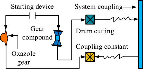
Figure 2. Coupling model of GR and GO in gearbox.
In Figure 2, the various components in the system are mutually constrained. To control meshing noise, the coupling system optimizes the geometric shape of the gears and reduces noise by minimizing the impact of gear meshing. Numerical simulation methods were used to analyze the mechanism of noise generation in the dynamic data of the transmission system. The aim was to identify the key gears responsible for noise generation. This method verifies the effective performance of the established system through simulation experiments, in which the interaction between the system and the environment is simulated through the simulation environment. The performance of the observation system in different situations is studied and compared with traditional methods. Its working state is analyzed as shown in Eq. 4.
In Eq. 4, the shape changes of the two gears are represented by
In Eq. 5, the rotation angle of the gear during operation is denoted as
In Eq. 6, the transmission power of the gear is denoted as
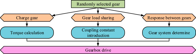
Figure 3. Flowchart of designing transmission ratio of gearbox by combining LS and GRO.
Figure 3 shows the transmission ratio design method of the gearbox. This study first optimizes the gear ratio of the gearbox to improve transmission performance, and adjusts the size of the gears to adapt to environmental conditions. In this process, GRO’s goal is to select the optimal gear ratio to provide optimal acceleration performance. When designing the transmission ratio of the gearbox, this study uses LS technology to consider the load situation of the gears, thereby providing a better working environment for the gears, as shown in Eq. 7.
In Eq. 7, the gear load at the current moment is denoted as
3.2 Construction of TMN control system based on GRO
To control the meshing noise of the gears in the gearbox during operation, this study designs a control strategy based on GR and LS based on the results of dynamic analysis. This study optimizes the structure of the gearbox by changing its working parameters, while controlling the time series of gear meshing process to weaken the propagation of meshing noise. This method reduces propagation loss by reducing the propagation path of noise, thereby reducing the impact range of noise. Its working principle is Figure 4.
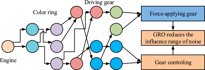
Figure 4. Working principle of dynamic analysis to reduce the influence range of noise.
In Figure 4, this study optimizes the path from the engine to the driving device on the power transmission route of the gearbox. On this propagation route, power is transmitted from the engine to the transmission shaft. It achieves power output through the meshing of gears with different particle sizes, thereby meeting the speed changing process of the gearbox. During this process, GRO can determine the gear operating characteristics of the gearbox, thereby reducing gear whistling during operation. Its calculation method is Eq. 8.
In Eq. 8,
In Eq. 9, the torque stiffness between gears is denoted as
Figure 5. Gearbox meshing noise control system combining GRO and SET.
Figure 5 shows a gear noise reduction system combining GRO and SET. To avoid complex mathematical models, this study first chose to directly measure the magnetic flux of the motor to achieve control. For the time-varying excitation signals in the system, this study implements the adjustment process of the feedback loop on the core of the direct torque control system. By processing the measured values of magnetic flux, precise control of the motor can be achieved, as shown in Eq. 10.
In Eq. 10,
In Eq. 11, the rotational adhesion ability between the applied gears is denoted as
In Eq. 12, the approaching speed of the simulated engineering is denoted as
Figure 6. Flow chart of controlling parameters of SET by gear speed regulation joint method.
The method chosen in this study for controlling this parameter is the combined gear speed control method. In Figure 6, this study adjusts the gear transmission ratio in the transmission system to change the external excitation applied to the system. This method can adjust the dynamic characteristics of the system to meet the requirements at different time intervals. For the SET-GRO system, the gear speed control joint method can adapt to the design requirements of the system. During this process, the parameter changes of the system are represented by Eq. 13.
In Eq. 13,
In Eq. 14, the position of the transmission power at a certain time is denoted as
In Eq. 15, the meshing noise of the gearbox is denoted as
4 Dynamic characteristics of coupled system SET-GRO in gear meshing noise
This study conducted experiments on the Gmnoi dataset to verify the control effect of the proposed SET-GRO system on gearbox gear meshing noise. In this dataset, this study collected a total of 28,561 sets of gearbox gear sets with different geometric sizes, containing various metal components. Considering the influence of environmental factors on the experimental results, this study conducted experiments on these gears with the same lubrication conditions and assembly accuracy.
4.1 Performance analysis of SET-GRO system for TMN
This study divided the data in the Gmnoi dataset into two groups in a 1:1 ratio to verify the learning performance and noise reduction performance of the system, respectively. As shown in Table 1, prior to the experiment, the equipment and parameters for the experiment were determined in this study.
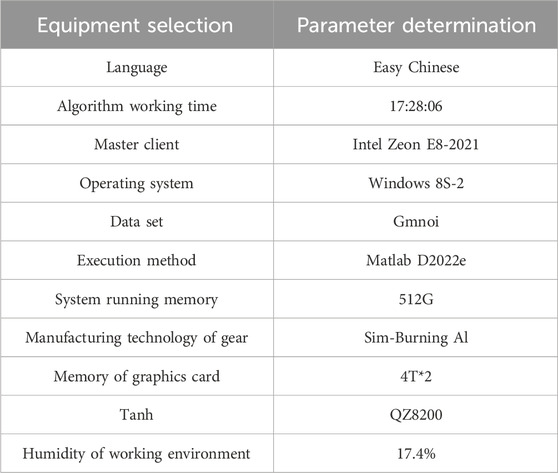
Table 1. Equipment selection and parameter determination in SET-GRO system verification experiment.
After determining the experimental parameters according to Table 1, for the model verification of the calculation process, this study conducted gear noise control experiments under different lubrication states. The SET-GRO system was compared with Long and Short Term Memory (LSTM) system, Quantum Genetic (QG) system, and GRO system to verify its superiority. The experimental results are shown in Figure 7.

Figure 7. Superiority experiment of SET-GRO system.
Figure 7A shows that in a low lubrication gear system, the meshing noise of the gears increases gradually as the gear particle size increases for all four systems. When the gear radius reaches 10.8 cm, the meshing noise level of the gear reaches its maximum, which is 742, 831, 923, and 976 in the four systems, respectively. This indicates that for gears under the same conditions, the gear meshing noise of the SET-GRO system is the smallest. In Figure 7B, the suppression effects of SET-GRO, GRO, LSTM, and QG systems on gear meshing noise are 98.4%, 95.8%, 93.5%, and 92.7%, respectively. This indicates that the SET-GRO system has the best noise reduction effect on low lubrication gear systems. But a single experiment cannot demonstrate the scalability of the system. To verify the noise reduction effect of the system in different environments, this study changed the external environment of the gearbox and conducted separate experiments to verify the noise control effect of the system. The results are shown in Figure 8.
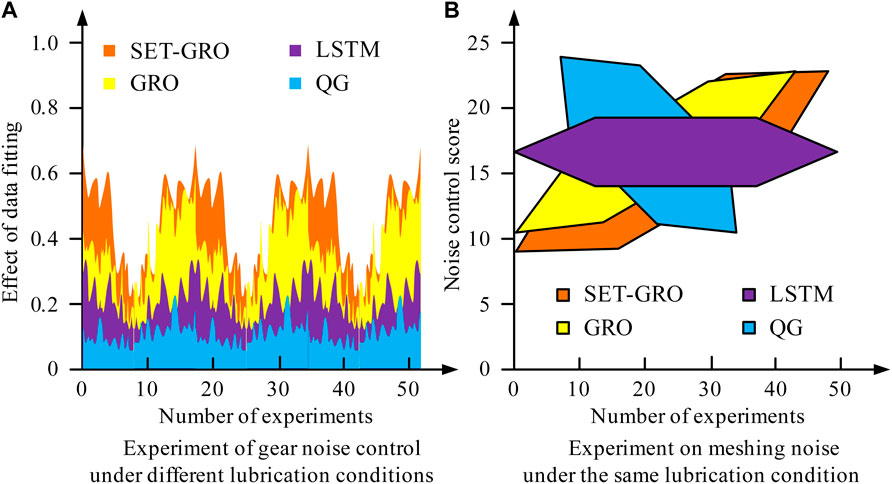
Figure 8. Experimental verification of noise effect of the system under different conditions.
Figure 8 compares the scalability of four systems. In Figure 8A, among the 50 experiments conducted, the SET-GRO system performs the best in noise control, with a value of 0.715. The experimental results of the other three systems are 0.618, 0.524, and 0.475, respectively. In Figure 8B, the control performance of the four systems for meshing noise is 47, 35, 28, and 11, respectively. This experiment can demonstrate the control performance of the SET-GRO system for small gear trains, but it cannot demonstrate the application effect of large gears. To verify it, this study conducted experiments on a large gear system, as shown in Figure 9.
Figure 9. Experimental study on gear meshing noise control of large gear system.
Figure 9 shows the control effect of the SET-GRO system in a large gear system. The SET-GRO system has the best noise reduction effect in large gear trains, with a noise reduction effect of 97.4%. This result can demonstrate the meshing noise control effect of the SET-GRO system in the same gear combination, but there are still shortcomings in experiments on gears of different materials, so further experiments are also needed.
4.2 Verification of TMN control effectiveness based on SET-GRO system
To compare the meshing noise control effect of the SET-GRO system in different material gear groups, this study changed the gear material while controlling the same gear particle size and lubrication degree. By calculating the gear meshing noise control under different conditions, experiments on the stability and robustness of the SET-GRO system were conducted. The stability experiment results of the system are shown in Figure 10.
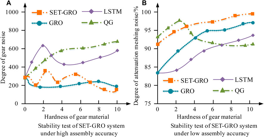
Figure 10. Stability test of SET-GRO system.
Figure 10 shows an experiment on the stability of the SET-GRO system. In Figure 10A, the noise control effect of all four systems increases with the increase of gear hardness. The highest performance of SET-GRO, GRO, LSTM, and QG systems are 623, 514, 406, and 423, respectively. In Figure 10B, the performance of the SET-GRO system is still superior in low precision gear systems. This indicates that the SET-GRO system can stably control the meshing noise of gears. This result is similar to that of Freisinger et al., 2024. To conduct experiments on its robustness, the composition materials of the gears were replaced in this study, as shown in Figure 11.
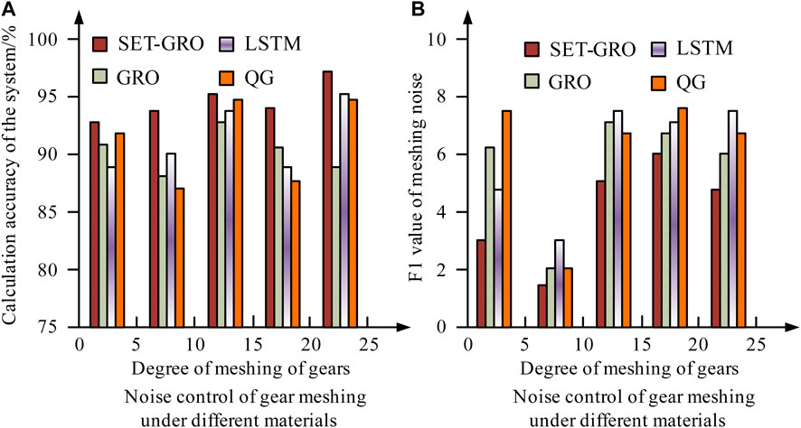
Figure 11. Robustness test of four systems for gear train.
In Figure 11A, the control effect of the four systems on meshing noise is directly proportional to the degree of gear meshing. The accuracy of the SET-GRO system is 97.2%, which performs the best among the four systems. Figure 11B shows that the F1 values of the four systems vary with the increase of gear meshing degree. However, the SET-GRO system consistently has the lowest F1 value among the four systems. Adamzadeh et al., 2023 got the same result. The experimental results indicate that the coupling system is highly robust in controlling gear meshing noise. It effectively addresses the defects present in the theoretical background and is suitable for optimizing gear meshing.
5 Conclusion
The development of the motor equipment manufacturing industry has attracted attention to the noise control of gearboxes. To denoise a wide range of data, this study introduced SET into GRO and generated a coupled system SET-GRO. The efficiency, accuracy, and robustness of the system were tested on the Gmnoi dataset and compared with the other three systems. When the lubrication effect of the gears was low, the meshing noise in the SET-GRO, GRO, LSTM, and QG systems was 742, 831, 923, and 976, respectively, indicating that the gear meshing noise in the SET-GRO system is the smallest. When operating in a highly lubricated environment, the SET-GRO system demonstrated a 98.4% effectiveness in reducing noise, indicating that the SET-GRO system can target different lubrication states of gears. In the case of different gear radii, the noise reduction effects of the four systems on large gear sets were 97.4%, 96.1%, 95.7%, and 95.2%, respectively, indicating that the system can target gear systems of different sizes. Under the condition of changing the gear material, the noise reduction effects of the four systems on aluminum gears were 623, 514, 406, and 423, respectively. When the gear material was iron, the SET-GRO system had a noise removal accuracy of 98.2% for the meshing system, which is the highest among the four systems. This indicated that the SET-GRO system had accuracy in controlling the meshing noise of the gearbox. As the manufacturing accuracy of the gearbox changed, the F1 values of SET-GRO, GRO, LSTM, and QG systems were 4, 8, 11, and 7, respectively. Experimental results have shown that the proposed SET-GRO coupling system has robustness and accuracy in controlling meshing noise, and is suitable for reducing noise pollution in transmissions. However, this study focuses solely on gear meshing under low-pressure conditions. Further research is needed to investigate gear meshing under high-pressure environments. This limitation is due to safety hazards for personnel in high-voltage environments, as well as the inability to process the excitation current generated during the experiment. Future research will address this limitation as equipment is upgraded.
Data availability statement
The original contributions presented in the study are included in the article/Supplementary material, further inquiries can be directed to the corresponding author.
Author contributions
LZ: Conceptualization, Writing–original draft. TW: Data curation, Validation, Writing–review and editing. CZ: Investigation, Methodology, Validation, Writing–review and editing.
Funding
The author(s) declare that no financial support was received for the research, authorship, and/or publication of this article.
Conflict of interest
The authors declare that the research was conducted in the absence of any commercial or financial relationships that could be construed as a potential conflict of interest.
Publisher’s note
All claims expressed in this article are solely those of the authors and do not necessarily represent those of their affiliated organizations, or those of the publisher, the editors and the reviewers. Any product that may be evaluated in this article, or claim that may be made by its manufacturer, is not guaranteed or endorsed by the publisher.
References
Adamzadeh, M., Enayati, M. H., Shamanian, M., and Khayambashi, P. (2023). Tribological behavior of Ni-Nb amorphous coating fabricated by mechanical alloying method. Tribol. Int. 179, 108151. doi:10.1016/j.triboint.2022.108016
Amin, S. N., Shivakumara, P., Jun, T. X., Chong, L., Zan, D. L. L., and Rahavendra, R. (2023). An augmented reality-based approach for designing interactive food menu of restaurant using android. Artif. Intell. Appl. 1 (1), 26–34. doi:10.47852/bonviewaia2202354
Charles, D. (2023). The lead-lag relationship between international food prices, freight rates, and Trinidad and Tobago's food inflation: a support vector regression analysis. Green Low-Carbon Econ. 1 (2), 94–103. doi:10.47852/bonviewglce3202797
Chaudhary, T., Siddiquee, A. N., Chanda, A. K., Ahmad, S., Anjum Badruddin, I., and A. Khan, Z. (2021). Multiple response optimization of dimensional accuracy of nimonic alloy miniature gear machined on wire edm using entropy Topsis andpareto anova. Comput. Model Eng. Sci. 126 (1), 241–259. doi:10.32604/cmes.2021.013368
Chen, D. C., Yang, R. S., Lu, S. W., and Guo, H. Y. (2022b). Application of mold flow analysis to the study of plastic gear rack injection molding warpage. Trans. Can. Soc. Mech. Eng. 47 (1), 15–25. doi:10.1139/tcsme-2022-0048
Chen, Y. L., Liu, Q. Y., and Li, X. (2022a). Multiphysics coupled simulation of electrolytic machining of toothed grooves of contrate gear. Trans. Tech. Publ. Ltd. 1078 (2), 23–29. doi:10.4028/p-g85mft
El-Hadj, A. A., and Abd Rahim, S. Z. B. (2020). Optimization of an external gear pump using response surface method. J. Mech. 36 (4), 567–575. doi:10.1017/jmech.2020.7
Esterhuizen, G., Tulu, B., Gearhart, F., Dougherty, H., and Van Dyke, M. (2021). Assessing support alternatives for longwall gateroads subject to changing stress. Int. J. Min. Sci. Technol. 31 (1), 103–110. doi:10.1016/j.ijmst.2020.12.016
Freisinger, M., Rojacz, H., Pichelbauer, K., Trausmuth, A., Trummer, G., Six, K., et al. (2024). Comparative study on the influence of initial deformation and temperature of thermally induced white etching layers on rail wheels. Tribol. Int. 191, 109159. doi:10.1016/j.triboint.2022.107990
Gorla, C., Rosa, F., and Conrado, E. (2020). Bending fatigue strength of case carburized and nitrided gear steels for aeronautical applications. Int. J. Appl. Eng. Res. 12 (21), 11306–11322.
Hou, L., Lei, Y., Fu, Y., and Hu, J. (2020). Effects of lightweight gear blank on noise, vibration and harshness for electric drive system in electric vehicles. Proc. Institution Mech. Eng. Part K J. Multi-Body Dyn. 234 (3), 447–464. doi:10.1177/1464419320915006
Ismail, S. A., Raphael, W., and Durand, E. (2021). Analysis of the structural response of Beirut port concrete silos under blast loading. Archives Civ. Eng. 67 (3), 619–638. doi:10.24423/ace.2021.138074
Li, X., Liu, X., Li, X., He, W., and Guo, H. (2022). Improved method for analysing the dynamic response of gear transmission systems. Eng. Comput. 39 (9), 3232–3254. doi:10.1108/ec-08-2021-0500
Liu, Y., Li, Y., Ma, L., Chen, B., and Li, R. (2022). Parametric design approach on high-order and multi-segment modified elliptical helical gears based on virtual gear shaping. Proc. Institution Mech. Eng. Part C J. Mech. Eng. Sci. 236 (9), 4599–4609. doi:10.1177/09544062211058396
Mo, S., Song, Y., Feng, Z., Song, W., and Hou, M. (2022). Research on dynamic load sharing characteristics of double input face gear split-parallel transmission system. Proc. Institution Mech. Eng. Part C J. Mech. Eng. Sci. 236 (5), 2185–2202. doi:10.1177/09544062211026349
Mo, S., Yue, Z., Feng, Z., Shi, L., Zou, Z., and Dang, H. (2020). Analytical investigation on load-sharing characteristics for multi-power face gear split flow system. Proc. Institution Mech. Eng. Part C J. Mech. Eng. Sci. 234 (2), 676–692. doi:10.1177/0954406219876954
Nsugbe, E. (2023). Toward a self-supervised architecture for semen quality prediction using environmental and lifestyle factors. Artif. Intell. Appl. 1 (1), 35–42. doi:10.47852/bonviewaia2202303
Yadav, R. D., Singh, A. K., and Arora, K. (2020). Parametric analysis of magnetorheological finishing process for improved performance of gear profile. J. Manuf. Process. 57, 254–267. Sep. doi:10.1016/j.jmapro.2020.06.024
Yao, J. L., Shu, X. B., and Ren, G. X. (2022). A free-interface component mode synthesis of moving contact multibodies and its application to gear contacts. Int. J. Numer. Methods Eng. 123 (14), 3317–3343. doi:10.1002/nme.6970
Zhang, H., and Shen, X. (2020). A dynamic tooth wear prediction model for reflecting “two-sides” coupling relation between tooth wear accumulation and load sharing behavior in compound planetary gear set. Proc. Institution Mech. Eng. Part C J. Mech. Eng. Sci. 234 (9), 1746–1763. doi:10.1177/0954406219900085
Keywords: gear response, load distribution, gear order, coupling system, noise control, gear meshing, transmission, stiffness examination
Citation: Zhang L, Wan T and Zhang C (2024) The influence of gear load distribution based on coupled systems on gearbox meshing noise. Front. Mech. Eng 10:1362431. doi: 10.3389/fmech.2024.1362431
Received: 28 December 2023; Accepted: 06 March 2024;
Published: 02 April 2024.
Edited by:
Florent Ravelet, Arts et Metiers Institute of Technology, FranceReviewed by:
Zhongliang Xie, Northwestern Polytechnical University, ChinaJán Dižo, University of Žilina, Slovakia
Copyright © 2024 Zhang, Wan and Zhang. This is an open-access article distributed under the terms of the Creative Commons Attribution License (CC BY). The use, distribution or reproduction in other forums is permitted, provided the original author(s) and the copyright owner(s) are credited and that the original publication in this journal is cited, in accordance with accepted academic practice. No use, distribution or reproduction is permitted which does not comply with these terms.
*Correspondence: Teng Wan, tengteng5116@126.com