Lean ammonia-fueled engine operation enabled by hydrogen-assisted turbulent jet ignition
 Shawn A. Reggeti
 William F. Northrop
- T.E. Murphy Engine Research Laboratory, Department of Mechanical Engineering, University of Minnesota, Minneapolis, MN, United States
Anhydrous ammonia (NH3) use in internal combustion engines represents a zero-carbon energy solution that is fully sustainable if NH3 is generated renewably. An active hydrogen-fueled pre-chamber to induce turbulent jet ignition is investigated in this work as a means to enhance ignition energy and turbulent flame speed in an NH3 fueled engine. The strength of the turbulent jets, and thus their effectiveness in igniting the main-chamber and enhancing combustion, is highly dependent on pre-chamber equivalence ratio and hydrogen fraction. Local pre-chamber mixtures are varied in the present study by investigating a range of pre-mixed intake NH3-air equivalence ratios (ϕ = 0.5–1) under a consistent hydrogen direct injection strategy in the pre-chamber. Additionally, given the knock-resistance of NH3, multiple compression ratios were studied to investigate the impact on efficiency, emissions, and the combustion process. Results show a clear trade-off where leaner intake equivalence ratios enhance the reactivity of the pre-chamber (greater local hydrogen fraction and closer to stoichiometry) but reduce the reactivity of the main-chamber (lean and slow flame speed). Spark timing optimizes the trade-off under a fixed injection strategy; advancing spark provides more time for combustion to occur in the main-chamber but inhibits pre-chamber reactivity for a less energetic ignition of the main chamber. Optimal indicated thermal efficiency and minimum unburned NH3 and N2O emissions occur around 0.7–0.8 equivalence ratio for all compression ratios. Conversely, NOx is highest at these equivalence ratios but could theoretically be eliminated using selective catalytic reduction aftertreatment using the NH3 present in the exhaust.
1 Introduction
Renewable energy is the fastest growing energy source, offsetting global dependence on fossil fuels and reducing greenhouse gas emissions (Nalley and LaRose, 2022). E-fuels like hydrogen (H2) and anhydrous ammonia (NH3) can be used for renewable energy storage, distribution, and utilization with applications in grid stability, industrial processes, and vehicles. Ammonia is of particular interest as a carbon-free fuel for internal combustion engines (ICEs) because of its liquid storage capabilities at modest pressure (8.6 bar) or temperature (240 K) and its established worldwide production and distribution (Chehade and Dincer, 2021). Primary challenges for ammonia-fueled ICEs are the fuel’s slow laminar flame speed, high ignition energy, and narrow flammability limits (Kobayashi et al., 2019). Additionally, fundamental understanding and innovative combustion strategies are needed to achieve low emissions of unburned NH3 and nitrogen oxides, particularly N2O.
Previous studies with spark ignition (SI) engines have blended ammonia with a more reactive fuel, such as hydrogen, to both enhance the ignitability of the mixture and increase flame speed such that the flame front has sufficient time to propagate across the combustion chamber (e.g., Lhuillier et al., 2020; Koike et al., 2021). Others have shown that increasing the compression ratio (16–20:1) of SI engines achieves stable operation with 100% NH3 fuel. Results suggest that in pure ammonia-fueled engines, the flame partially propagates across the combustion chamber, preheating the unburned gases to a point of auto-ignition (Mounaïm-Rousselle et al., 2022; Reggeti et al., 2023), a mode known as spark-assisted compression ignition (SACI) (Robertson and Prucka, 2019). Compression ignition (CI) of 100% NH3 requires a difficult-to-achieve compression ratio of 35:1 (Cornelius et al., 1966), therefore a high cetane fuel (e.g., diesel) has been used as a pilot fuel to ignite a fumigated ammonia-air mixture; partially reforming the ammonia to hydrogen improves performance and reduces the minimum required diesel energy fraction (Gill et al., 2012; Kane and Northrop, 2021). Each of these approaches to burning ammonia in engines comes with their respective challenges. In a conventional SI engine architecture, 10%–20% hydrogen energy fraction is needed to operate without misfiring across the operating map, meaning that either hydrogen must be directly supplied from a storage tank or significant onboard ammonia reforming is needed (Frigo and Gentili, 2013; Mounaïm-Rousselle et al., 2021). Increasing the compression ratio in SI engines lowers the hydrogen requirement but tends to produce higher unburned ammonia emissions as a greater portion of the fuel becomes trapped in crevices (Westlye et al., 2013). Additionally, spark plugs may face durability issues when igniting at high pressures. CI engines operated with ammonia fumigation and a pilot fuel represents a simple retrofit solution for existing engines to partially displace dependence on fossil fuels, but is not carbon-free. Management of emissions from dual-fuel CI engines is challenging because NOx and particulate matter increase, while unburned ammonia and N2O are also elevated. Excessive N2O emissions from ammonia engines offset the benefit of CO2 reduction (Gill et al., 2012) because N2O has 298 times the global warming potential of CO2.
Pre-chamber turbulent jet ignition (TJI) engines are an alternative to traditional CI or SI architectures and have been a recent research topic for ammonia fueled ICEs. TJI refers to igniting a small portion of the combustible mixture in a pre-chamber which is connected to the engine cylinder by several nozzles. After igniting the pre-chamber mixture with a spark plug, turbulent flames and/or hot combustion gases are ejected into the engine cylinder, igniting the main charge (Rajasegar et al., 2023). This strategy has been shown to extend the lean flammability limit of natural gas and hydrogen engines (Distaso et al., 2020; Balasubramani et al., 2023), suggesting possibility of extending the lean operating limit of NH3 in engines to achieve greater thermal efficiency. Additionally, TJI increases turbulent kinetic energy at the flame front leading to a faster turbulent flame speed (Silva et al., 2022) and deposits more ignition energy at distributed sites throughout the main chamber (Gholamisheeri et al., 2017).
Experiments in a constant-volume chamber (Liu et al., 2024) and in a single-cylinder engine (Liu et al., 2023a; Liu et al., 2023b; Liu et al., 2023c) show that TJI for ammonia ICEs reduced burning duration, improved combustion stability, and extended lean operation limit. Directly injecting a more reactive fuel into the pre-chamber has the advantage of increased indicated thermal efficiency (ITE) compared to SI mode (Liu et al., 2023c) while injecting ammonia into the pre-chamber decreases ITE compared to SI mode (Liu et al., 2023b). TJI has been shown to reduce H2 consumption when compared to premixed NH3-H2 mixture ignited by a traditional spark-plug (Liu et al., 2024). Such fuel saving would place less demand on on-board catalytic dissociation of NH3 for H2 generation, or would allow for a downsized hydrogen storage system. As an additional consideration, pre-chamber performance is sensitive to overall mixture preparation including trapped combustion residuals from the previous cycle (Liu et al., 2023c; Rajasegar et al., 2023).
This work investigates the performance of a single cylinder engine with port-injected ammonia and an active hydrogen-fueled pre-chamber. The local pre-chamber mixture is modified by sweeping the equivalence ratio of the inducted ammonia-air mixture. Not only is stable operation achieved with very lean intake equivalence ratio, but insights for emissions formation and favorable improvements to ITE are noted at lean conditions. Additionally, three compression ratios were tested (12:1, 16:1, 20:1) which show evidence of auto-ignition phenomena after initial flame propagation.
2 Experimental setup
Experiments were conducted using a Waukesha Cooperative Fuel Research (CFR) octane rating engine (82.5 mm bore x 114.3 mm stroke), modified for pre-chamber operation. A schematic of the CFR engine combustion chamber (Figure 1) shows that an in-cylinder pressure transducer (Kistler Type 6056A) is mounted in the left side port and the pre-chamber is located in the pickup port on the right. The pre-chamber, provided by MAHLE Powertrain, is actively fueled by a H2 gas injector (BorgWarner). The pre-chamber mixture is ignited by a spark plug (NGK 9356), and pre-chamber pressure is measured by a second pressure transducer (Kistler Type 6056A). The pre-chamber volume is nominally 1 cm3 and connected to the engine cylinder by three 1.5 mm diameter nozzles. The design of the pre-chamber was based on those developed for conventional fuels (i.e., gasoline and natural gas) and therefore represents a baseline experiment for NH3-fueled engines. Other design features are constrained by the CFR engine geometry. For instance, the asymmetric arrangement of the three pre-chamber nozzles was required to direct the turbulent jets towards the center of the combustion chamber from the pick-up port. Further optimization of the pre-chamber design for NH3 fuel and engine type may be the topic of future work.
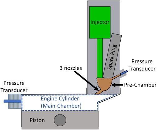
FIGURE 1. Schematic of engine and pre-chamber.
During engine operation, combustion is initiated by the spark plug in the pre-chamber producing turbulent jets of hot gases that emerge from the pre-chamber nozzles, igniting the cylinder mixture at the right side of the bore in Figure 1. The flame front then propagates across the entire cylinder bore, rather than radially from the center as in most production engines, pressurizing and heating the unburned portion of the mixture over a longer time period which increases the likelihood of auto-ignition.
A range of compression ratios and intake mixtures were tested at an engine speed of 900 RPM; these parameters are summarized in Table 1. Dry air from a centralized compressor and pressure swing absorption system (to remove moisture and CO2) was metered to the engine intake by a Brooks 5853E Mass flow controller (MFC). A 113 L tank was used as a plenum resonator to dampen pressure pulsations from the engine. Intake air temperature was controlled by an inline electric heater (Omega AHPF-101). Gaseous NH3, controlled by a Brooks 5851 MF C, was added the intake air mixture ≈30 cm upstream of the intake valve for a homogeneous NH3-air mixture to be inducted into the engine. The equivalence ratio of this mixture was varied by decreasing the ammonia flow rate and increasing the air flow rate to maintain equivalent intake pressure for all fueling conditions. High-speed intake pressure was measured near the intake valve using a production manifold absolute pressure (MAP) sensor. The piezoelectric cylinder and pre-chamber pressure transducers were pegged to the MAP sensor value at bottom dead center (BDC) after the intake stroke. During the compression stroke H2 gas was directly injected for a 2 ms duration into the pre-chamber with a constant dwell of 50° before spark timing (°bST). Compressible flow theory indicates that hydrogen flow is choked in all test cases, thus the mass of hydrogen deposited is constant for each case. Choked flow was verified with a Coriolis mass flow meter (Alicat CODA) which showed constant hydrogen flow rates when injecting into pre-chamber pressures below ≈20 bar (true for all cases). Since hydrogen flow remains constant but ammonia flow varies to achieve different equivalence ratios, the hydrogen fuel fraction ranges from 5.5% at stoichiometric intake to 11.9% at ϕ = 0.5. Two spark timings were considered for each condition: fixed spark timing at 25°before top dead center (bTDC) and at MBT spark timing for optimal gIMEP to the nearest 5°crank angle.
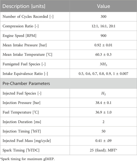
TABLE 1. Engine specifications and operating conditions.
Slow-speed pressure/temperature data acquisition and high-speed experiment control, including spark timing and H2 direct injection, were managed using a cRIO-9074 coupled to LabVIEW. The average conditions and standard deviations across experiment cases are noted in Table 1. Simultaneously, a National Instruments PXI-1042 coupled to a separate LabVIEW program acquired high-speed pressure data in the cylinder, pre-chamber, and intake port. Results presented in this work are averages from 300 consecutive engine cycles at each condition. Emissions were measured using an AVL i60 SESAM FT emissions bench featuring a Fourier transform infrared spectrometer (FTIR) to measure nitrogen-based species (e.g., NH3, NOx, and N2O) and a paramagnetic oxygen detector. Emissions were recorded at a 1 Hz sample rate over 1 minute of steady state operation. Since the NH3 measurement range of the FTIR was limited to 1,000 ppm, the exhaust was diluted with compressed air. The dilution ratio was quantified by the ratio of oxygen in undiluted versus diluted exhaust. Uncertainty of emissions measurements are dominated by the uncertainty in dilution ratio which are computed as described in our previous work (Reggeti et al., 2023).
3 Results
Overall engine performance is summarized by indicated thermal efficiency (ITE) and gross indicated mean effective pressure (gIMEP) at MBT spark timing in Figure 2. All compression ratios show similar trends with varied intake equivalence ratio, where maximum ITE occurs around 0.7–0.8 equivalence ratio. Decreasing equivalence ratio corresponds to a decrease in gIMEP. Intake pressure was consistent for all cases, thus the fuel energy-in necessarily decreased with equivalence ratio. These engine performance parameters are impacted by pre-chamber reactivity (which drives turbulent jet ignition), and the subsequent combustion process in the main-chamber, which are coupled phenomena.
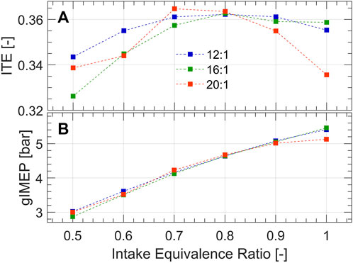
FIGURE 2. (A) Indicated thermal efficiency and (B) gross indicated mean effective pressure.
3.1 Pre-chamber reactivity
Figure 3 shows the pre-chamber and cylinder pressure traces at 12:1 compression ratio with fixed spark timing (−25°aTDC). H2 injection into the pre-chamber starts at −75°aTDC and causes a slight rise in pre-chamber pressure, forcing some of the NH3-air mixture, residuals from the previous cycle, and hydrogen into the main chamber (Figure 3B). After the end of injection, the piston continues to rise, compressing ammonia, hydrogen, and air into the pre-chamber. Then the pre-chamber mixture is ignited by the spark plug, causing a pressure rise in the pre-chamber, which is a function of the burn rate and pre-chamber geometry. The maximum difference between pre- and main-chamber pressures (ΔPmax) are shown by zoomed in section (A) of Figure 3, where largest difference in pressures occurs for the leanest intake equivalence ratio. These results indicate that the pre-chamber burn rate is greatest for the lean intake condition. The excess air in the intake charge seems to enhance the reactivity of the pre-chamber by decreasing the local ammonia fraction, and converging local equivalence ratios towards stoichiometry. In contrast, the stoichiometric intake condition introduces more ammonia into the pre-chamber, decreasing hydrogen fraction and creating a more fuel-rich equivalence ratio, which results in slower burning and a reduced ΔPmax. Turbulent jets are driven by the pressure difference and emerge into the main-chamber, igniting it and initiating flame propagation across the cylinder bore. Although ϕ = 0.6 in Figure 3 had the greatest ΔPmax, and thus the most potent and distributed turbulent jets for main-chamber ignition, the main-chamber pressure was much lower than the other cases since the flame speed in the main-chamber was compromised by the excess air, leading to incomplete combustion.
FIGURE 3. Pre-chamber and cylinder pressure traces at 12:1 compression ratio at fixed spark timing (25°bTDC). Increase in pre-chamber pressure is highlighted during (A) pre-chamber burn immediately following spark timing, and (B) the hydrogen injection process.
Figure 4 compares the turbulent jet strength across different conditions using the maximum difference in pre- and main-chamber pressures (ΔPmax) as a metric. Each subplot shows the results of a given compression ratio (12:1, 16:1, and 20:1) over a range of equivalence ratios at fixed spark timing (25°bTDC) and at MBT spark timing. The cases represented in Figure 3 are circled in Figure 4A. At a fixed spark timing, ΔPmax increases with decreasing equivalence ratio suggesting higher pre-chamber reactivity because of decreased ammonia fraction and closer-to-stoichiometric equivalence ratios. At MBT spark timing, ΔPmax generally increases as equivalence ratio is decreased from 1 to 0.8, but then remains somewhat consistent as equivalence ratio continues to decrease. At 12:1 (Figure 4A), lean equivalence ratios require a more advanced timing for optimal gIMEP, sacrificing pre-chamber reactivity for additional time to propagate the flame in the main chamber. Conversely, at 20:1 (Figure 4C), most cases require a retarded spark timing to optimally phase combustion, which occurs more rapidly at high compression ratio with the possibility of an auto-ignition event in the main-chamber. The 16:1 compression ratio (Figure 4B) represents a sort of middle ground where MBT spark timing is slightly retarded for ϕ > 0.7 and advanced for the most lean cases.
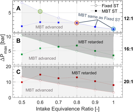
FIGURE 4. The maximum difference between pre-chamber and main-chamber pressures following ignition for compression ratios (A) 12:1, (B) 16:1, and (C) 20:1. The conditions of pressure traces in Figure 3 are circled in (A). The shaded regions indicate whether spark timing was advanced or retarded for MBT in comparison to the fixed spark timing of 25°bTDC.
3.2 Combustion analysis
Figure 5 shows the net heat release rates (NHRRs) for the three compression ratios tested where columns of subplots from left to right correspond to 12:1, 16:1, and 20:1, respectively. The top row of subplots in Figure 5 show the cases with fixed spark timing (25°bTDC) and the bottom row shows the cases with MBT spark timing. The corresponding figure containing the pre- and main-chamber pressure traces can be found in the Supplementary Material. Within each plot, NHRRs are shown along with the crank angle of 50% total heat release (CA50, dashed vertical lines), illustrating the burn rate and combustion phasing, respectively. Generally, NHRR exhibits an initial peak soon after spark timing which constitutes the pre-chamber burn and the jet emergence into the main-chamber; thereafter, heat is released in the main-chamber as the flame consumes the remaining fuel-air mixture. For the 12:1 cases (left column, Figure 5), the NHRRs all appear parabolic, or with a slight plateau, indicating that the heat release is gradual and primarily driven by flame propagation. At increased compression ratios (middle and right columns, Figure 5) most conditions exhibit a dual-peak heat release, where combustion occurs initially as flame propagation, but then the rate of heat release increases drastically around TDC by a supposed auto-ignition event.
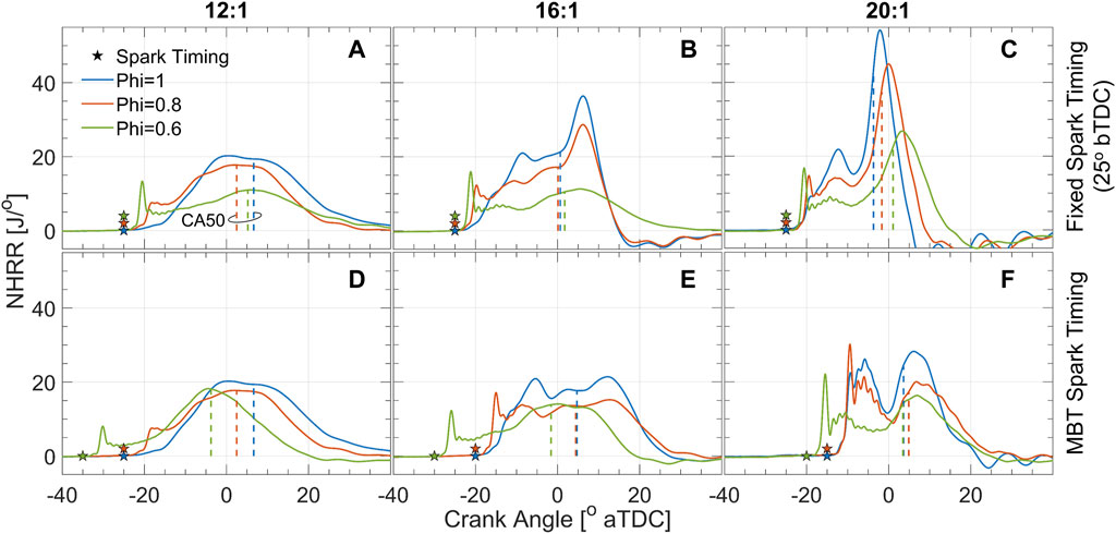
FIGURE 5. NHRR for compression ratios 12:1, 16:1, and 20:1 (first, second, and third columns, respectively) at fixed spark timing (top row) and MBT spark timing (bottom row). CA50 is shown by the dashed vertical lines. The corresponding pressure traces for pre- and main-chamber can be found in the Supplementary Material.
At 12:1 compression ratio, the MBT spark timing happens to be the same as the fixed spark timing (25°bTDC) for the ϕ = 1 and ϕ = 0.8 cases. The NHRR for the stoichiometric case begins gradually and develops into a plateau-like shape as the flame propagates across the cylinder. The ϕ = 0.8 case is ignited by stronger turbulent jets, as shown in Figures 3, 4, thus the NHRR initially rises quickly with a small peak around −18°aTDC indicating a faster, more energetic ignition compared to the stoichiometric case. Then the main chamber burns by flame propagation, characterized by the parabolic NHRR (Figure 5A). Interestingly, CA50 is more advanced for the ϕ = 0.8 case compared to ϕ = 1, suggesting that the stronger turbulent jets and more energetic ignition compensate for the slower flame speed. The ϕ = 0.6 case at the fixed spark timing of 25°bTDC (Figure 5A) shows a strong initial peak in NHRR, but heat release from the slowly propagating flame is poor. Advancing the spark timing to 35°bTDC yields MBT (Figure 5D) where the magnitude of the initial NHRR spike is reduced slightly, but there is sufficient time for combustion to be completed in the main chamber. As a result of advancing spark timing, the CA50 for the ϕ = 0.6 case is also most advanced compared to the other mixtures at MBT spark timing.
A dual-peak NHRR is apparent for several cases when the compression ratio is increased to 16:1 (middle column, Figure 5). At fixed spark timing (Figure 5B) the ϕ = 1 and ϕ = 0.8 cases show somewhat gradual NHRRs until ≈ 2–3°aTDC, at which point both cases show a rapid increase in NHRR. This pattern of heat release is comparable to a SACI operating mode (Robertson and Prucka, 2019) where this second peak in NHRR corresponds to auto-ignition of the unburned portion of the gas mixture. The ϕ = 0.6 case at fixed spark timing does not exhibit such an obvious second peak in the cycle-averaged NHRR, suggesting that the ignition delay is longer than the engine residence time, thus heat is released by flame propagation. Similar trends are noted for MBT spark timing at 16:1 compression ratio (Figure 5E). Spark timing is retarded slightly for the ϕ = 1 and ϕ = 0.8 cases which cause the secondary peak in NHRR to be delayed to ≈ 7–8°aTDC and less prominent in magnitude. On the other hand, spark timing was advanced slightly for the ϕ = 0.6 case; a strong initial spike in NHRR is noted immediately after spark from TJI and then a parabolic heat release rate suggests flame propagation mode without auto-ignition.
All of the 20:1 compression ratio cases (right column, Figure 5) show NHRRs with clear secondary peaks which correspond to auto-ignition events in the main chamber. The ϕ = 1 case at fixed spark timing (Figure 5C) shows a gradual increase in NHRR after spark until the first peak at around −12°aTDC. After a slight decrease in NHRR, it then increases rapidly to greater than 50 J/° by a strong auto-ignition event. Interestingly, the ϕ = 0.8 and ϕ = 0.6 cases seem to auto-ignite at about the same crank angle, but peak NHRRs occur later and of lower magnitude. For MBT (Figure 5F), spark timing is retarded for all equivalence ratios to delay auto-ignition and reduce the magnitude of the second NHRR peak. As a result, the local minimums between the first and second NHRR peaks occur around TDC and the auto-ignition heat releases occur almost entirely during the expansion stroke. Thus, overall combustion phasing occurs later for MBT spark timing as shown by CA50 which is ≈5°aTDC for all equivalence ratios. Interestingly, the local minimum in NHRR between the first and second peaks (around TDC) in Figure 5F is lower than at the 16:1 compression ratio (Figure 5E). Such a local minimum is non-existent in the 12:1 cases. It is probable that this decrease in NHRR is caused by a partial quenching of the propagating flame as the piston approaches TDC, which forms a narrow channel between the flat-top piston and the firedeck. The decrease in NHRR is more dramatic at increased compression ratios since the distance between the piston and the firedeck decreases. In fact, at 20:1 compression ratio there is only ≈5.4 mm between the two surfaces, which would lead to greater heat losses and quenching as the flame propagates.
Although these results suggest auto-ignition phenomena, ringing intensity remains low (
3.3 Emissions
Key emissions from the experiments are shown in Figure 6. Unburned NH3 emissions (Figure 6A) are lowest across all intake mixtures at the 12:1 compression ratio. This result is in agreement with previous studies (Westlye et al., 2013; Mounaïm-Rousselle et al., 2022) which attribute the increased NH3 emissions to increased cylinder pressures at elevated compression ratios, forcing more of the unburned gas mixture into engine crevices. Additionally, a quenching mechanism through the narrow clearance volume at TDC, as previously discussed, is more significant at increased compression ratios and may contribute to NH3 emissions. As for NH3 trends with intake equivalence ratio, minimum NH3 emissions are achieved at ϕ = 0.8 for the 12:1 compression ratio. This result contradicts the intuition that decreased equivalence ratio will have lower combustion temperatures, slower flame propagation, and will not burn as close to the engine walls; all of which point to increased ammonia emissions with decreasing equivalence ratio. On the other hand, decreased equivalence ratio means lower ammonia fraction in the gases trapped in the engine crevices and greater pre-chamber reactivity with improved ignition of the main chamber; both of which would decrease ammonia emissions. It appears that these competing factors are optimized at ϕ = 0.8 for the 12:1 case. For the increased compression ratios, NH3 emissions are fairly consistent to slightly decreasing with leaner intake equivalence ratios which suggests that lower ammonia fraction in the crevices and improved pre-chamber reactivity are dominating factors for ammonia emissions at high compression ratio.
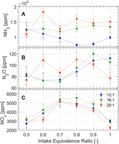
FIGURE 6. Emissions measurements of (A) NH3, (B) N2O, and (C) NOx.
Figure 6B shows that minimum N2O emissions occur around ϕ = 0.7 for 12:1 and 16:1 compression ratios, but that the trend is somewhat random for the 20:1 compression ratio. These trends at 12:1 and 16:1 compression ratio can be explained by previous work which investigated nitrogen-based emissions of ammonia combustion at engine-like conditions a 0-D chemical reactor (Northrop, 2023). A re-creation of the emissions contours in ϕ-T space proposed by Northrop is presented in Figure 7, which considers ammonia combustion at 20 bar for 1 ms residence time using the mechanism proposed by Stagni et al. (2020). The ammonia-air mixtures investigated in this study are pre-heated to 600–1200 K by compression prior to ignition yielding adiabatic flame temperatures of 1700–2150 K for ϕ = 0.5 and 2,300–2,700 for ϕ = 1, as shown in Figure 7. Therefore, aside from the most lean equivalence ratio where N2O formation can be explained by cool flame temperatures, these experimental results imply that N2O must form elsewhere in the combustion chamber besides the propagating flame front. One possible formation mechanism, which is supported by the analysis of NHRR in Sec. 3.2, is by flame quenching on the engine walls and heat transfer near the walls. As the flame propagates, heat losses likely form a temperature gradient in the flame front where temperatures decrease near the walls to form N2O locally by low temperature combustion. Immediately next to the walls, flame quenching occurs where N2O, an intermediate of the NH3 combustion mechanism (Kobayashi et al., 2019), becomes frozen in the combustion products. The effect of local low-temperature combustion and quenching is represented by the green highlighted region in Figure 7. Another formation pathway may manifest during during the expansion stroke when the unburned gases (NH3 and air) are released from the crevices to induce the thermal de-NOx mechanism (the reduction of NOx to N2 and N2O in the presence of NH3). However, 0-D analysis suggests that this pathway is insignificant by comparison to low-temperature zones and quenching (Northrop, 2023).
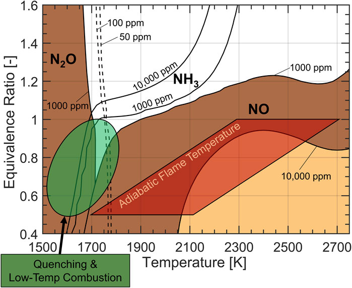
FIGURE 7. N2O, NO, and NH3 in ϕ-T space for ammonia combustion at 20 bar and 1 m residence time in a 0-D reactor. Emissions formation in the engine experiments are driven by the two highlighted regions.
Fuel bound nitrogen opens an additional pathway for NOx formation, causing it to form with shorter residence time at lower temperatures compared to hydrocarbon fuels (Westlye et al., 2013; Ryu et al., 2014). Figure 6C shows that NOx emissions are generally high and have an opposite trend to the previously discussed emissions, peaking at slightly lean equivalence ratios. Figure 7 shows that the 10,000 ppm contour of NOx intersects most with the adiabatic flame temperature envelope at equivalence ratios of 0.7–0.9, which correspond to the highest NOx emissions in the experiment shown in Figure 6C. This suggests that the propagating flame front, approximated by the adiabatic flame temperature, is likely where NOx forms. NOx emissions do not exceed 6,000 ppm in any of the experiments since low-temperature combustion regimes and quenching likely occur near the walls, resulting in an overall lower concentration of NOx in the engine exhaust.
Given the high NOx emissions, it is likely that a NH3-fueled internal combustion engine will require a SCR catalyst to keep NOx emissions within legislated limits. The unburned ammonia in the exhaust can be utilized as a NOx reductant where a NOx to NH3 ratio of unity is ideal to fully mitigate both species. This ratio is shown in Figure 8A. In all test cases, NOx could be fully mitigated since there is an excess of NH3 available. However, ϕ = 0.8 at the 12:1 compression ratio stands out as it is closest to unity whereby NOx could be completely mitigated along with ≈70% reduction in NH3.
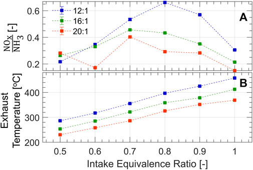
FIGURE 8. (A) Ratio of NOx to NH3; unity is optimal for complete destruction of both species. (B) Exhaust temperature shows that SCR lightoff could occur in the optimal range of 300–450°C.
Sufficient heat is produced by the combustion process to achieve SCR light-off temperatures of 300°C–450°C, as evidenced by Figure 8B. The exhaust temperature is measured ≈10 cm downstream of the exhaust valve, assessing the potential for a close-coupled catalyst. Equivalence ratios above 0.6–0.7 are suitable at the presented engine conditions to heat the catalyst. These results suggest that a production engine with further optimization (e.g., centrally mounted pre-chamber, and fewer engine crevices compared to the CFR) could be tuned to produce the proper ratio of NOx and NH3 and mitigate both of these emissions passively over an SCR catalyst. Additional, optimization of the in-cylinder combustion process is needed to better mitigate engine out N2O.
4 Conclusion
An ammonia fueled engine was investigated with lean intake equivalence ratios, enabled by a hydrogen assisted pre-chamber ignition system. Under a fixed hydrogen direct injection strategy to the pre-chamber, intake equivalence ratios of ammonia-air mixtures as low as 0.5 achieved reasonable ITE with low covariance. The present study resulted in the following conclusions:
• Pre-chamber reactivity is enhanced by decreasing the intake equivalence ratio thereby strengthening the turbulent jets which emerge to ignite the main chamber. The increased effectiveness of TJI at lean conditions is counterbalanced by decreased flame speed in the main chamber.
• Increasing compression ratio leads to a potential auto-ignition event in the main-chamber which accelerates the rate of heat release. Typical problems with auto-ignition (e.g., excessive cylinder pressure, high heat losses, and ringing) are not pronounced with ammonia combustion at MBT spark timing.
• A slowdown in NHRR for the high compression ratio cases suggests partial flame quenching, as the flame propagates through the narrow channel between the piston and the firedeck.
• Unburned ammonia emissions are the lowest for the lowest compression ratio case at slightly lean intake conditions. Increased compression ratios exhibit increased unburned ammonia emissions which decline slightly with decreased equivalence ratio. Combustible mixture trapping in the crevices and flame quenching in the small TDC volumes may contribute to the elevated NH3 emissions.
• N2O emissions are driven by cool spots, quenching, incomplete combustion, and the thermal de-NOx mechanism. The present work provides evidence that N2O does not form in the propagating flame front (except for very lean conditions) but rather forms primarily near the walls by low-temperature combustion and quenching.
• NOx emissions are generally high and peak at slightly lean equivalence ratios for all compression ratios. The ratio of NOx to NH3 along with exhaust temperatures in the present study suggest that NOx could be completely mitigated over a passive SCR catalyst while significantly reducing NH3 emissions. Tuning this ratio by controlling the combustion process in a production engine could effectively mitigate both NOx and NH3.
Data availability statement
The raw data supporting the conclusions of this article will be made available by the authors, without undue reservation.
Author contributions
SR: Conceptualization, Data curation, Formal Analysis, Investigation, Visualization, Writing–original draft. WN: Conceptualization, Funding acquisition, Methodology, Resources, Supervision, Visualization, Writing–review and editing.
Funding
The author(s) declare financial support was received for the research, authorship, and/or publication of this article. This work has been supported by U.S. State of Minnesota Session Law, Chapter 4, Article 2, Section 4 for NH3-fueled power generation research and development.
Conflict of interest
The authors declare that the research was conducted in the absence of any commercial or financial relationships that could be construed as a potential conflict of interest.
Publisher’s note
All claims expressed in this article are solely those of the authors and do not necessarily represent those of their affiliated organizations, or those of the publisher, the editors and the reviewers. Any product that may be evaluated in this article, or claim that may be made by its manufacturer, is not guaranteed or endorsed by the publisher.
Supplementary material
The Supplementary Material for this article can be found online at: https://www.frontiersin.org/articles/10.3389/fmech.2024.1368717/full#supplementary-material
SUPPLEMENTARY MATERIAL | Pre- and Main-chamber pressures for compression ratios 12:1, 16:1, and 20:1 (first, second, and third columns, respectively) at fixed spark timing (top row) and MBT spark timing (bottom row). These pressure traces correspond to the NHRRs shown in Figure 5.
References
Balasubramani, S., Sivasankaralingam, V., and Basha, K. B. J. (2023). Effect of pre-chamber geometrical parameters and operating conditions on the combustion characteristics of the hydrogen-air mixtures in a pre-chamber spark ignition system. Int. J. Hydrogen Energy 48, 25593–25608. doi:10.1016/j.ijhydene.2023.03.308
Chehade, G., and Dincer, I. (2021). Progress in green ammonia production as potential carbon-free fuel. Fuel 299, 120845. doi:10.1016/j.fuel.2021.120845
Cornelius, W., Huellmantel, L. W., and Mitchell, H. R. (1966). Ammonia as an engine fuel. SAE Trans. 74, 300–326.
Distaso, E., Amirante, R., Cassone, E., De Palma, P., Sementa, P., Tamburrano, P., et al. (2020). Analysis of the combustion process in a lean-burning turbulent jet ignition engine fueled with methane. Energy Convers. Manag. 223, 113257. doi:10.1016/j.enconman.2020.113257
Frigo, S., and Gentili, R. (2013). Analysis of the behaviour of a 4-stroke si engine fuelled with ammonia and hydrogen. Int. J. Hydrogen Energy 38, 1607–1615. doi:10.1016/j.ijhydene.2012.10.114
Gholamisheeri, M., Wichman, I. S., and Toulson, E. (2017). A study of the turbulent jet flow field in a methane fueled turbulent jet ignition (tji) system. Combust. Flame 183, 194–206. doi:10.1016/j.combustflame.2017.05.008
Gill, S., Chatha, G., Tsolakis, A., Golunski, S. E., and York, A. (2012). Assessing the effects of partially decarbonising a diesel engine by co-fuelling with dissociated ammonia. Int. J. hydrogen energy 37, 6074–6083. doi:10.1016/j.ijhydene.2011.12.137
Kane, S. P., and Northrop, W. F. (2021). Thermochemical recuperation to enable efficient ammonia-diesel dual-fuel combustion in a compression ignition engine. Energies 14, 7540. doi:10.3390/en14227540
Kobayashi, H., Hayakawa, A., Somarathne, K. K. A., and Okafor, E. C. (2019). Science and technology of ammonia combustion. Proc. Combust. Inst. 37, 109–133. doi:10.1016/j.proci.2018.09.029
Koike, M., Suzuoki, T., Takeuchi, T., Homma, T., Hariu, S., and Takeuchi, Y. (2021). Cold-start performance of an ammonia-fueled spark ignition engine with an on-board fuel reformer. Int. J. Hydrogen Energy 46, 25689–25698. doi:10.1016/j.ijhydene.2021.05.052
Lhuillier, C., Brequigny, P., Contino, F., and Mounaïm-Rousselle, C. (2020). Experimental study on ammonia/hydrogen/air combustion in spark ignition engine conditions. Fuel 269, 117448. doi:10.1016/j.fuel.2020.117448
Liu, Z., Wei, H., Shu, G., and Zhou, L. (2023a). Ammonia-hydrogen engine with reactivity-controlled turbulent jet ignition (RCTJI). Fuel 348, 128580. doi:10.1016/j.fuel.2023.128580
Liu, Z., Zhou, L., and Wei, H. (2023b). Experimental investigation on the performance of pure ammonia engine based on reactivity controlled turbulent jet ignition. Fuel 335, 127116. doi:10.1016/j.fuel.2022.127116
Liu, Z., Zhou, L., Zhong, L., Liu, P., and Wei, H. (2024). Experimental investigation on the combustion characteristics of NH3/H2/air by the spark ignition and turbulent jet ignition. Combust. Sci. Technol. 196, 73–94. doi:10.1080/00102202.2022.2063687
Liu, Z., Zhou, L., Zhong, L., and Wei, H. (2023c). Enhanced combustion of ammonia engine based on novel air-assisted pre-chamber turbulent jet ignition. Energy Convers. Manag. 276, 116526. doi:10.1016/j.enconman.2022.116526
Mounaïm-Rousselle, C., Bréquigny, P., Dumand, C., and Houillé, S. (2021). Operating limits for ammonia fuel spark-ignition engine. Energies 14, 4141. doi:10.3390/en14144141
Mounaïm-Rousselle, C., Mercier, A., Brequigny, P., Dumand, C., Bouriot, J., and Houillé, S. (2022). Performance of ammonia fuel in a spark assisted compression ignition engine. Int. J. Engine Res. 23, 781–792. doi:10.1177/14680874211038726
Northrop, W. F. (2023). Modeling nitrogen species from ammonia reciprocating engine combustion in temperature-equivalence ratio space. Available at SSRN 4631779
Rajasegar, R., Srna, A., Novella, R., and Barbery, I. (2023). Exploring the EGR dilution limits of a pre-chamber ignited heavy-duty natural gas engine operated at stoichiometric conditions-an optical study. Tech. rep., SAE Technical Paper
Reggeti, S., Kane, S., and Northrop, W. (2023). Experimental investigation of spark-assisted compression-ignition with ammonia-hydrogen blends. J. Ammon. Energy 1, 91–105. doi:10.18573/jae.21
Robertson, D., and Prucka, R. (2019). A review of spark-assisted compression ignition (saci) research in the context of realizing production control strategies.
Ryu, K., Zacharakis-Jutz, G. E., and Kong, S.-C. (2014). Effects of gaseous ammonia direct injection on performance characteristics of a spark-ignition engine. Appl. energy 116, 206–215. doi:10.1016/j.apenergy.2013.11.067
Silva, M. R., Houidi, M. B., Hlaing, P., Sanal, S., Cenker, E., AlRamadan, A., et al. (2022). The effects of piston shape in a narrow-throat pre-chamber engine. Tech. rep., SAE technical paper
Stagni, A., Cavallotti, C., Arunthanayothin, S., Song, Y., Herbinet, O., Battin-Leclerc, F., et al. (2020). An experimental, theoretical and kinetic-modeling study of the gas-phase oxidation of ammonia. React. Chem. Eng. 5, 696–711. doi:10.1039/c9re00429g
Keywords: ammonia, hydrogen, pre-chamber, turbulent jet ignition, emissions, internal combustion engine
Citation: Reggeti SA and Northrop WF (2024) Lean ammonia-fueled engine operation enabled by hydrogen-assisted turbulent jet ignition. Front. Mech. Eng 10:1368717. doi: 10.3389/fmech.2024.1368717
Received: 11 January 2024; Accepted: 26 February 2024;
Published: 11 March 2024.
Edited by:
Cinzia Tornatore, National Research Council (CNR), ItalyReviewed by:
Derek Splitter, Oak Ridge National Laboratory (DOE), United StatesAlasdair Cairns, University of Nottingham, United Kingdom
Copyright © 2024 Reggeti and Northrop. This is an open-access article distributed under the terms of the Creative Commons Attribution License (CC BY). The use, distribution or reproduction in other forums is permitted, provided the original author(s) and the copyright owner(s) are credited and that the original publication in this journal is cited, in accordance with accepted academic practice. No use, distribution or reproduction is permitted which does not comply with these terms.
*Correspondence: William F. Northrop, wnorthro@umn.edu