The application of virtual synchronous generator technology in inertial control of new energy vehicle power generation
 Meng Du1
  Hailong Mei2*
- 1College of Transportation Engineering, Changzhou Vocational Institute of Mechatronic Technology, Changzhou, China
- 2Component Testing and Research Department, China Automotive Technology and Research Center Co., Ltd., Changzhou, China
Introduction: With the rapid development of human society and economy, the power generation technology of various new energy vehicles has begun to receive widespread attention.
Methods: Due to the lack of inertia and frequency stability in the new energy vehicle power generation system, this paper proposes a power generation control method that combines linear active disturbance rejection control technology and virtual synchronous generator technology. This method first introduces the control strategy and inertial response of the virtual synchronous generator. Then, it uses linear active disturbance rejection control technology to improve the virtual synchronous generator technology to deal with the uncertainty and external interference in the system.
Results: The results showed that when the virtual inertia coefficient was 0, and the new energy vehicles would hardly intervene in the regulation of the grid voltage. When the virtual inertia coefficient was 5, the decline rate of the DC bus voltage of new energy vehicles had slowed down. When the virtual inertia coefficient increased, the power output of new energy vehicles can be increased to the grid. When the load suddenly increased, and the corresponding DC bus voltage decreased more slowly. In the VSG output power comparison, under the research method, the frequency fluctuation only increased by 0.09 Hz and returned to the rated frequency of 50 Hz. Additionally, the dynamic process of the system output power was the shortest, lasting only 0.05 s.
Discussion: The above results show that the research method has significant superiority and effectiveness in improving the inertial response and overall stability of the new energy vehicle power system.
1 Introduction
With the transformation of the global energy structure and the increasing requirement for environmental protection, the new energy vehicles (NEVs) are becoming a global trend. Meanwhile, the rapid growth of renewable energy resources (RES) causes the power system operate stable uncertainly. In this context, how to effectively integrate NEVs and power systems has become one of the hot research topics in the current energy field (Chang et al., 2021; Mitra and Nguyen, 2022). Especially in the inertial control of power generation in the power system, NEVs play an increasingly important role. At present, most research focuses on the application of VSG technology in fixed power systems, while there is relatively little research on the specific application scenarios of mobile power systems, especially NEVs. At the same time, traditional power systems rely on large synchronous generators to provide the necessary inertia to maintain system frequency stability. However, with the widespread integration of RES, the number of traditional generators in the system has decreased, leading to a decrease in grid inertia and thus affecting the stability of the grid. In this situation, virtual synchronous generator (VSG) technology has attracted widespread attention in recent years as an innovative solution (Muhtadi et al., 2021; Choudhuri et al., 2023). VSG technology can simulate the dynamic features of traditional synchronous generator (SG), such as inertia and damping, which is particularly important for power sources without rotating mass such as photovoltaics, wind power, and NEVs. By implementing behaviors similar to SG, VSG technology provides a useful way to enhance the stability and adaptability of the power grid, especially in the face of large-scale RES integration and load fluctuations (Zeng et al., 2021). However, applying VSG to NEVs power generation systems (PGS) still faces challenges, especially in dealing with uncertainty and external disturbances. In view of this, this experiment proposes to use linear active disturbance rejection controller (LADRC) technology to improve VSG and apply it to the inertial control of NEVs in the PGS, aiming to improve the operational stability of the PGS.
The experiment focuses on two innovative points. Firstly, the mathematical model of SG is established, and then the basic model of virtual synchronous machine is extended. This model is combined with the topology structure of the NEV converter to obtain the charging and discharging control strategy of the converter. Secondly, second-order active disturbance rejection control is introduced to improve the traditional VSG model, and the performance of the improved control model is analyzed. Meanwhile, the conclusions are supported through simulation comparison and verification with different methods.
2 Related works
The application of VSG technology in inertial control of NEVs power generation (IC-NEVsPG), especially in improving the stability and flexibility of power systems, has attracted widespread attention from many scholars. Rathore et al. proposed a damping control method based on VSG to enable real-time adjustment of equation parameters. It utilized VSG to control the inertia and damping factor, and the effectiveness of this technology has been verified through simulation. By adjusting the inertia and damping factors, the dynamic frequency variation of micro-grids could be effectively controlled (Rathore et al., 2021). Elizabeth Michael N and other scholars proposed a compensatory technique based on VSG to control the frequency fluctuations of electric vehicle inverters. It analyzed the construction of direct current (DC) and electric vehicle batteries, and verified the bidirectional power flow between the proposed virtual power plant and the power grid through case studies. Ultimately, it enabled the power grid to have higher penetration capabilities (Elizabeth Michael et al., 2020). Tinajero’s team proposed a nonlinear optimal controller for PGSs based on electronic power inverters to simulate the inertia. In addition, the analysis program predefined the inertia constant of the inverter, which must consider the rated power of the generator during the formulation process. This method was effective (Tinajero et al., 2022). Zhang et al. proposed a control method that integrates fuzzy inference system and VSG to achieve a multi VSG parallel system for micro-grid alternating current (AC). This method utilized fuzzy logic rules to adjust the virtual inertia and damping factor to achieve coordinated control between the two. This method could effectively suppress power frequency oscillations (Zhang et al., 2022). Terazono et al. proposed an improved intelligent motor control method to effectively enhance the inertia of future power grids. By utilizing this system, it was possible to effectively control mechanism updates and temporarily utilize the kinetic energy stored in rotating loads. The proposed method for suppressing power grid frequency fluctuations had significant effectiveness (Terazono et al., 2020).
In addition, scholars have analyzed other control strategies for micro-grids. Rasool et al. analyzed two methods, sag control strategy and low inertia micro-grid stability control strategy, and verified the effectiveness and sharing of this method from theory and practice. The charging control of electric vehicles could provide sufficient inertia and damping for the micro-grid, and extend the lifespan of electric vehicle batteries (Rasool et al., 2020). Jafari et al. proposed an induction charging method based on modulation grid power supply to improve the stability of power supply frequency. This method could effectively adjust the charging station and virtual inertia using a controller, thereby controlling the frequency of power grid fluctuations and improving the control efficiency of the controller (Jafari et al., 2020). Magdy et al. proposed a vehicle networking control method based on VSG to control the load frequency of AC islanded micro-grids. It also used an improved heuristic optimization algorithm to adjust the controller parameters, and finally verified the feasibility and effectiveness of this method (Magdy et al., 2021). The team of scholars Khokhar and Dahiya proposed a bio inspired SSO and fuzzy PID control method to reduce the minimum frequency of electric vehicle battery operation. The experiment found that the controller has good robustness and the system has high stability under this technology (Khokhar et al., 2020). Albert et al. proposed an optimization method that integrates adaptive hybrid particle swarm optimization and grey wolf algorithm to improve the charging efficiency of fast charging stations for hybrid vehicles. This method limited the quantity of charging stations installed while minimizing the overall pricing cost, significantly improving the charging capacity of stations and minimizing charging costs (Albert et al., 2022).
To sum up, most current research focuses on fixed power systems. Relevant research on mobile power systems, especially the specific application scenario of new energy electric vehicles, is still relatively scarce. The dynamic working environment and changing load demands of NEVs place higher requirements on the adaptability and control strategies of power generation technology. In view of this, the paper proposes an improved virtual synchronous power generation technology and applies it to new energy PGSs, hoping to improve the stability of automobile PGSs.
3 The application of VSG technology in IC-NEVsPG
The aim of this experiment is to explore the application of VSG technology in IC-NEVsPG and further optimize the control strategy by combining LADRC technology. An in-depth analysis is conducted on the working principle and control strategy of VSG technology, especially its implementation and effectiveness in NEVs, and the application of LADRC technology in VSG systems is explored.
3.1 Control strategy and inertial response of VSG
The development of VSG mainly addresses some challenges encountered in distributed energy systems, such as the large fluctuations, lack of inertia, and complex power allocation problems that arise when using traditional power electronic devices. This type of system typically includes new energy generation units, energy storage systems, and VSG inverters that play a core role (Idan et al., 2023). Figure 1 shows the topology of VSG.
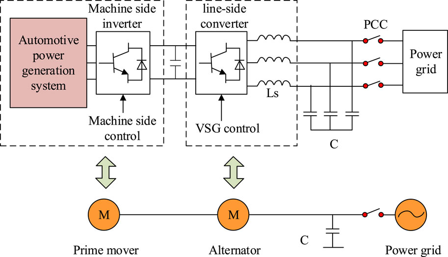
Figure 1. Structure of VSG.
The synchronous machine model in virtual synchronous machine technology can adopt different levels of simulation models. Although higher-order models theoretically have more precise accuracy, their value in practical applications is limited due to their complexity and high computational costs (Salem et al., 2023). Therefore, the experiment adopts a second-order hidden pole synchronous machine model as the core of VSG, while assuming that the model does not include the magnetic saturation effect of the iron core and rotor damping. The corresponding operational structure of the SG is Figure 2.
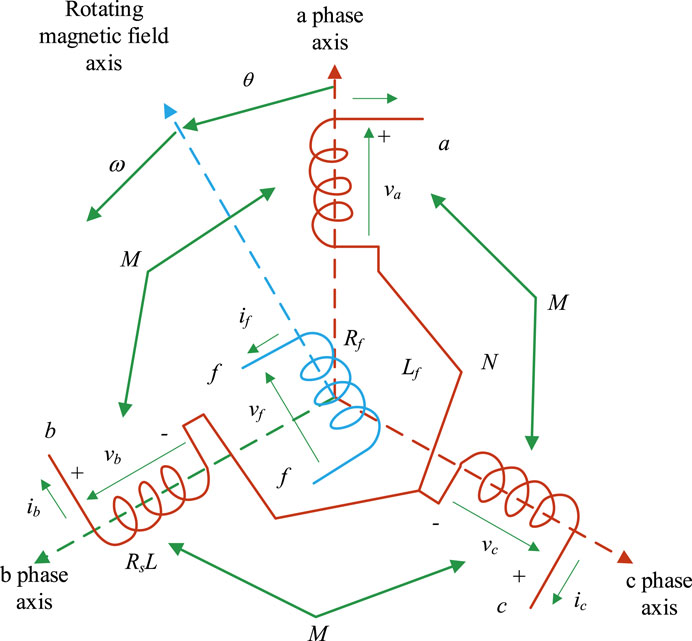
Figure 2. Operating structure of SG.
Assuming that variable DC current source
In Eq. 1,
The above equation and the principle of VSG indicate that frequency stability is a key indicator for the operation of automotive power systems. Its fluctuations not only reduce the operational efficiency of power grid equipment, but may also affect the entire system’s stability. If the frequency deviation is not corrected in a timely manner, it may seriously interfere with the normal operation of the car, and even lead to the collapse of the power grid frequency. In traditional SGs, the static characteristic equation between the AP and frequency of the generator, as well as the mechanical equation, can be established through a speed controller. The specific calculation is Eq. 3.
In Eq. 3,
In Eq. 4,
In Eq. 5,
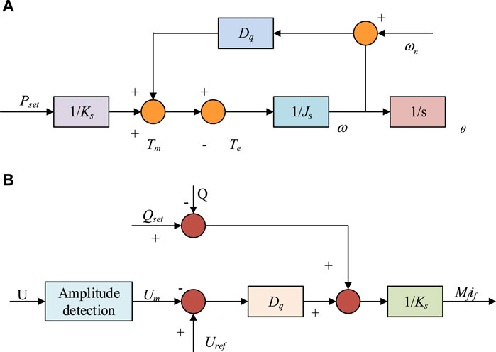
Figure 3. Flow of VSG AP control and reactive voltage control. (A) VSG active power control diagram (B) VSG reactive voltage control diagram.
In VSG design, inertia and damping are crucial for the inertial response of VSG. The larger the inertia time constant, the more difficult it is for the generator rotor to accelerate, and the corresponding natural oscillation angle frequency and damping coefficient will be smaller. The inertia time constant is usually defined based on the rated capacity of the generator and is used to obtain the dynamic response time, as shown in Eq. 6.
In Eq. 6,
3.2 IC-NEVsPG based on VSG
The suppression of frequency fluctuations at the grid connection point in this study plays a crucial role in the grid connection stability of NEVs. In islanding mode, the output voltage of NEVs will vary with the load, making it difficult to maintain a stable rated frequency. To reduce frequency fluctuations at the grid connection point, improve the dynamic response of NEVs converters, and achieve seamless frequency modulation in islanding mode, this experiment proposes to improve the VSG control strategy using LADRC. By linearizing the controller and linking various parameters in the system with the bandwidth of the controller and observer, the problem of parameter tuning is simplified (Wu et al., 2023). At the same time, the tracking differential part in ADRC is omitted, and the extended state observer (ESO) and nonlinear state error feedback (NLSEF) are linearized and transformed into Linear Extended Star Observer (LESO) and linear state error feedback (LSEF). Among them, ESO is used to observe the output of the system and estimate its existence of disturbances. NLSEF is used to receive the results of ESO observations, control system errors, and compensate for disturbances. LESO is an observer used in control systems, whose core function is to estimate the system state, especially in situations where the system state is difficult to measure directly. The design purpose of LESO is to quickly and accurately observe unknown disturbances and states in the system, and it plays an important role in active disturbance rejection control (ADRC) technology. Taking second-order LADRC as an example, its structure is shown in Figure 4.
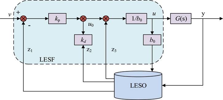
Figure 4. Second order LADRC.
When the PGS of NEVs is considered as a second-order controlled object, the differential equation
In Eq. 7,
In Eq. 8,
In Eq. 9,
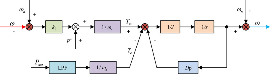
Figure 5. VSG active frequency loop control process.
In Figure 5,
In Eq. 10,
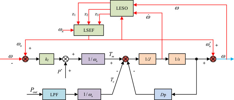
Figure 6. VSG control based on LADRC.
In summary, the transfer function of
In Eq. 11,
In Eq. 12,
Eq. 13 constrains
4 Performance testing and application effects of the IC-NEVsPG system
With the rapid growth of NEVs worldwide, the operation of their PGSs has become an undeniable topic. Especially in terms of power grid stability and energy efficiency, the control technology of NEVs PGSs is particularly important. Therefore, this experiment aims to explore the practical effects and potential advantages of improving VSG technology in NEVs through comprehensive performance testing and practical application case analysis.
4.1 Performance testing of IC-NEVsPG system
To test and analyze the proposed control strategy, a model of an AC-DC hybrid micro-grid containing electric vehicles is built using PSCAD/EMTDC software, as shown in Figure 7.
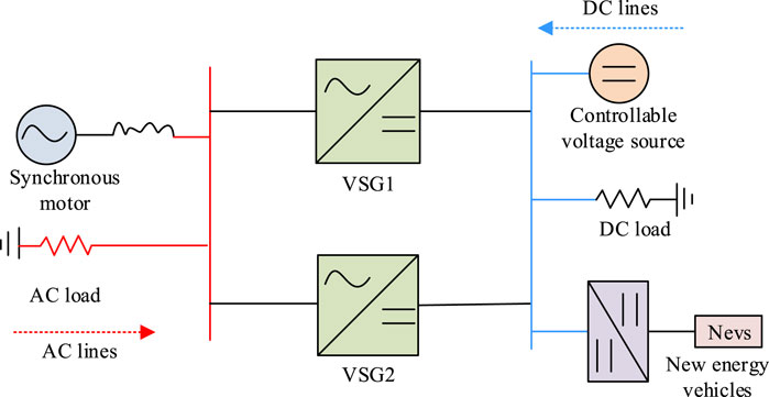
Figure 7. Testing of AC/DC hybrid power grid.
In Figure 7, in the test system, the AC power supply is equivalent to a synchronous motor, and the DC power supply is equivalent to a controllable voltage source. Energy conversion is realized on both sides of AC and DC through two VSG connections, and a certain amount of load is connected. The electric vehicle is connected to the DC bus through a bidirectional DC/DC converter. Table 1 shows the PGS parameters.
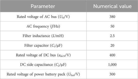
Table 1. Partial parameters of new energy generation system.
Based on the above experimental setup, ignoring the impact of NEVs access, load fluctuation testing of the PGS is started. When the time is 3s, the load of the system is suddenly increased by 10 kW. The entire process of frequency variation during system load fluctuations during this process is Figure 8.
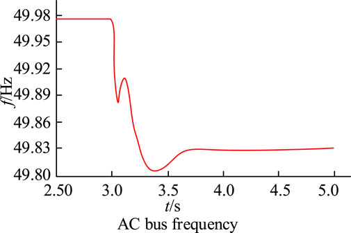
Figure 8. AC bus frequency.
The variation of the curve in Figure 8 shows that the frequency of the system begins to slowly decrease during load fluctuations, and it can overcome the shortcomings of inertia in traditional control strategies during power generation, effectively enhancing the frequency stability. Under the virtual inertial control strategy, NEVs can give voltage support for the DC power grid. This support can be controlled by adjusting the value of the virtual inertia coefficient (VIC). Different coefficients have different effects on the voltage response of the system when the load suddenly changes. When the load of 10 kW is suddenly increased for 3s, the changes in DC bus voltage (DC-BV) and NEVs power can be obtained as shown in Figure 9.
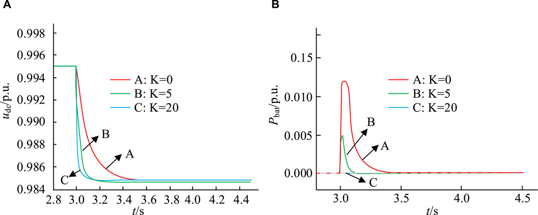
Figure 9. Changes in DC-BV and NEVs power. (A) Changes in DC bus voltage (B) Changes in the power of new energy vehicles.
The three waveforms in Figure 9A show the changes in DC-BV under the conditions of VICs of 0, 5, and 20, respectively. The three waveforms in Figure 9B represent the changes in power of NEVs. In waveform A, when the VIC is 0, under the droop control, the DC-BV will rapidly decrease when the load suddenly increases, and NEVs will hardly intervene in the regulation of the grid voltage. In waveform B, after introducing the VIC K = 5, the decrease rate of the DC-BV of NEVs slows down, indicating that NEVs will increase the power output of the grid when the load suddenly increases. Waveform C further shows that increasing the VIC can improve the output of NEVs to the grid power during sudden load increases, making the decrease rate of DC-BV slower. The above results indicate that under virtual inertial control, NEVs can effectively provide voltage support for the DC network of micro-grids. By adjusting the VIC, the degree to which NEVs participate in voltage support can be controlled. However, when the VIC exceeds a certain limit value, virtual inertia control may cause system instability, so it is necessary to choose an appropriate VIC.
To test the effectiveness of the virtual inertia control strategy, this experiment selects the DC micro-grid voltage regulation method based on fractional order virtual inertia method (VRM-DC), the electric vehicle V2G technology based on inverter and optimal non integer model virtual inertia control (OAIM-VIC), and the constructed LADRC-VSG method for load fluctuation comparison (Khooban, 2020; Long et al., 2022). The above three methods are respectively referred to as strategies A, B, and C. Similarly, when the time is 3 s, the load of the system is suddenly increased by 10 kW. When the time is 4 s, the load begins to return to normal. The obtained load test results are shown in Figure 10.
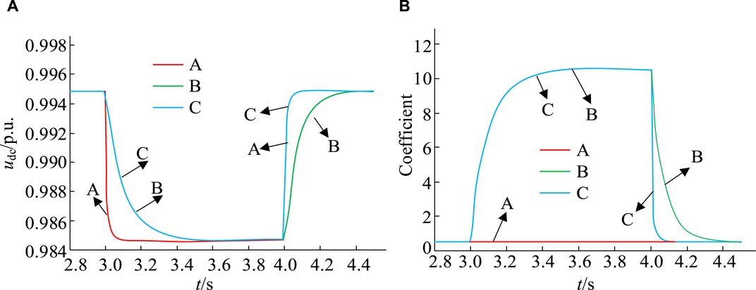
Figure 10. Changes in DC-BV and VIC. (A) Changes in DC bus voltage (B) Comparison of virtual inertia coefficient.
Figure 10A, B show the changes in DC-BV and VIC under different strategy operations. Analyzing the changes in waveform A in Figure 10, under the VRM-DC strategy, when the value of the VIC is very small or close to 0, the voltage drop rate of the DC network is faster. The inertia of DC voltage is small, and NEVs are hardly involved in voltage regulation. Under the OAIM-VIC strategy, the VIC will change according to the specific fluctuation of the grid voltage, allowing NEVs to participate in the regulation of the grid voltage. Waveform B represents the dynamic response change of the DC-BV. The speed of the decrease in DC-BV is significantly slowed down, and the stability of the voltage is significantly improved. In waveform C, the LADRC-VSG method can not only slow down voltage fluctuations, but also accelerate recovery speed and improve voltage stability. The above analysis indicates that adjusting the VIC appropriately can slow down voltage fluctuations while maintaining recovery speed, thereby enhancing the stability of the DC network.
4.2 Simulation results of grid connection modes for different virtual inertial control strategies
The correctness of the proposed NEVs power generation strategy is verified and simulated in MATLAB R2020b/Simulink environment. The experiment is carried out with a NEV as the research object, and ANOVA test is used to select the test. At the beginning of the experiment, NEVs are connected to the grid with an AP of -4kW, achieving single power factor charging. When the time reaches 0.6s, the AP setting of NEVs is adjusted to 4kW, and it is converted to discharge to the grid at a unit power factor. By monitoring the frequency fluctuations and power output changes of the grid connection points in the monitoring system, simulation results are exhibited in Figure 11.
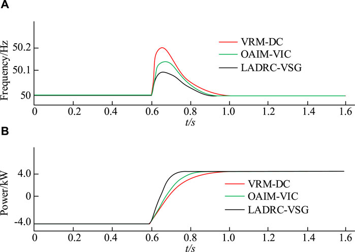
Figure 11. Frequency and AP output of grid connection points. (A) Grid connection point frequency (B) Active power output.
Figure 11A shows the frequency variation of NEVs at the grid connection point. The comparison of different VSG control strategies shows that the frequency fluctuations at the grid connection points of VRM-DC, OAIM-VIC, and LADRC-VSG are 0.18Hz, 0.14Hz, and 0.08Hz, respectively. Compared to VRM-DC and OAIM-VIC, LADRC-VSG significantly reduces the frequency of grid connection by 55% and 43%. Figure 11B shows the output variation of AP of NEVs. When given a change in AP, the dynamic process of VRM-DC’s grid connected output power lasts for 0.33 s. Under the control of OAIM-VIC and LADRC-VSG, the dynamic process of grid connected output power lasts for 0.22 s and 0.16 s, respectively. The comparison shows that the LADRC-VSG strategy has significant advantages in terms of disturbance resistance and dynamic performance. Then, under the initial conditions, the system load is set to 12kW, which means the initial given AP
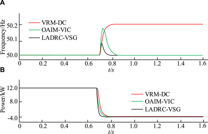
Figure 12. Simulation results in island mode. (A) VSG output frequency (B) VSG output active frequency.
Figure 12A shows the VSG output power. Under VRM-DC control, the fluctuation of system output frequency caused by load changes ultimately increases by 0.2 Hz and tends to stabilize. When using OAIM-VIC control, the frequency fluctuation increases by 0.18 Hz and then returns to the rated frequency of 50 Hz. Under LADRC-VSG, the frequency fluctuation only increases by 0.09 Hz to restore to the rated frequency of 50 Hz. In Figure 12B), after a sudden load change under three control strategies, the output AP of the system decreases from 12 kW to 4 kW. However, under LADRC-VSG, the duration of the dynamic process of system output power is the shortest, only 0.05 s. Under VRM-DC control and OAIM-VIC control, the duration is 0.1 s and 0.08 s, respectively. This indicates that the LADRC-VSG strategy performs better in terms of dynamic performance and frequency regulation ability.
Based on the above results, compared to the VRM-DC control proposed in reference (Long et al., 2022) and the OAIM-VIC control strategy proposed in reference (Khooban, 2020), the LADRC-VSG strategy has very superior performance in improving new energy electric vehicles. To emphasize the superiority of the research method, the performance results of the three methods are compared. The results are shown in Table 2.
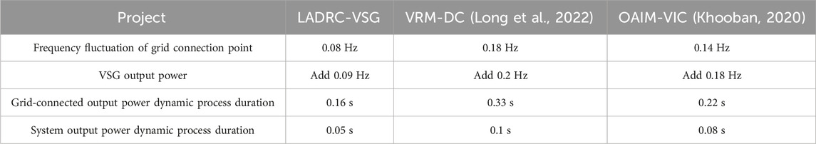
Table 2. Comparison results.
5 Conclusion
The widespread application of NEVs PGSs has led to a series of problems such as inertia loss in automotive PGSs, and has brought adverse effects on the stable operation of the system. Therefore, this study proposed an IC-NEVsPG strategy that integrates LADRC and VSG. Firstly, an analysis was conducted on the VSG strategy, followed by the improvement of VSG using LADRC technology, which was jointly applied to the inertial control of NEVs PGSs. The results showed that adjusting the VIC appropriately could control the degree to which NEVs participate in voltage support. Under the LADRC-VSG strategy, voltage fluctuations could be effectively reduced and recovery speed could be accelerated. The changes in the frequency of NEVs at the grid connection point showed that the frequency fluctuations of VRM-DC and OAIM-VIC strategies at the grid connection point were 0.18 Hz and 0.14 Hz, respectively. The frequency fluctuation of the grid connection point under LADRC-VSG operation was 0.08 Hz. In the comparison of AP, under the control of VRM-DC, OAIM-VIC, and LADRC-VSG strategies, the dynamic process of grid connected output power lasted for 0.33 s, 0.22 s, and 0.16 s, respectively. The above data all indicate that the LADRC-VSG strategy not only provides new theoretical and technical support for the effective integration of the power grid and NEVs, but also provides practical guidance for further improving the stability and reliability of smart grids. In the future, the charging and discharging of electric vehicles will become more large-scale and orderly with the construction of large-scale charging stations, the unification of electric vehicle battery standards, and the gradual adoption of battery replacement charging methods. This will enable electric vehicles to participate in the frequency and voltage regulation of the power grid. The ability will be stronger, and the proposed control strategy will be more practical and economical. However, the experiment was analyzed and tested solely through the constructed simulation model, without any physical tests being conducted. Additionally, due to time constraints and lack of experimental conditions, only the effectiveness of the improved VSG electric vehicle charge and discharge control method was verified. This experiment failed to further verify the control effect of multiple electric vehicles participating in charging and discharging.
Data availability statement
The original contributions presented in the study are included in the article/supplementary material, further inquiries can be directed to the corresponding author.
Author contributions
MD: Data curation, Writing–original draft. HM: Conceptualization, Methodology, Writing–review and editing.
Funding
The author(s) declare that no financial support was received for the research, authorship, and/or publication of this article.
Conflict of interest
HM was employed by the China Automotive Technology and Research Center Co., Ltd.
The remaining author declares that the research was conducted in the absence of any commercial or financial relationships that could be construed as a potential conflict of interest.
Publisher’s note
All claims expressed in this article are solely those of the authors and do not necessarily represent those of their affiliated organizations, or those of the publisher, the editors and the reviewers. Any product that may be evaluated in this article, or claim that may be made by its manufacturer, is not guaranteed or endorsed by the publisher.
References
Albert, J. R., Selvan, P., Sivakumar, P., and Rajalakshmi, R. (2022). An advanced electrical vehicle charging station using adaptive hybrid particle swarm optimization intended for renewable energy system for simultaneous distributions. J. Intelligent Fuzzy Syst. 43 (4), 4395–4407. doi:10.3233/jifs-220089
Chang, J., Du, Y., Lim, E. G., Wen, H., Li, X., and Jiang, L. (2021). Coordinated frequency regulation using solar forecasting based virtual inertia control for islanded microgrids. IEEE Trans. Sustain. Energy 12 (4), 2393–2403. doi:10.1109/tste.2021.3095928
Choudhuri, S., Adeniye, S., and Sen, A. (2023). Distribution alignment using complement entropy objective and adaptive consensus-based label refinement for partial domain adaptation. Artif. Intell. Appl. 1 (1), 43–51. doi:10.47852/bonviewaia2202524
Elizabeth Michael, N., Hasan, S., and Mishra, S. (2020). Virtual inertia provision through data centre and electric vehicle for ancillary services support in microgrid. IET Renew. Power Gener. 14 (18), 3792–3801. doi:10.1049/iet-rpg.2020.0217
Idan, R. F., Mahdi, A. J., and Abdul Wahhab, T. M. (2023). Review on virtual inertia control topologies for improving frequency stability of microgrid. Eng. Technol. J. 41 (2), 1–14. doi:10.30684/etj.2022.136217.1304
Jafari, H., Moghaddami, M., Olowu, T. O., Sarwat, A. I., and Mahmoudi, M. (2020). Virtual inertia-based multipower level controller for inductive electric vehicle charging systems. IEEE J. Emerg. Sel. Top. Power Electron. 9 (6), 7369–7382. doi:10.1109/jestpe.2020.3032898
Khokhar, B., Dahiya, S., and Singh Parmar, K. P. (2020). A robust cascade controller for load frequency control of a standalone microgrid incorporating electric vehicles. Electr. Power Components Syst. 48 (6-7), 711–726. doi:10.1080/15325008.2020.1797936
Khooban, M. H. (2020). An optimal non-integer model predictive virtual inertia control in inverter-based modern ac power grids-based v2g technology. IEEE Trans. Energy Convers. 36 (2), 1336–1346. doi:10.1109/tec.2020.3030655
Long, B., Zeng, W., Rodriguez, J., Guerrero, J. M., Hu, J., and Chong, K. T. (2022). Enhancement of voltage regulation capability for dc-microgrid composed by battery test system: a fractional-order virtual inertia method. IEEE Trans. Power Electron. 37 (10), 12538–12551. doi:10.1109/tpel.2022.3171556
Magdy, G., Ali, H., and Xu, D. (2021). Effective control of smart hybrid power systems: cooperation of robust LFC and virtual inertia control systems. CSEE J. Power Energy Syst. 8 (6), 1583–1593. doi:10.17775/CSEEJPES.2020.05230
Mitra, J., and Nguyen, N. (2022). Grid-scale virtual energy storage to advance renewable energy penetration. IEEE Trans. Industry Appl. 58 (6), 7952–7965. doi:10.1109/tia.2022.3202515
Muhtadi, A., Pandit, D., Nguyen, N., and Mitra, J. (2021). Distributed energy resources based microgrid: review of architecture, control, and reliability. IEEE Trans. Industry Appl. 57 (3), 2223–2235. doi:10.1109/tia.2021.3065329
Rasool, A., Yan, X., Rasool, U., Abbas, F., Numan, M., Rasool, H., et al. (2020). Enhanced control strategies of VSG for EV charging station under a low inertia microgrid. IET Power Electron. 13 (13), 2895–2904. doi:10.1049/iet-pel.2019.1592
Rathore, B., Chakrabarti, S., and Srivastava, L. (2021). ARI and ARID control of virtual synchronous generator for frequency response improvement. IET Renew. Power Gener. 15 (3), 664–675. doi:10.1049/rpg2.12054
Salem, R. B., Aimeur, E., and Hage, H. (2023). A multi-party agent for privacy preference elicitation. Artif. Intell. Appl. 1 (2), 98–105. doi:10.47852/bonviewaia2202514
Terazono, D., Liu, J., Miura, Y., Sakabe, S., Bevrani, H., and Ise, T. (2020). Grid frequency regulation support from back-to-back motor drive system with virtual-synchronous-generator-based coordinated control. IEEE Trans. Power Electron. 36 (3), 2901–2913. doi:10.1109/tpel.2020.3015806
Tinajero, M. Z., Ornelas-Tellez, F., and Garcia-Barriga, N. (2022). Optimal control of an inverter-based virtual synchronous generator with inertial response. IEEE Lat. Am. Trans. 20 (5), 780–786. doi:10.1109/tla.2022.9693562
Wu, Z., Zhao, Y., and Zhang, N. (2023). A literature survey of green and low-carbon economics using natural experiment approaches in top field journal. Green Low-Carbon Econ. 1 (1), 2–14. doi:10.47852/bonviewglce3202827
Zeng, W., Li, R., Huang, L., Liu, C., and Cai, X. (2021). Approach to inertial compensation of HVDC offshore wind farms by MMC with ultracapacitor energy storage integration. IEEE Trans. Industrial Electron. 69 (12), 12988–12998. doi:10.1109/tie.2021.3134092
Keywords: virtual synchronous generator, inertia, new energy, automobile power generation, control system, smart grid, stability
Citation: Du M and Mei H (2024) The application of virtual synchronous generator technology in inertial control of new energy vehicle power generation. Front. Mech. Eng 10:1382664. doi: 10.3389/fmech.2024.1382664
Received: 06 February 2024; Accepted: 22 March 2024;
Published: 10 April 2024.
Edited by:
Hamit Solmaz, Gazi University, TürkiyeReviewed by:
Çağdaş Hisar, Gazi University, TürkiyeImdadullah Imdadullah, Aligarh Muslim University, India
Copyright © 2024 Du and Mei. This is an open-access article distributed under the terms of the Creative Commons Attribution License (CC BY). The use, distribution or reproduction in other forums is permitted, provided the original author(s) and the copyright owner(s) are credited and that the original publication in this journal is cited, in accordance with accepted academic practice. No use, distribution or reproduction is permitted which does not comply with these terms.
*Correspondence: Hailong Mei, 13915010951@163.com