Experimental investigation of tungsten–nickel–iron alloy, W95Ni3.5Fe1.5, compared to copper monolithic bullets
 T. Abhishek1
  Dola Sundeep2*
  C. Chandrasekhara Sastry1*
  K. V. Eswaramoorthy2
  Gagan Chaitanya Kesireddy1
  Bobbili Veera Siva Reddy1
  Rakesh Kumar Verma3
  Sachin Salunkhe4,5
  Robert Cep6
  Emad Abouel Nasr7
- 1Department of Mechanical Engineering, Indian Institute of Information Technology Design and Manufacturing (IIITDM) Kurnool, Kurnool, Andhra Pradesh, India
- 2Department of Electronics and Communication Engineering, Indian Institute of Information Technology Design and Manufacturing (IIITDM) Kurnool, Kurnool, Andhra Pradesh, India
- 3Electronics and Radar Development Establishment (LRDE), Defence Research and Development Organization, Bangalore, Karnataka, India
- 4Department of Biosciences, Saveetha School of Engineering, Saveetha Institute of Medical and Technical Sciences, Chennai, India
- 5Department of Mechanical Engineering, Gazi University Faculty of Engineering, Ankara, Türkiye
- 6Department of Machining, Assembly and Engineering Metrology, Faculty of Mechanical Engineering, VSB—Technical University of Ostrava, Ostrava, Czechia
- 7Department of Industrial Engineering, College of Engineering, King Saud University, Riyadh, Saudi Arabia
Introduction: The demand for improved small arms ammunition has led to exploring advanced materials and manufacturing techniques. This research investigates the machining characteristics of CM and WNF alloy bullets, aiming to enhance ballistic performance and durability.
Methods: Bullet profile-making trials were conducted to evaluate the impact of machining parameters such as cutting speed and feed. The study also considered variables including surface roughness, cutting temperature, and hardness, alongside a detailed morphological analysis, The evaluation utilized an orthogonal array and MCDM approach, incorporating the TOPSIS method for decision-making processes.
Results: The findings reveal that WNF alloy bullets exhibit 3.01% to 27.95% lower machining temperatures, 24.88%-61.85% reduced surface roughness, and 19.45%-34% higher microhardness compared to CM bullets. Moreover, CM bullets demonstrated higher machining temperatures, resulting in 47.53% increased tool flank wear. WNF bullets showed a 24.89% reduction in crater wear and a 38.23% decrease in compressive residual stress in bullet profiles, indicating superior machining performance.
Discussion: The superior machining performance of WNF alloy bullets suggests their potential to improve the ballistic performance and durability of small arms ammunition. The reduced tool wear and favorable machining parameters highlight WNF alloy's advantages for military and defense applications. A ballistic impact analysis using a finite element method (FEM) model in Abaqus software further supports the potential of WNF alloy bullets, providing a solid foundation for future advancements in bullet manufacturing technologies.
1 Introduction
The science behind manufacturing a bullet is an essential part of ballistics operations. It plays a vital role in making, firing, ejecting, and fragmenting the bullet (Ma et al., 2004). In the defense sector, a non-standard dimension is crucial for identifying the key features that influence operation. As bullets and casings are fired or ejected from the gun barrel, definite signature characteristics are left behind in the form of striations on the bullet and along the barrel passage of the gun. The essential operation of making bullets is the casting operation (Banerjee et al., 2022), where the molten metal is poured in a cope and drag operation and then further subjected to machining cycles. It found wide applications in making pointed, cylindrical, and cylindro-conical profiles (Li et al., 2022). These have been made into various sizes, and testing has been carried out for both standard and non-standard dimensions to decrease the roughness factor. Augmenting the hardness factor was found to be the primary requirement for a bullet profile. To ensure they meet the standards, ball grooves were provided, and highly homogeneous alloys were considered as alternatives to copper (Banerjee et al., 2022; Li et al., 2022), increasing the efficiency and reducing air resistance significantly. However, even new alloy materials caused the bullet to drift from its trajectory to the intended target, as decreased weight leads to accuracy deviations (Ma et al., 2004; Banerjee et al., 2022; Li et al., 2022).
The essential design criteria of bullets should address and solve two primary problems. In the gun barrel, they should form a complete seal in the gun bore, as a weak seal would cause a leakage in the propellant area of charge, thereby decreasing the accuracy and efficiency of the intended operation. Excess friction between the gun barrel and bullet must be reduced (Sastry et al., 2019a). These form the core of internal ballistics, ensuring bullets are produced to high standards with minimal surface imperfections, improving accuracy. An array of bullet molds with various design profiles and calibers are available from manufacturers such as RCBS, PJ, and DM. With these specialized molds, bullets can be made on an as-needed basis, based on the time- and cost-effective material. Although bullets can be cast in various shapes and sizes, the bulk of the material is removed through a diamond turning operation (Sastry et al., 2019a; Sastry et al., 2019b), which must be a controlled cycle operation. Both cast and jacketed bullets are available commercially, but casting and removing bulk material as scrap is convenient for testing non-standard dimensions (Sastry et al., 2019b). As a reference standard for ballistic identification, the actual bullet signature in terms of shape, size, material, and color of all physical standard bullets is identified and duplicated when testing the method and surface attributes of the bullets (Ma et al., 2004; Sastry et al., 2019a; Sastry et al., 2019b; Banerjee et al., 2022; Li et al., 2022).
The environment of the machining operation can be divided into dry and wet machining conditions. The presence of cutting fluids increases chip removal, decreases friction, and causes a drop in temperature. However, it also leads to a harmful user environment, which causes severe, irreversible problems for machining operators (Sastry et al., 2019b). The change in surface attributes is also observed for soluble-oil mixed coolants, which are generally used for all machining conditions. However, a drastic change is observed in the surface properties and roughness, which is a significant drawback of the functional coolants used in the machining cycle (Sastry et al., 2020a). In the present day, dry machining is used as it ensures the surface attributes of the workpiece material remain unchanged (Thirumavalavan et al., 2019; Sastry et al., 2020b; Hariharan et al., 2020; Rajamanickam et al., 2020; Selvakumar et al., 2020).
Much work has been carried out in dry machining conditions for the defense and aerospace sectors owing to the retention of surface chemical and physical properties, which are also classified as green machining (cleaner production) (Sastry et al., 2020b). For most of their work, scientists and researchers have analyzed machining operations using optimal cutting parameters, factors, and their equivalent responses using the Taguchi orthogonal array method (Navukkarasan et al., 2020). Though an orthogonal array provides a wide-based solution, it has its fair share of drawbacks as it is a single-response variable analysis of the responses to the factors (Sastry et al., 2020b; Navukkarasan et al., 2020). The method does not create a vertical plane to consider all the factors equally and mixed attributes are not taken into full consideration for detailed machining operations (Gopinath et al., 2021; Pradeep et al., 2021; Praveen Raj Navukkarasan et al., 2021). The multi-criteria decision-making process ensures all the factors and responses based on the weighted criteria are considered in an equal vector plane (Praveen Raj Navukkarasan et al., 2021). Researchers have adopted Artificial Neural Networks (ANN), Analytic Hierarchy Process (AHP), Grey System Theory (GREY), Technique for Order Preference by Similarity to Ideal Solution (TOPSIS), Particle Swarm Optimization (PSA), and Elimination and Choice Translating Reality (ELECTRE) techniques to develop common objectives for identifying the best input factors correlated to the measured responses. The drawbacks of these optimization techniques compared to the technique for preference by similarity to ideal solution (TOPSIS) are high iterations and complex algorithms, as TOPSIS uses simple elementary weighted operations to provide a close-to-ideal solution (Sastry et al., 2019a; Sastry et al., 2019b; Gopinath et al., 2021; Praveen Raj Navukkarasan et al., 2021).
To the authors’ knowledge, no work has yet compared machining and making bullet profiles with tungsten–nickel–iron alloy, W95Ni3.5Fe1.5 (WNF) to copper monolithic (CM) bullets. The factors considered for the machining operation of the bullet profile are cutting speed and feed, and analogous responses are surface roughness, cutting temperature, and hardness. A detailed morphological study is done for the workpieces, chips, and tools used for bullet making, as indicated in Supplementary Figure S1. Residual stress analyses are carried out for WNF and copper monolithic (CM) bullets to study the changes in surface attributes. A complete simulation model is also considered, thereby adapting the work to a real-time environment.
2 Materials and methods
2.1 Workpiece for machining the bullet profile
The workpieces in this experiment are tungsten–nickel–iron alloy W95Ni3.5Fe1.5 and copper monolithic bullets whose dimensions are ɸ13.1 mm in diameter and 25 mm in length. The workpiece used is described in Supplementary Figures S2A, B. The physical and chemical properties of the tungsten–nickel–iron alloy W95Ni3.5Fe1.5 and copper monolithic bullets are listed in Supplementary Tables S1, S2, respectively.
2.2 Machine: CNC lathe specifications
Hardinge designed and built series turning centers for making bullet profiles close to tolerance limits, as indicated in Supplementary Figures S2C–F. The computer numerical control (CNC) lathe machine in the Central Institute of Tool Design (CITD), MSME Tool Room, Government of India, Hyderabad, was used to machine the bullet profiles. The machine specifications are highlighted in Supplementary Table S3. The A2-5 spindle nose, with a horsepower of 15 kW and high spindle speeds, allowed wide trial variations before finalizing the factor variables. The machining was carried out using an A4SM short-projection Kennametal tool, which is depicted in Supplementary Figures S2G–I. The insert used for machining is a titanium aluminum nitride-coated tool, as bullet profile-making requires high hardness and a stable tool holder for the given dimension of the workpiece. The design data of the workpiece for the bullet module are depicted in CAD, and drawing images are depicted in Supplementary Figures S2J, K. The bullet profile machined for the WNF and CM bullets is depicted in Supplementary Figures S2L, M.
2.3 Dry machining—environment
Dry machining is classified as a clean manufacturing technique. In dry machining, the components used for material cutting, the tool, and the parameters are evaluated carefully before the operation begins (Sastry et al., 2019a). As dry machining involves high friction, a coated tool makes a vast difference in curtailing friction (Sastry et al., 2019b). Although dry machining is classified as green and clean-environment machining, its significant disadvantage lies in the tangling of chips generated in the tooltip, affecting the cutting zone area and creating a poor surface finish (Sastry et al., 2020a) and excess temperature, which induces wear (Praveen Raj Navukkarasan et al., 2021). Considering these two aspects, the cutting process and its associated parameters should be optimized for the specific machining and workpiece material conditions.
2.4 Orthogonal array experiment
Taguchi’s design technique was adopted to condense the number of required iterations. The orthogonal array set of Taguchi is widely adopted for many manufacturing/machining problems (Sastry et al., 2019a), as it efficiently classifies and identifies the factors and responses as independent planes (Sastry et al., 2019b). Furthermore, reducing the number of experiments reduces the cost and time of analyzing all the experiment runs. With the addition of signal-to-noise (S/N) ratio, the individual traits of the factors are well established in this design (Sastry et al., 2020a). For machining bullets for defense applications, the responses are cutting temperature (Tc), surface roughness (Ra), and hardness (VHN). The nose radius and depth are kept constant based on the machining profile. The factors and responses are showcased in Supplementary Table S4. The orthogonal array with factors and responses for dry machining of WNF and CM bullets is tabulated in Supplementary Table S5.
Supplementary Table S5 shows that WNF material’s temperature and surface roughness decrease and hardness increases in each of the experimental conditions compared to CM machining conditions. To ensure a common vector space that will bring in all the responses and factors in one vector plane is obtained, a multi-criteria method is used to obtain conditions close to ideal for machining the bullet profile.
2.5 Multi-criteria decision-making: TOPSIS
Step 1. The TOPSIS method is considered the ideal mechanism for appropriately culling the alternatives as it works toward a normalized value. Simo’s weighting procedure is used to allocate the rank of each output response, tabulated in Supplementary Table S6.
Supplementary Tables S7, S8 use the following equation to develop the normalized performance matrix (rij):
where i = number of alternatives (experimental runs), j = number of criteria (output responses), and xij = normalized value of the ith experimental run associated with the jth output response.
Step 2. The product of the normalized value merges the weighted normalized matrix (ϑij) into the weighted values:
The weighted matrixes are highlighted in Supplementary Tables S7, S8 for dry machining of WNF and CM tubes.
Step 3. Every option that is an ideal alternative to the best alternative performance (
where S+ delineates a decisive (positive) ideal solution, tabulated in Supplementary Table S9.
Step 4. In this progression, the execution of the criteria has been estimated as the best elective separation (D+ij) from the S+ solutions and the worst elective separation (D−ij) from the S− values. The D+ij and D−ij values are resolved utilizing the accompanying condition. Supplementary Table S11 shows the attainment of each alternative under the ideal and unfavorable conditions in dry machining conditions for CM and WNF.
where i = 1, 2, 3 ….27.
Step 5. The closeness coefficient (Ci) values are obtained for each alternative using the accompanying equation
The ideal alternative is conscripted according to the preference rank-ordered by the Ci value, which is very important to the ideal solution, as highlighted in Supplementary Table S11. The respective input values are tabulated in Supplementary Table S12. After the machining operation, the close-to-ideal solution is evaluated. Supplementary Table S12 is further sectioned based on the characterization requirement by using the wire-EDM facility for microstructure, surface morphology, chip study, and residual stress analyses. The samples are cleaned, polished, and etched to clearly depict the surface after machining in dry conditions to ensure no undue chips are present during inspection. The tool wear was analyzed to understand the effect of the machining conditions. X-ray diffraction (XRD) using a central XRD facility was done to understand the compressive stress on the machined surface for the CM and WNF material.
3 Results and discussion
3.1 Taguchi and ANOVA
The Taguchi method was adopted for the repetitive processes with a smaller, better signal-to-noise ratio. The graphic and its respective values are tabulated in Tables 1, 2.
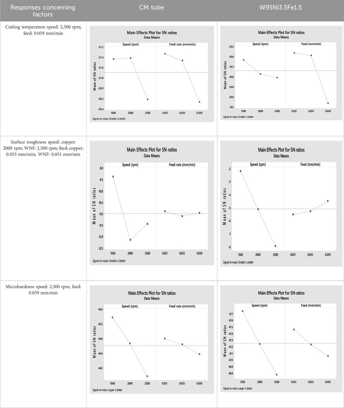
Table 1. Chemical composition and physical attributes of the W95Ni3.5Fe1.5 alloy.
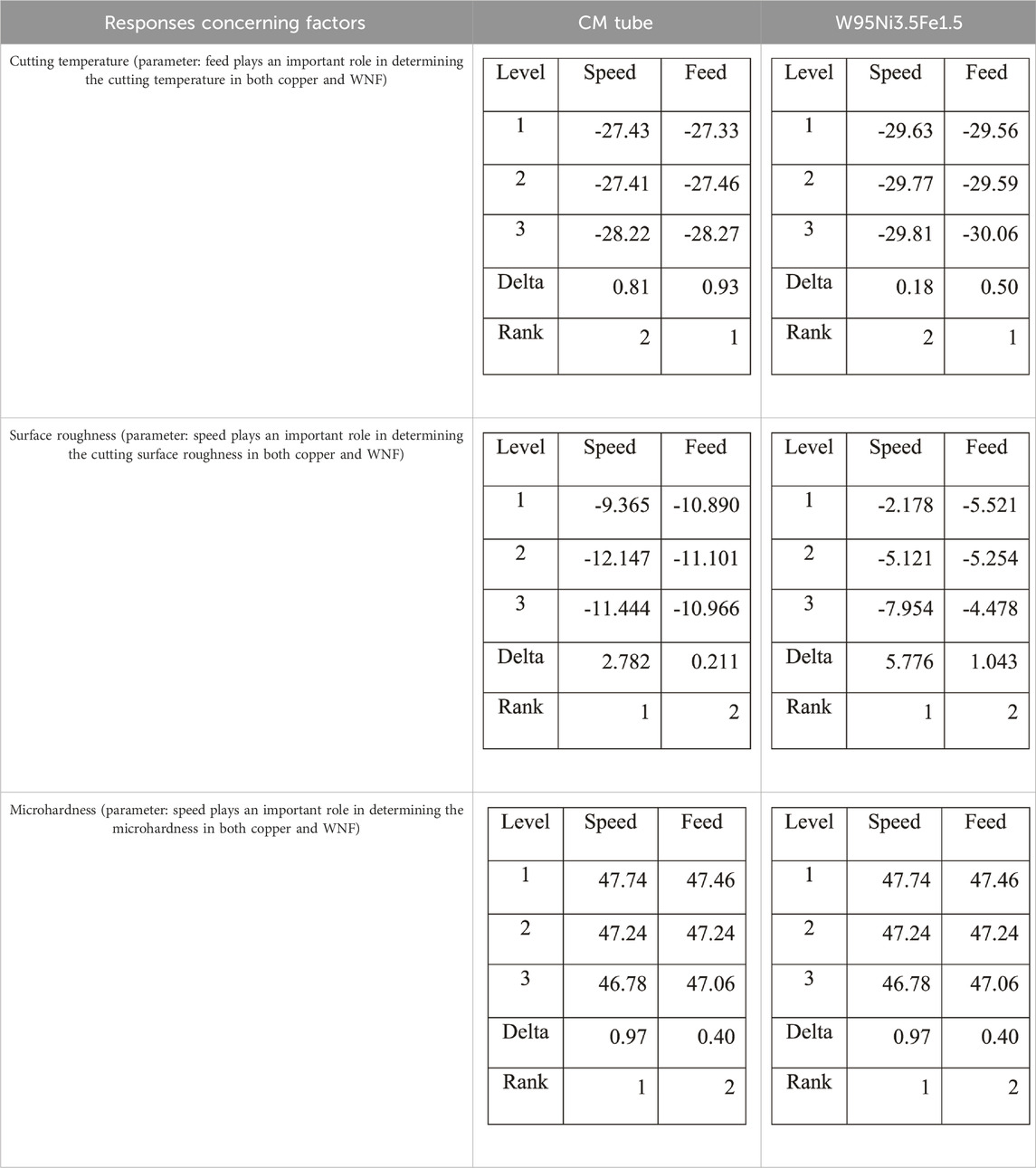
Table 2. Chemical composition and physical attributes of the CM and WNF bullets.
Analysis results of speed and feed concerning cutting temperature, surface roughness, and microhardness for dry machining conditions at a significance level of 0.05 (confidence level of 95%) are tabulated in Tables 3, 4 for CM and WNF, respectively. The rate commitment of each factor determined from analysis of variance (ANOVA) was utilized as the measure for determining the impact of each factor.
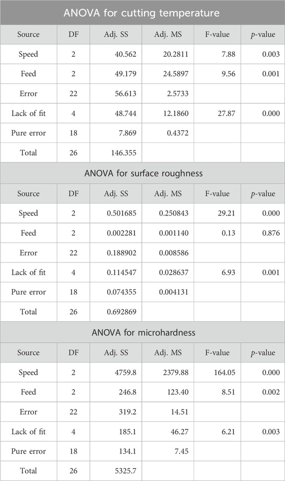
Table 3. ANOVA for dry machining of CM bullets.
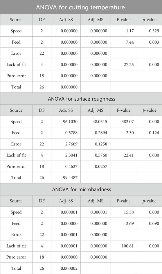
Table 4. ANOVA for dry machining of W95Ni3.5Fe1.5; ANOVA for cutting temperature.
From Tables 1, 2, applying the Taguchi method, the smaller and more significant the signal-to-noise ratio, the better. For ideal cutting temperature and microhardness, a speed of 2,500 rpm and a feed of 0.059 mm/min are the ideal cutting parameters for dry machining conditions. A speed of 2,000 rpm and a feed of 0.055 mm/min and a speed of 2,500 rpm and a feed of 0.059 mm/min are the ideal cutting parameters for surface roughness for CM and WNF, respectively, with significance given toward a smaller signal-to-noise ratio. From ANOVA (Tables 3, 4), it is found that feed plays a prominent role in determining the cutting temperature in dry machining. Meanwhile, speed plays an important role in determining surface roughness and microhardness.
3.2 Ramification of responses: temperature, surface roughness, and hardness
From the graphical data represented in Figure 1, the WNF shows 3.01%–27.95% lower machining temperatures, 24.88%–61.85% increased surface roughness, and 9.45%–34% increased microhardness values than the CM material, as indicated in Supplementary Table S13 (Sastry et al., 2019a).
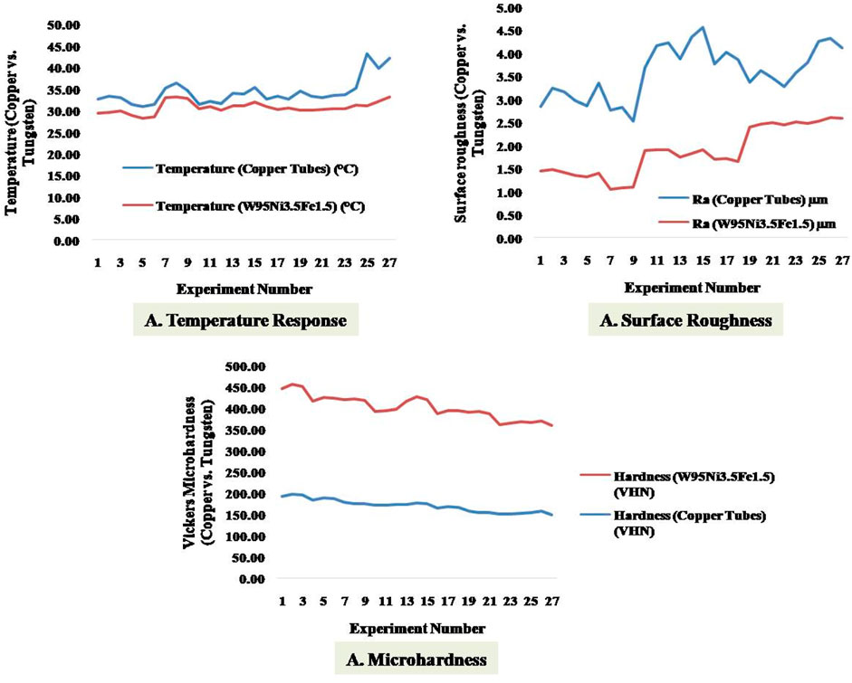
Figure 1. Comparison of temperature, surface roughness, and microhardness for copper and tungsten alloy compared to experimental order.
The temperature is attributed to the material’s density factor and softness (Sastry et al., 2019a). The WNF bullet profile density is lower than the CM bullet, which aids in the machining condition with the presence of a lower number of inclusions (Chandrasekhara Sastry et al., 2021; Praveen Raj Navukkarasan et al., 2021; Bairapudi et al., 2022; Pradeep et al., 2022; Su et al., 2022; Sundeep et al., 2022). Additionally, the minimal presence of sulfur, a consequence of delicate grain structures, and the uniform secondary distribution of particles aid in machinability at lower temperatures for WNF profiles. With a high presence, copper material increases temperatures drastically due to the attenuation in cutting forces experienced during machining (Sastry et al., 2020a). The addition of a small percentage of tin compensates for this increase, but a small addition would not form the β′ phase as that would increase hardness, leading to the formation of a duplex and thereby causing a decrease in cutting temperature (Sastry et al., 2020a; Sastry et al., 2020b). An increase in cutting temperature, as with an increase in speed values, has an overall effect on the increased surface roughness of the machined bullet profile, as is witnessed in the case of the CM bullet profile, which is a determinant factor (Evans and Bryan, 1999; Sastry et al., 2020a). The cutting temperature in the machining zone is essential as it directly affects surface roughness and microhardness properties (Sastry et al., 2019a; Sastry et al., 2019b; Rajamanickam et al., 2020). Because copper is soft and has several stress inducers, it increases the temperature during machining, causing drastic material surface changes, as depicted in the morphology section. The presence of stress inducers and many inclusions leads to the presence of coarse grains that substantially increase the temperature. This temperature increase has a profound effect on the machining zone, as the tool, which is a rigid material, will impart a higher cutting force on the softer copper material, thereby increasing the tensile residual stress in the material (Sastry et al., 2019b). The CM bullet profile has a lower microhardness value owing to its inherent softness, which is a significant drawback compared to the WNF material. With further machining at higher speeds, high tensile stresses are applied due to the augmented temperature of machining and disoriented surge in surface roughness (waviness pattern); a decrease in the microhardness value is observed, as indicated in the CM bullet profile (Sastry et al., 2020a). A detailed analysis of the tool wear and workpiece surface morphology is required to understand the ramifications of the responses to the bullet machining factors.
3.3 Ramifications of tool wear
A temperature increase in the machining zone when making the bullet profile significantly affects the cutting tool (Sastry et al., 2019b; Sastry et al., 2020a). Cutting temperature increases with increased cutting speed and feed and affects the workpiece material and the tool.
The tool life is diminished by micro-voids in the surface of the CM alloy, which can be seen during the machining cycle. The zinc combines with sulfur compounds to form zinc sulfide inclusions. These inclusions cause the formation of micro-holes in the surface. The presence of tin and nickel increases the hardness of the surface. However, due to its inherent softness, forming a built-up edge is unavoidable (Sastry et al., 2019b), causing flank wear, which increased by 47.53% in CM compared to WNF, as indicated in Supplementary Table S14. Substantial flank wear is witnessed in the case of copper alloy, as indicated in Figure 2, and a waviness pattern develops in and around the region of the machining zone. Generally, crater wear conditions are ascertained due to chemical attack or interaction during the machining operation. Crater wear is not witnessed when making WNF bullets. However, in the case of CM tubes, a significant amount of deterioration on the surface is witnessed in the tool area around the crater regions indicated in Figure 2B (Sastry et al., 2019a). The chemical reaction between sulfides and inclusions induces this. The crater and flank wear is also attributed to the increase in abrasion, as the CM material’s softness causes attenuation in surface roughness and an increase in cutting force due to the presence of inclusions. The nickel in the WNF acts as a self-lubricant, which causes a decrease in temperature during bullet making (Sastry et al., 2019b). The crater wear component is abated by 24.89% in the WNF compared to the CM owing to its lower cutting temperatures and nickel acting as a lubricant (Sastry et al., 2020a).
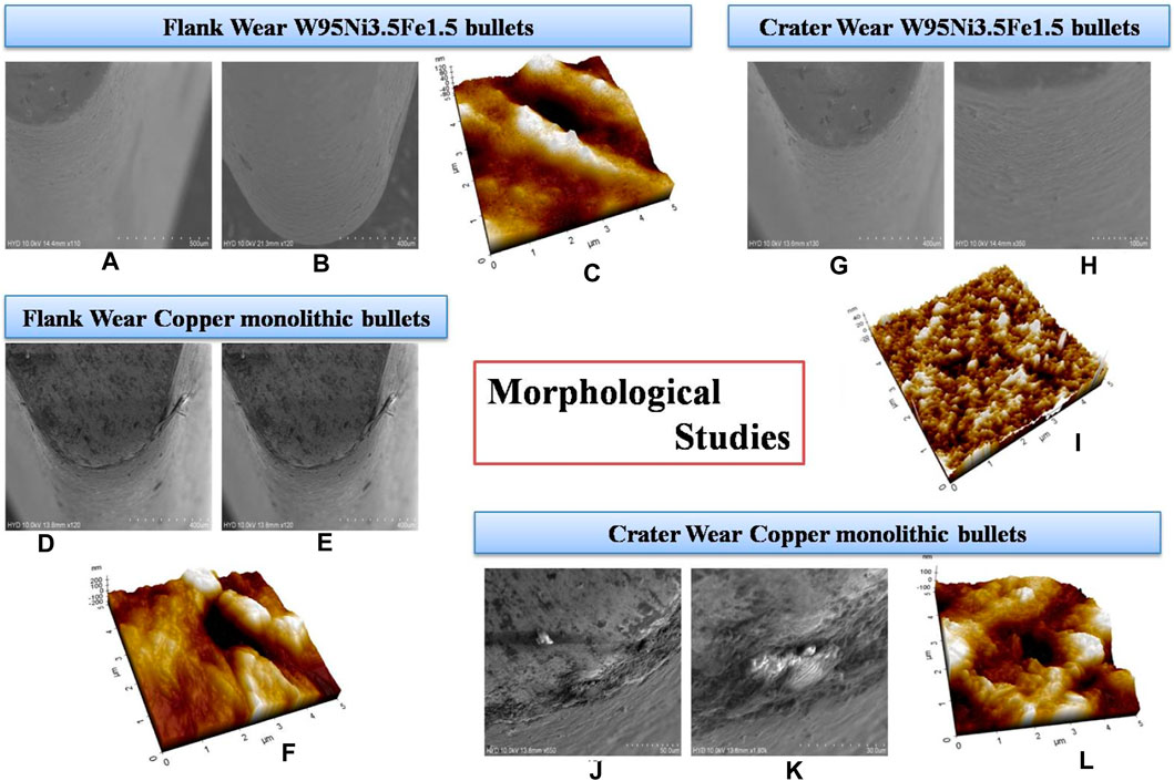
Figure 2. Crater and flank wear of W95Ni3.5Fe1.5 and CM bullets. (A, B, D, E) show the side profile of flank wear of tool used for WNF and CM bullet; (G-I, K) show the crater wear of WNF and CM bullet; (C, I, F, L) are AFM 3D wear morphological patterns of flank and crater wear of CM and WNF and CM work tool.
3.4 Surface morphology study
During bullet making, the chip slides over the tool-rake surface. The quality of the surface is important because an unsmooth surface causes friction in the firing nozzle, which nullifies the attributes of an ideal bullet profile (Chandrasekhara Sastry et al., 2021; Praveen Raj Navukkarasan et al., 2021; Bairapudi et al., 2022; Pradeep et al., 2022; Sundeep et al., 2022). A chip may be formed along the surface curls and exits along the rake face. The workpiece residual stress in the sub-surface plays a vital role in determining the solid-phase removal during bullet profile-making (Su et al., 2022). The friction coefficient witnessed in the WNF is higher than that in the CM material, owing to its high hardness and self-lubricating properties. Because less heat is generated at the tool–chip interface, fewer craters and micro-holes are observed in Figure 3 for WNF.
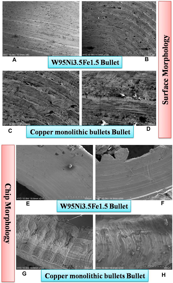
Figure 3. (A, B, E, F) surface morphology of WNF and CM bullets; and (E, F, G, H) are chip morphology of WNF and CM bullets.
3.5 Residual stress analysis
With an increase in hardness value and temperature ascertained during the making of the bullet profile in the area of the tool–chip–workpiece interface, stress is induced on the sub-layers of the workpiece. This stress is in the form of tensile/compressive factors Sastry et al., 2020b; Jhansi et al., 2023; Umadevi et al., 2023. With an increase in temperature owing to the hardness of the workpiece, the tool wear increases, risking failure during the machining cycle (Navukkarasan et al., 2020). The integrity of the surface is also affected by the effect of localized temperature, which augments the presence of residual tensile stress (Gopinath et al., 2021; Praveen Raj Navukkarasan et al., 2021). The amount of residual stress must be calculated, as it determines the surface integrity of surface and sub-surface characteristics that determine the application of the bullet (Chandrasekhara Sastry et al., 2021; Sundeep et al., 2022). For bullet profiles designed to pierce armor shields, concrete blocks, and other objects, it is essential to assess the residual factor on the surface of the workpiece. A central XRD facility was used, and a simultaneous sin2ψ method was used to calculate the residual stress factor in the sub-surface of the workpiece, as indicated in Supplementary Table S15 (Figure 4).
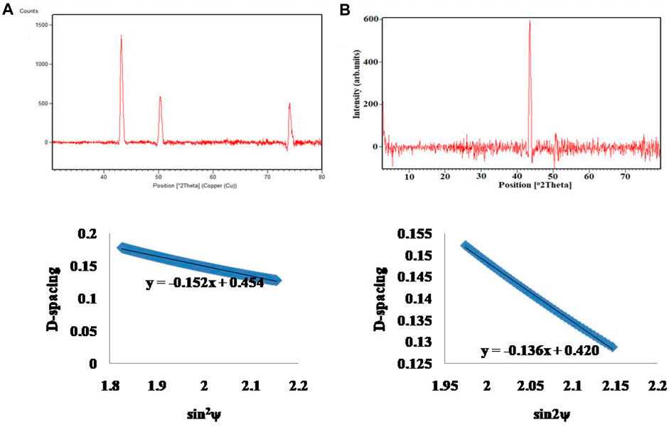
Figure 4. XRD graph plotting for (A) W95Ni3.5Fe1.5 and (B) CM bullets.
Supplementary Table S15 shows a compressive residual stress attenuation of 38.23% in the WNF bullet profile compared to the CM material. From the slope of the curve shown in Figure 4 and the calculation of the same using the sin2ψ method, it is observed that the induced stress is compressive (Praveen Raj Navukkarasan et al., 2021). Additionally, the increase in width of the XRD plot indicates that the stress factor has increased in the compressive factor in the case of the WNF bullet compared to CM material (Chandrasekhara Sastry et al., 2021). The tool life is increased as tensile stress is reduced, as indicated in Figure 2, as the temperature of machining is lower in the WNF than in the CM, causing less tensile stress in the machining zone. Furthermore, the nickel that is the primary alloying element in the tungsten alloy has high hardness and, aided by the presence of chromium, leads to a fine grain size in the machining region. The average grain size of WNF is 53 µm compared to CM grains at 92 μm, which aids in pinning the austenite grain boundaries observed when making tungsten alloy (Bairapudi et al., 2022; Pradeep et al., 2022; Sundeep et al., 2022). Fine grain will induce higher microhardness and thereby increase the factor of stress (compressive factor), as it will not allow load or applied stress from an external part to go through subsequent layers of the bullet profile. With the decreased hardness of the CM material, owing to its soft nature and coarse structure, the compressive factor is minimal, and this causes the strength of the bullet profile to be susceptible to substantial friction in real time. The minimal peak width indicates a higher dislocation density owing to a higher tensile residual stress factor and an increase in microstrain in the material due to the machining cycle (Evans and Bryan, 1999; Su et al., 2022). When making bullet profiles or test pieces for piercing, high impact resistance, secondary aging/heat treatment conditions, or alternative grades of copper should be used to induce the characteristics required for the operation.
3.6 Finite element analysis
The increase in gun culture, such as through unlicensed arms sales across the globe, hinders public and premises’ security. This opens a wide range of research on the development of sophisticated arms that are easy to handle, have less mass, have high thrust velocity, and have high bullet penetration (Jena et al., 2019). This motivated us to analyze the performance of the two fabricated pistol bullets in terms of penetration into aluminum targets of different thicknesses. The bullet dynamics at the contact point of the aluminum target plate are analyzed using finite element analysis (FEM). The study considered the size, velocity, and angular velocity of the fabricated CM and WNF bullets. The angle of impact was 0° to obtain maximum velocity and achieve maximum penetration through the target. The FEM analysis considers the detailed geometry and a relevant CAD model of a bullet with dimensions of 25 mm × 13.1 mm, as shown in Supplementary Figure S2K, for the CM and WNF bullets. The two aluminum targets are 100 × 100 × 3 mm and 100 × 100 × 9 mm cuboids with a density of 2.7 g/cc, Young’s modulus of 70 GPa, and Poisson’s ratio of 0.33, as shown in Supplementary Table S16. The properties of the CM and WNF bullet are mentioned in Tables 1, 2. The masses of the bullets were 119.1 g and 146.5 g, respectively, for the CM and WNF bullets. The non-linear dynamic ballistic impact analysis was performed on Abaqus software.
The target is fixed in Lancaster (U1 = U2 = U3 = R1 = R2 = R3 = 0), and the bullet’s velocity has assigned a muzzle velocity of 350 m/s in all the cases with a period of 100 µs. The analyses of both the bullets are instituted from the contact point of the target as shown in Figures 5A, G and Figures 5D, I for the CM and WNF bullets to nullify the deceleration of air friction. The 2D quad and 3D hexahedral meshing are used for the bullet and the aluminum target plates, respectively. Although free mesh increases the number of components and computational cost, the differences in constraints between models that use a 2D triangle or 3D tetrahedral elements are proportionally more minor. As stated above, using 2D quad or 3D hexahedral elements can help reduce element use, solution precision, and computational time (Kumar et al., 2017). Figures 5B, E, J show the penetration point of both CM and WNF bullets through the 3-mm and 9-mm aluminum targets. Both the bullets penetrated through the 3-mm aluminum target, as seen in Figures 5G, E, with a difference in time as indicated during penetration. The CM bullet penetrated the 3-mm aluminum target at 75 µs and traveled a distance of 27.58 mm from the initial point. A penetration time of 75 µs with a low traveling distance of 24.33 mm is observed in the WNF bullet. Because both bullets penetrated the 3-mm targets, the thickness of the target was increased to 9 mm to observe the failure. Figures 5H, J show the impact analysis of both bullets through the 9-mm aluminum targets. From Figure 5H, we can observe the penetration failure of the CM bullet, which deformed the target plate of 28.73 mm without completing the path of the target. The WNF bullet has penetrated through the 9-mm target with a penetration time of 50 µs and a traveled distance of 16.33 mm through the target, as shown in Figures 5K. Figures 5C, F show the final position of the CM and WNF bullets through the 3-mm aluminum target, and Figure 5K shows the final position of the WNF bullet at 100 µs. The CM and WNF bullets traveled a distance of 30.21 mm and 29.42 mm, respectively, through the 3-mm target and 28.73 mm and 31.01 mm, respectively, in the 9-mm aluminum target. All the details regarding the material, size, and properties considered for the analysis are tabulated in Table 5. Based on the above simulation, the optimum results were achieved from the WNF bullet over conventional copper bullets, which can penetrate a 9-mm aluminum target. Designing a short-range bullet with this novel WNF material can improve the penetration capacity. A real-time ballistic impact analysis can be performed with these novel bullet materials to further study the firing range of these bullets.
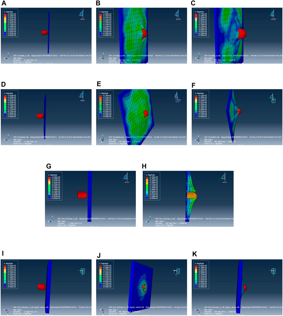
Figure 5. (A, G) and (D, I) Initial position of CM and W95Ni3.5Fe1.5 bullets when fired at the 3-mm aluminum target with a velocity of 350 m/s, (B, E, J) penetrating points of CM and WNF at 3mm and 9mm aluminum targets, (C, F) final position of CM and WNF bullets through 3mm aluminum target, (G, E) time difference in course of penetration of bullets, (H, K) impact and failure analysis of both bullets.
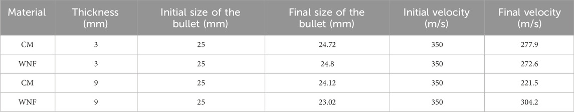
Table 5. Comparison of bullet deformation before and after penetrating the target.
4 Conclusion
The study investigates the machining of bullet profiles for defense sector applications, presenting significant findings derived from various analyses.
• Optimal cutting parameters for dry machining conditions were identified using the Taguchi method, improving cutting temperature, surface roughness, and microhardness.
• ANOVA indicated significant effects of feed and speed on machining responses, with optimal parameter combinations identified for superior performance via the TOPSIS statistical tool.
• WNF outperformed the CM material, showing lower machining temperatures, surface roughness, and higher microhardness due to its density and composition, enhancing tool wear and surface integrity.
• Tool wear mechanisms varied significantly between materials; copper’s softness increased flank wear and surface deterioration, while nickel in the alloy acted as a lubricant, reducing wear and improving surface finish.
• FEM confirmed the superior ballistic performance of WNF bullets, particularly in penetration capability, making the WNF material preferable for short-range arms fabrication.
• The study highlighted the crucial role of material selection and machining parameters in optimizing bullet performance for defense applications, offering insights for improving machining processes and bullet design effectiveness.
Data availability statement
The original contributions presented in the study are included in the article/Supplementary material; further inquiries can be directed to the corresponding authors.
Author contributions
TA: Conceptualization, Formal Analysis, Investigation, Methodology, Writing–original draft. DS: Conceptualization, Data curation, Formal Analysis, Funding acquisition, Investigation, Methodology, Project administration, Resources, Software, Supervision, Validation, Visualization, Writing–original draft, Writing–review and editing. CC: Conceptualization, Data curation, Formal Analysis, Funding acquisition, Investigation, Methodology, Project administration, Resources, Software, Supervision, Validation, Visualization, Writing–original draft, Writing–review and editing. KE: Conceptualization, Data curation, Formal Analysis, Funding acquisition, Investigation, Methodology, Project administration, Resources, Software, Supervision, Validation, Visualization, Writing–original draft, Writing–review and editing. GK: Conceptualization, Data curation, Formal Analysis, Funding acquisition, Investigation, Methodology, Project administration, Resources, Software, Supervision, Validation, Visualization, Writing–original draft. BS: Conceptualization, Data curation, Formal Analysis, Funding acquisition, Investigation, Methodology, Project administration, Resources, Software, Supervision, Validation, Visualization, Writing–original draft, Writing–review and editing. RV: Conceptualization, Data curation, Formal Analysis, Funding acquisition, Investigation, Methodology, Project administration, Resources, Software, Supervision, Validation, Visualization, Writing–original draft, Writing–review and editing. SS: Funding acquisition, Project administration, Resources, Software, Supervision, Writing–original draft. RC: Formal Analysis, Funding acquisition, Investigation, Methodology, Writing–review and editing. EA: Supervision, Validation, Visualization, Writing–review and editing.
Funding
The author(s) declare financial support was received for the research, authorship, and/or publication of this article. The authors extend their appreciation to King Saud University for funding this work through Researchers Supporting Project number (RSP2024R164), King Saud University, Riyadh, Saudi Arabia.
Acknowledgments
The authors acknowledge the Director, Department of Mechanical Engineering and Department of Electronics and Communication Engineering, Indian Institute of Information Technology Design and Manufacturing Kurnool, for providing the laboratory to perform the experiments. The authors also thank the Defence Research and Development Organisation (DRDO) laboratories for providing facilities to conduct tests and materials for conducting the experiments.
Conflict of interest
The authors declare that the research was conducted in the absence of any commercial or financial relationships that could be construed as a potential conflict of interest.
Publisher’s note
All claims expressed in this article are solely those of the authors and do not necessarily represent those of their affiliated organizations, or those of the publisher, the editors, and the reviewers. Any product that may be evaluated in this article, or claim that may be made by its manufacturer, is not guaranteed or endorsed by the publisher.
Supplementary material
The Supplementary Material for this article can be found online at: https://www.frontiersin.org/articles/10.3389/fmech.2024.1383341/full#supplementary-material
References
Bairapudi, A., Chandrasekhara Sastry, C., and Verma, C. (2022). Experimental analysis of 3D printed pallet model through fused deposition modeling. Surf. Rev. Lett. 29 (05), 2250065. doi:10.1142/s0218625x22500652
Banerjee, B., Mondal, K., Adhikary, S., Paul, S. N., Pramanik, S., and Chatterjee, S. (2022). Optimization of process parameters in ultrasonic machining using integrated AHP-TOPSIS method. Mater. Today Proc. 62, 2857–2864. doi:10.1016/j.matpr.2022.02.419
Chandrasekhara Sastry, C., Pradeep, N., Shaik, A. M., Rahman, H. A., and Patil, S. (2021). Experimental investigation of electrodeposited Ni-Al2O3/ZrO2 nanocomposite on HSLA ASTM A860 alloy. J. Surf. Topogr. Metrology Prop. 9 (4), 045028. doi:10.1088/2051-672x/ac396a
Evans, C. J., and Bryan, J. B. (1999). “Structured”,“textured” or “engineered” surfaces. CIRP Ann. 48 (2), 541–556. doi:10.1016/s0007-8506(07)63233-8
Gopinath, T. P., Prasanna, J., Sastry, C. C., and Patil, S. (2021). Experimental investigation of the electrochemical micromachining process of Ti-6Al-4V titanium alloy under the influence of magnetic field. Mater. Pol. 39 (1), 124–138. doi:10.2478/msp-2021-0013
Hariharan, K., Sastry, C. C., Padmanaban, M., and Gideon Ganesh, M. (2020). Experimental investigation of bioceramic (Hydroxyapatite and Yttrium stabilized zirconia) composite on Ti6Al7Nb alloy for medical implants. Mater. Manuf. Process. 35 (5), 521–530. doi:10.1080/10426914.2020.1711929
Jena, D. P., Jena, D. K., and Kumar, S. (2019). “Simulation of bullet penetration using finite element method,” in International Conference on Range Technology, Balasore, India, 23 TO 25 FEBRUARY 2023 (ICORT), 1–4. doi:10.1109/ICORT46471.2019.9069609
Jhansi, R., Sundeep, D., Umadevi, K., Varadharaj, E. K., Sastry, C. C., Krishna, A. G., et al. (2023). Mechanical and spectroscopic investigation of novel f-MWCNTS/g-C3N4/TiO2 ternary nanocomposite reinforced denture base PMMA. Phys. Scr. 98 (9), 095930. doi:10.1088/1402-4896/acecb0
Kumar, M., Deep, U., and Dixt, P. M. (2017). Simulation and analysis of ballistic impact using continuum damage mechanics (CDM) model. Procedia Eng. 173, 190–197. doi:10.1016/j.proeng.2016.12.057
Li, J., Zhu, S., Zhu, J., Xu, C., Zhang, H., Shi, G., et al. (2022). Quality prediction of polygonal helical curved tube by abrasive flow precision machining. Int. J. Adv. Manuf. Technol. 119 (1), 827–839. doi:10.1007/s00170-021-07984-6
Ma, L., Song, J., Whitenton, E., Zheng, A., Vorburger, T., and Zhou, J. (2004). NIST bullet signature measurement system for RM (Reference Material) 8240 standard bullets. J. Forensic Sci. 49 (4), 1–11. doi:10.1520/jfs2003384
Navukkarasan, A., Kumar, M. P., and Sastry, C. C. (2020). Experimental investigation of dry and cryogenic broaching of AISI 4340 steel. Mater. Manuf. Process. 35 (14), 1584–1597. doi:10.1080/10426914.2020.1779940
Pradeep, N., Sastry, C. C., Brandão, L., Coelho, R. T., Bairapudi, A., Manickam, M. M., et al. (2022). Surface modification of Ti6Al7Nb employing pure waterjet and abrasive waterjet polishing for implant application: comparison study. Surf. Topogr. Metrology Prop. 10 (1), 015034. doi:10.1088/2051-672x/ac577e
Pradeep, N., Sastry, C. C., Brandão, L., and &Meennakshi, B. S. (2021). 3D Printing of shrimp derived chitosan with HAp as a Bio-composite scaffold. Mater. Manuf. Process. 37, 1257–1266. doi:10.1080/10426914.2021.1973032
Praveen Raj Navukkarasan, A., Shanmuga Sundaram, K., Chandrasekhara Sastry, C., and Manickam, M. (2021). Experimental investigation of dry and cryogenic friction stir welding of AA7075 aluminium alloy. Adv. Mater. Sci. Eng. 2021, 1–21. doi:10.1155/2021/9961590
Rajamanickam, S., Prasanna, J., and Chandrasekhara Sastry, C. (2020). Analysis of high aspect ratio small holes in rapid electrical discharge machining of superalloys using Taguchi and TOPSIS. J. Braz. Soc. Mech. Sci. Eng. 42 (2), 99–13. doi:10.1007/s40430-020-2180-2
Sastry, C. C., Abeens, M., Pradeep, N., and Manickam, M. A. (2020b). Microstructural analysis, radiography, tool wear characterization, induced residual stress and corrosion behavior of conventional and cryogenic trepanning of DSS 2507. J. Mech. Sci. Technol. 34 (6), 2535–2547. doi:10.1007/s12206-020-0529-1
Sastry, C. C., Gokulakrishnan, K., Hariharan, P., Kumar, M. P., and &Boopathy, S. R. (2020a). Investigation of boring on gunmetal in dry, wet and cryogenic conditions. J. Braz. Soc. Mech. Sci. Eng. 42 (1), 16–24. doi:10.1007/s40430-019-2091-2
Sastry, C. C., Hariharan, P., and Pradeep Kumar, M. (2019a). Experimental investigation of dry, wet, and cryogenic boring of AA 7075 alloy. Mater. Manuf. Process. 34 (7), 814–831. doi:10.1080/10426914.2019.1605174
Sastry, C. C., Hariharan, P., Pradeep Kumar, M., and Muthu Manickam, M. A. (2019b). Experimental investigation on boring of HSLA ASTM A36 steel under dry, wet, and cryogenic environments. Mater. Manuf. Process. 34 (12), 1352–1379. doi:10.1080/10426914.2019.1643477
Selvakumar, G., Chandrasekhara, S. C., and C., C. S. (2020). Experimental investigation of wire-EDM machining of low conductive Al-SiC-TiC metal matrix composite. Metals 10 (9), 1188. doi:10.3390/met10091188
Su, V., Jerald, J. J., Sundeep, D., Varadaraj, E. K., and Sastry, C. C. (2022). Evaluation of mechanical and corrosion properties of TiB2-Y2O3 nanocomposite fused bronze metal matrix composite, Surf. Topogr. Metrology Prop. 10. 3. doi:10.1088/2051-672X/ac7faa
Sundeep, D., Varadaraj, E. K., Ephraim, S. D., Sastry, C. C., and Krishna, A. G. (2022). Mechanical, morphological and thermal analysis of unidirectional fabricated sisal/flax hybrid natural fiber composites. Surf. Topogr. Metrology Prop. 10 (1), 015028. doi:10.1088/2051-672x/ac5780
Thirumavalavan, K., Chandrasekhar, S. C., Abeens, M., Muruganandhan, R., and Manickam, M. M. (2019). Study on the influence of process parameters of severe surface mechanical treatment process on the surface properties of AA7075 T651 using TOPSIS and Taguchi analysis. Mater. Res. Express 6 (11), 1165i1. doi:10.1088/2053-1591/ab522f
Keywords: bullet, defense, machining, morphology, residual stress
Citation: Abhishek T, Sundeep D, Chandrasekhara Sastry C, Eswaramoorthy KV, Kesireddy GC, Siva Reddy BV, Verma RK, Salunkhe S, Cep R and Abouel Nasr E (2024) Experimental investigation of tungsten–nickel–iron alloy, W95Ni3.5Fe1.5, compared to copper monolithic bullets. Front. Mech. Eng 10:1383341. doi: 10.3389/fmech.2024.1383341
Received: 07 February 2024; Accepted: 29 February 2024;
Published: 16 April 2024.
Edited by:
Abdelmageed A. Elmustafa, Old Dominion University, United StatesReviewed by:
Shahrokh Hatefi, Nelson Mandela University, South AfricaPradeep Kumar M., Anna University, India
Copyright © 2024 Abhishek, Sundeep, Chandrasekhara Sastry, Eswaramoorthy, Kesireddy, Siva Reddy, Verma, Salunkhe, Cep and Abouel Nasr. This is an open-access article distributed under the terms of the Creative Commons Attribution License (CC BY). The use, distribution or reproduction in other forums is permitted, provided the original author(s) and the copyright owner(s) are credited and that the original publication in this journal is cited, in accordance with accepted academic practice. No use, distribution or reproduction is permitted which does not comply with these terms.
*Correspondence: Dola Sundeep, sundeepdola@gmail.com; C. Chandrasekhara Sastry, chandrasekhar@iiitk.ac.in