Visualization of oil-lubrication ball bearings at high rotational speeds
 Mamoru Tohyama1*
  Yasuhiro Ohmiya1
  Michiru Hirose2 Hiroki Matsuyama3 Takuya Toda2
  Kenichi Hasegawa2 Takaaki Onizuka3 Hideaki Sato4 Masahiro Yokoi4
  Norikazu Sato1
- 1Mechanical System Research-Domain, Toyota Central R&D Labs., Inc., Nagakute, Japan
- 2Engineering Planning Department, Industrial and Bearing Business Unit, JTEKT Corporation, Osaka, Japan
- 3Experimental Validation Department, Industrial and Bearing Business Unit, JTEKT Corporation, Osaka, Japan
- 4Research Instruments Development Research-Domain, Toyota Central R&D Labs., Inc., Nagakute, Japan
Deep-groove ball bearings for the eAxles of electric vehicles must adapt to higher rotational speed conditions because the speed of eAxle motors have been increasing as the size and weight of the motors decrease. Therefore, understanding the oil-lubricated conditions inside ball bearings at high rotational speeds is essential for optimizing their design for eAxles. To clarify the oil-lubricated conditions inside ball bearings at these high speeds, a new test apparatus was developed. This apparatus is capable of simultaneously measuring the friction torque of deep-groove ball bearings, the oil-film thickness on the rolling balls, and observing the oil distributions inside the bearings at rotational speeds up to 20,000 min-1. The oil-film thickness was measured using three-wavelength optical interferometry, and the oil distribution was observed using fluorescence. It was found that the oil-film thickness became constant at rotational speed conditions exceeding approximately 7,700 min-1. Oil starvations were observed on the raceway around the rolling ball, and these regions increased with increasing rotational speeds. Additionally, in the deep-groove ball bearing with a crown-shaped cage, the oil was mainly supplied to the rolling balls from the inner ring side through the space between the cage claws that held the ball. Moreover, the amount of mixed air tended to increase as the rotational speed increased to approximately 7,700 min-1. Those oil starvations and increasing air in oils were considered to be factors that prevent the increase in oil-film thickness. The findings of the reported study will contribute to the development of multibody dynamic technology for high-speed ball bearings necessary in electric vehicles.
1 Introduction
For electric vehicles (EVs) such as battery, hybrid, plug-in hybrid, and fuel cell EVs, minimizing the mechanical losses in the powertrain system is important for achieving a long driving range with a small battery capacity. The powertrain system of EVs, called the eAxle, includes a gear-train unit (transaxle) to achieve the desired rotational speed and torque at the output shaft from the motor (Nagai et al., 2023). The transaxle primarily comprises gears and rolling bearings (herein referred to as bearings). Because there is a high demand for reducing friction losses in these components (Hengst et al., 2022), deep-groove ball bearings for EV eAxles should be designed to exhibit low friction–torque properties (Yokota, 2020). Additionally, because the rotational speed of eAxle motors continues to increase as the size and weight of the motors are reduced (Zhang et al., 2019), deep-groove ball bearings are required to be reliable at higher rotational speeds by circumventing excessive wear and seizures.
To optimize the design of high-speed deep-groove ball bearings for eAxles, an understanding of the oil-lubricated conditions inside bearings at higher rotational speeds is required. It has been reported that approximately 50% of all bearing damage results from inadequate lubrication (Desnica et al., 2022). Therefore, it is important to observe the oil distribution and flow inside the bearings and measure the oil-film thickness on the rolling surfaces under high-speed conditions. Many studies have been conducted to determine the lubrication conditions inside bearings using basic ball-on-disk tests under rolling-sliding conditions (Wedeven et al., 1971; Guangteng et al., 1992; Reddyhoff et al., 2010). These studies developed the elastohydrodynamic lubrication (EHL) theories under fully-flooded lubrication conditions (Spikes, 2014), and other various calculation methods for EHL lubrication have been also developed to consider complex factors such as oil starvation due to oil being pushed aw、ay from contact area by rolling balls, oil-reflow to the rolling surface, oil-supply flow rates, inlet oil-film thickness of rolling elements, and other oil flow phenomena (Cann et al., 2004; Maruyama and Tsuyoshi, 2015; Nogi, 2015; Kostal et al., 2017). However, actual bearings comprise an outer ring, inner ring, multiple rolling elements (balls), and a cage to hold the balls. The lubrication conditions within the bearings may differ from those observed in ball-on-disk tests using one or more ball specimens and a single disk specimen. Therefore, observing and measuring the lubrication conditions in actual bearings are important.
Various studies have been conducted to elucidate the lubrication conditions inside actual bearings using optical methods. Wu et al. (2016) observed the oil and air distribution within a 7,210 angular contact ball bearing under oil-jet lubrication conditions at rotational speeds of up to 4,000 min-1. Liang et al. (2022) observed the difference in the oil flows and distributions of different cage shapes under extremely low-speed conditions (rotational speed up to 15 min-1) using a 7,014 angular contact ball bearing, where the outer ring was replaced with a flat glass ring. Chen et al. (2022) also observed the oil distribution inside of a 7008C angular contact ball bearing using a glass outer ring and a transparent resin cage. They combined laser-induced fluorescence and light emitting diode (LED) illumination with two high-speed cameras and simultaneously observed the radial and axial directions of the bearing up to a rotational speed of 5,000 min-1. Chennaoui et al. (2022) measured the oil-film thickness between the ball and outer ring under oil-lubricated conditions using a 6206-type deep-groove bearing with a sapphire outer ring by applying the ultrathin film interferometry method, commonly used in ball-on-disc tests. A triggering system enabled the capture of images when a ball passed the uppermost point of the bearing, independent of the rotational speed, and fluorescence methods were used to observe the oil distribution. To minimize image blurring, they employed an intensified gated camera with a high sensitivity and an exposure time in the nanosecond range, obtaining clear images of the oil-film thickness distribution during rotational motion at a maximum rotational speed of 3,000 min-1. Arya et al. (2023a) used transparent resin cages and a test rig, where the inner and outer rings rotated in opposite directions to prevent cage rotation. They observed the oil distribution and flow between the rolling elements (balls) and cage in a 7,311 angular contact ball bearing using a high-speed camera under low-speed conditions (inner ring rotational speed up to 300 min-1). Additionally, Arya et al. (2023b) measured the oil flow velocity around a ball using the bubble image velocimetry method, which traces the motion of bubbles generated within the oil during bearing rotation.
For visualizing lubrication conditions inside ball bearings, Noda et al. (2020) and Kamamoto et al. (2022) conducted X-ray computed tomography techniques, although these were used for grease lubrication bearings. However, those observations using X-ray were conducted with bearings made of resins and not of steel, as X-ray penetration through thick steel parts is limited. Sakai et al. (2021a) visualized the grease distribution in a 6204-type deep-groove ball bearing made of metal, using pulsed neutron beam radiography and computed tomography under stationary conditions after rotating the bearings. Sakai et al. (2021b) also observed the inside of a bearing during rotation using the neutron imaging technology. However, the maximum rotational speed for these observations was limited to 2,000 min-1, owing to limitations in the time resolution of neutron beam radiography.
A method to measure the electrostatic capacitance to determine oil-film thickness has been reported in several studies for grease-lubricated bearings (Jablonka et al., 2018; Cen and Lugt, 2019; Zhang and Glovnea, 2020). Additionally, Maruyama et al. (2019) developed an electrical impedance method that can measure the oil-film thickness and breakdown ratio of the contact area between the rolling ball and the outer and inner rings, achieving measurements in motor speeds up to 6,000 min-1 using 608-type deep-groove ball bearings under oil-lubricated conditions. Electrical measurement methods have an advantage over optical methods because they can be directly applied to bearings without altering the steel materials of the rings. Additionally, ultrasonic methods have been used for measurements (Dwyer-Joyce et al., 2004; Wan Ibrahim et al., 2012), although the rotational speed is limited owing to factors such as transducer frequency. For instance, for the evaluation of a 6410-type deep-groove ball bearing, its maximum rotational speed was limited to 600 min-1.
Although various measurement methods have been utilized to observe oil distributions and measure oil-film thickness inside ball bearings, the applied maximum rotational speed is limited to 6,000 min-1 or less. Because current EVs feature maximum rotational speeds of 20,000 min-1 or higher, the lubricating conditions inside the bearings at rotational speeds exceeding 6,000 min-1 have been calculated by computer-aided engineering predictions based on the findings of previous studies (Houpert, 2016; Matsumoto et al., 2021; Chen et al., 2023). However, to validate the accuracy of the previously developed calculation methods for current EVs, actual measurement data under high-speed rotational conditions must be obtained. Therefore, the authors developed a new test apparatus able to measure friction torque and oil-film thickness and observe oil distribution inside oil-lubricated deep-groove ball bearings, up to a shaft rotational speed of 20,000 min-1 in the reported study (Tohyama et al., 2023). This report details the measurement and observation methods used in the study, along with the results obtained.
2 Observation and measurement methods for high-speed ball bearing
A novel test apparatus capable of measuring the friction torque of a deep-groove ball bearing under oil-lubricated conditions was developed. This apparatus measured the oil-film thickness on the rolling surface using optical interference methods and observed the oil distribution using fluorescence methods at rotational speeds of up to 20,000 min-1.
2.1 Test apparatus for visualization inside high-speed ball bearing
An outline of the test apparatus is shown in Figure 1. A bearing equipped with a quartz outer ring was incorporated into the bearing housing for observation purposes. The arms used for applying the radial load were connected to the left and right sides of the bearing housing. A radial load on the test bearing was applied by placing weights on these arms. The weights on the left and right sides of the bearing housing and arms were finely adjusted for balance under static conditions. The test bearing was fixed at its outer ring to the bearing housing, and the rotation force of the bearing housing was supported by a load cell for the friction force measurement, enabling the measurement of the friction torque of the test bearing. Although, a test apparatus configuration with two test bearings that support a rotating shaft and apply radial loads to the shaft is commonly used to measure the friction torque of a test bearing (Peterson et al., 2021), considering the relationship between the friction torque and the oil distribution and film thickness, the lubrication conditions of the two test bearings are not always guaranteed to be in the same state. Therefore, the aforementioned structure, which measures the friction torque of a single test bearing, was adopted in this study.
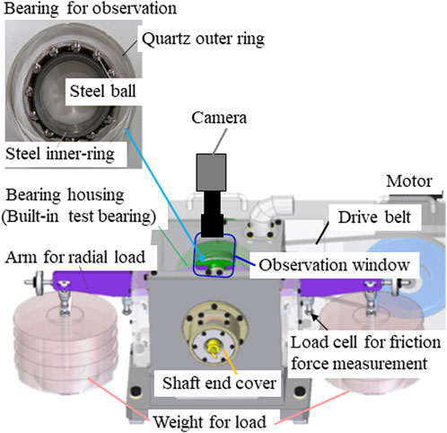
Figure 1. Illustration of test apparatus (Tohyama et al., 2023).
An enlarged cross-sectional view of the bearing housing, including the oil-lubricated structure, is shown in Figure 2. On the test bearing side, an oil supply nozzle with a tip diameter of Φ0.7 mm was installed. Oil was supplied toward the uppermost ball of the test bearing. The oil temperature was controlled to be constant at 60°C at the outlet of the oil supply nozzle by separately adjusting the temperature in an oil bath set. Oil was supplied at a constant rate of 100 mL/min using a roller pump. The oil was a commercially available automatic transmission fluid (ATF: Toyota Auto Fluid WS), which is also used in the transaxles of hybrid EVs. The right side of the bearing housing, shown in Figure 2, was covered with a transparent acrylic cover, whereas the left side was covered with a metal cover. Both covers had clearances between the rotating shafts to prevent contact. An oil drain was placed on one side inside the housing, as shown in Figure 2, and an oil penetration port was placed at a low position in the housing to maintain the oil accumulation below the height of the lower side of the outer ring of the test bearing.
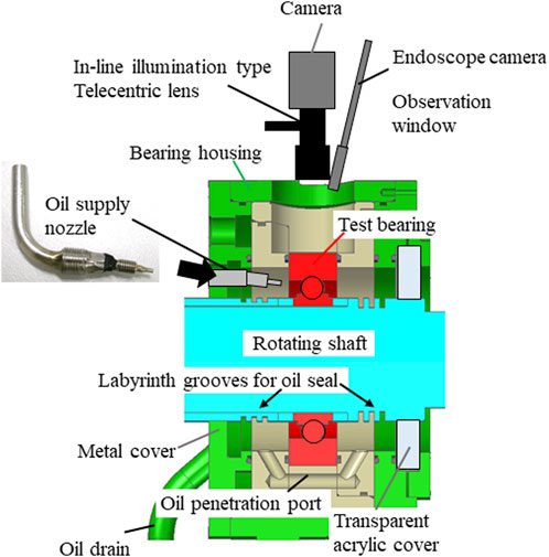
Figure 2. Enlarged cross-sectional view of bearing housing (Tohyama et al., 2023).
The test bearing featured a transparent quartz outer ring with the same track surface shape as an actual commercial 6008-type deep-groove ball bearing (outer diameter: ø68 mm, inner diameter: ø40 mm, width: 15 mm, 12 balls, crown-shaped resin cage) for optical measurement and observation as described in subsequent sections. The inner ring, balls, and cage were made of steel and resin, respectively, from the actual commercial 6008-type deep-groove ball bearing. The track surface of the quartz outer ring was finished to be very smooth (surface roughness Ra of 0.05 μm or less), which is essential for precise measurements. The outer diameter and width of the quartz outer ring were changed from the shape of the 6008-type bearing to match the shape of the other test bearings (which were not used in this study), resulting in dimensions of ø80 and 18 mm, respectively.
Thermocouples were attached at four locations around the outer circumference of the outer ring to monitor the temperature of the bearing. The average of these four readings was used to determine the outer-ring temperatures. When conducting tests with varying shaft rotational speeds, to minimize changes in the bearing temperature at each speed, the rotational speed was initially set to the highest value of the test (approximately 20,000 min-1) for 2 min before starting measurements, and then the speed was gradually reduced. There was a constant radial load of 300 N.
2.2 Oil-film thickness measurements between outer ring raceway and ball surface
The oil-film thickness between the raceway of the quartz outer ring and ball was measured using the three-wavelength optical interference method (Otsuki et al., 2016), as shown in Figure 3. In this method, the three-wavelength light (RGB) was obtained by adjusting white light from a xenon flash lamp through a three-wavelength bandpass filter. These three wavelengths were irradiated onto the ball surface using a liquid light guide and coaxial telecentric lenses, as shown in Figure 2. The raceway of the quartz outer ring was coated with a chromium layer because a partial reflective coating is necessary for the optical interference measurement method. Additionally, silica with a thickness of 300 ± 50 nm (not shown in Figure 3) was coated on top of the chromium layer as a spacer and protective layer. The interference images resulting from the optical path difference between the light reflected by the reflective coating and that reflected by the ball surface (equivalent to half of the oil-film thickness) were captured using a high-resolution 3- complementary metal oxide semiconductor (CMOS) camera for machine vision. The observation area was approximately 3.55 mm (ball rolling direction) × 0.86 mm (axial direction) around the contact area between the ball and raceway on the outer ring of the bearing.
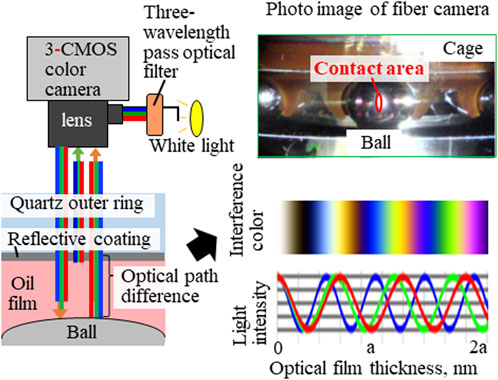
Figure 3. Measurement method of oil-film thickness by three-wavelength optical interferometry (Tohyama et al., 2023).
The optical film thickness was determined by comparing the central interference color at the contact surface of the ball with the optical film thickness color chart shown in Figure 3. In cases with significant variations in the interference color within the contact area, a two-dimensional quantitative analysis using the hue method developed by Tomota et al. (2022) was used to calculate the thickness. The calculated optical film thickness includes the thickness of the reflective and spacer films. To measure the total thickness of the reflective and spacer films, the optical film thickness was determined by observing the interference image at the contact surface in a static state by adding a radial load that did not form an oil film. By subtracting this optical film thickness from the experimentally measured optical film thickness of each test condition, the optical film thickness corresponding to the oil-film thickness was obtained. Finally, the oil-film thickness was calculated by dividing the optical film thickness by the refractive index of the ATF (1.45, measured at an oil temperature of 60°C).
A pulsed illumination with a 2 μs irradiation time and 50 Hz repetition rate was employed to reduce image blur during high-speed motion. The frame rate of the 3-CMOS camera was set to 50 fps and synchronized with the pulse illumination. The shaft rotational speed was finely controlled to synchronize the orbit cycle of the ball revolution with the repetition of pulsed illumination. Consequently, although the balls in the bearing were moving at an extremely high speed, the balls in the videos appear to be stopped or moving in orbit very slowly.
Additionally, an endoscope camera was installed alongside the 3-CMOS camera in the test apparatus, as shown in Figure 2, to observe the white-light image around the rolling ball at approximately 30 and 17 mm in the ball-rolling and axial directions.
2.3 Oil distribution observation by fluorescence method
The oil distributions were observed using a fluorescence method. In the fluorescence method, coumarin-6 was added as a fluorescent agent in a 0.05 wt% concentration. For fluorescence excitation, pulsed ultraviolet (UV)-LED illumination at a wavelength of 405 nm was employed. A liquid-light guide was used to direct the emitted light to the focal point where the condenser lens was attached. Unlike interferometry, the excitation light was irradiated from outside the lens onto the observation target. The pulsed UV-LED illumination was configured with a 2 μs irradiation time and 40 Hz repetition rate to reduce image blur. The video recording was synchronized with the camera frame rate set at 40 fps to match the pulse illumination. The 3-CMOS camera was the same as that used for the oil-film measurement. The observation area was approximately 23.6 mm (ball-rolling direction) × 17.7 mm (axial direction). To enhance the sensitivity of the camera, a binning function was applied, which combined four-pixel image sensors to acquire a single image, resulting in a camera resolution of x: 1032, y: 772.
3 Results and discussion
3.1 Oil-film thickness measurement results
Figure 4 shows examples of interference fringe images caused by oil film formation between the ball and raceway of the outer ring under various shaft rotational speed conditions. The interference fringe image at a rotational speed of 0 min-1 represents the shape near the center of the Hertz contact ellipse. The brown interference color in the central region for a rotational speed of 0 min-1 corresponds to the optical film thickness due to the partially reflective coating (estimated to be a few nanometers thick) and silica coating on the raceway of the quartz outer ring. Focusing on the change in the interference color with increasing rotational speed, color variations from 1,780 to 5,350 min-1 can be observed, indicating an increase in the oil-film thickness as the rotational speed increases. However, between 7,740 and 20,320 min-1, the interference colors remain similar. These results suggest that the oil-film thickness under high-speed conditions becomes constant. Notably, during the measurement at each speed, changes in the interference color were not observed during the 1-min measurement interval. Therefore, the oil-film thickness on the rolling surface remained stable under steady-state conditions.
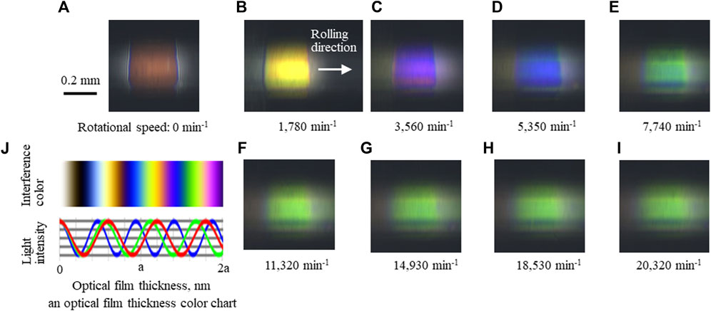
Figure 4. Optical interference images of contact surfaces for each rotational speed of (A) 0, (B) 1,780, (C) 3,560, (D) 5,350, (E) 7,740, (F) 11,320, (G) 14,930, (H), 18,530, and (I) 20,320 min-1 and (J) is an optical film thickness color chart (Tohyama et al., 2023).
In the interference images shown in Figure 4, the upper and lower regions of each image appear dark and interference fringes cannot be observed in these regions. This phenomenon can be attributed to the R-shaped groove on the quartz outer ring, which resembles an actual deep-groove ball bearing. Because of the varying reflection angles caused by the widthwise position of the R-groove and the significant change in distance from the lens, the focus depth deviates, resulting in partial visibility of the interference pattern.
The measured oil-film thickness, calculated from the light interference colors, is shown in Figure 5. For comparison, the dashed line also includes the calculated central oil-film thickness based on the EHL oil-film thickness formula of Chittenden et al. (1985) for fully flooded lubrication conditions. In this calculation, the oil viscosity was estimated to be 0.011 Pa s at a supply oil temperature of 60°C, assuming a constant sliding ratio of 0% for the ball. In these results, the oil-film thickness values at each rotational speed are shown as relative ratios to the calculated central oil-film thickness value at the highest rotational speed of 20,320 min⁻1 in the actual measurement (normalized to 1.0).
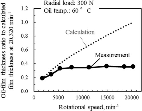
Figure 5. Comparison of oil-film thickness between measurement and calculated values (Tohyama et al., 2023).
At a low-speed range of 1,780–5,350 min⁻1, the measured oil-film thickness values tended to increase as the rotational speed increased, similar to the calculated values. However, at speeds above 7,740 min⁻1, the measured values of the oil-film thickness remained relatively constant regardless of rotational speed. Unlike the assumptions of the EHL theory under fully flooded lubrication conditions, in the high-speed range, the oil-film thickness does not increase, even as the shaft rotation speed (or rolling speed) increases.
Figure 6 shows the friction torque measured simultaneously with the oil-film thickness as a reference, the friction torque obtained during the observation of the oil distribution using the fluorescence method, and the temperature measurements at the outermost periphery of the quartz outer ring. The measured friction torque values during the oil-film thickness measurement and oil-distribution observation were similar, indicating good reproducibility of the friction torque in this test. The friction torque of the deep-groove ball bearing used in this test tended to increase with rotational speed.
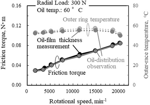
Figure 6. Friction torque measured during oil-film thickness measurements and oil-distribution observations (Tohyama et al., 2023).
3.2 Oil distribution observations using endoscope camera
The oil distribution around the ball was captured using an endoscope camera equipped with pulsed white-light illumination, specifically utilizing three-wavelength light. Snapshot images extracted from the videos are presented in Figure 7. In Figure 7A, the positions of the oil supply nozzle and the outer ring raceway are marked for reference. Figure 7H indicates the cage’s shape with brown lines for reference. The red color in the images represents the ATF used in this test. Under the low-speed condition with a rotational speed of 1,780 min⁻1, the area around the rolling ball was nearly fully immersed in oil (ATF). However, at speeds exceeding 3,560 min⁻1, as the rotational speed increased, the oil near the ball inlet (on the right side of the ball) gradually became cloudy white, indicating an increasing presence of air bubbles in the oil due to aeration. The cloudiness of the oils at the ball inlets reveals that the number of air bubbles mixed in the oils tended to rise as the rotational speed approached 7,700 min⁻1. Additionally, oil starvation was observed at the ball outlet (left side of the images), and these oil-starved regions tended to expand with increasing rotational speed. The aeration of the inlet oil and the expansion of the oil-starved regions on the raceway are considered contributing factors that prevent the increase in oil-film thickness under high-speed conditions.
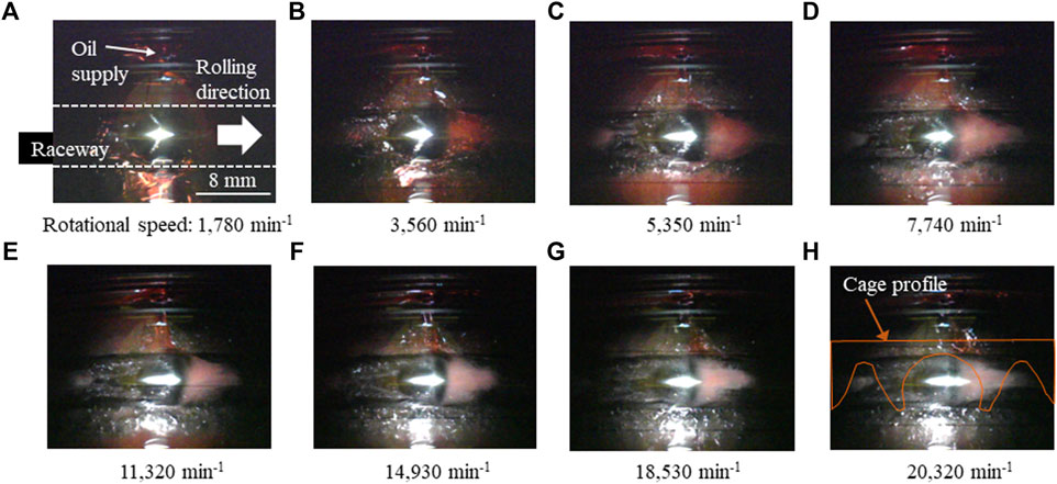
Figure 7. White-light images of oil distributions observed by using endoscope camera under rotational speeds of (A) 1,780, (B) 3,560, (C) 5,350, (D) 7,740, (E) 11,320, (F) 14,930, (G), 18,530, and (H) 20,320 min-1 (Tohyama et al., 2023).
3.3 Oil distribution observations using fluorescence method
The oil distributions observed at various rotational speeds using the fluorescence method are depicted in Figure 8. These observations were facilitated by synchronizing the revolution period of the ball with the pulsed illumination, enabling real-time observation. In Figure 8A, the positions of the ball and the edges of the raceway on the outer ring are delineated by dashed lines, with the rolling directions of the balls indicated on the right side of the images. The bright areas signify the presence of substantial amounts of oil. Oil was supplied from the point labeled “oil supply” in Figure 8A towards the ball. Near the center of the ball in the rolling direction, dark regions indicating the absence of oil were consistently observed in all images. These regions are considered the contact areas between the ball and outer ring. The two-dotted dashed line in Figure 8H illustrates the shape of the crown-type cage used for the test bearing.
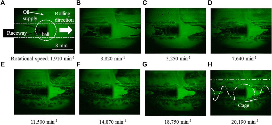
Figure 8. Fluorescence images of oil distributions observed by using 3-CMOS camera under rotational speeds of (A) 1,920, (B) 3,820, (C) 5,250, (D) 7,640, (E) 11,500, (F) 14,870, (G) 18,750, and (H) 20,190 min-1 (Tohyama et al., 2023).
Under low-speed conditions with a rotation speed of 1,910 min-1, similar to the observations made using the endoscope camera described in Section 3.2, the ball inlet (on the right side of the ball) was filled with oil. However, the amount of oil at the ball inlet tended to decrease with increasing rotational speed. Oil starvation occurred at the ball outlet side. As the rotational speed increased, the starvation region tended to expand toward the next ball. Although some details may be difficult to discern in the static image shown in Figure 8, in the captured video for rotational speeds exceeding 7,640 min-1 (as shown in Figures 8D–H), the oil flow from the oil supply was deflected by the rolling ball, causing the direct inflow oil supply from the side nozzle to the ball inlet to cease. The oil distribution shape at the ball inlet spread triangularly from the front of the ball toward the ball, and oil was supplied from the space between the cage claws that held the ball in the cage. Therefore, even with oil supply nozzles provided on the side of the ball, the oil supply to the ball in a deep-groove ball bearing during high rotational speeds primarily occurs through the space in the cage, rather than being directly supplied from the side. This oil flow is a specific phenomenon unique to ball bearings and depends on the retainer shape. These results underscore the importance of observations using actual bearing shapes for comprehensive bearing evaluations, as replicating these oil-flow phenomena using simple ball-on-disk tests is challenging.
Focusing on the correlation between the oil distribution and oil-film thickness, it can be assumed that the increment rate in the oil-film thickness decreases with increasing rotational speed, as shown in Figure 4, corresponding to a decrease in the amount of oil at the ball inlet.
These measurements and observations yield new, clarified findings that go beyond speculations or predictions made by many researchers. These findings, which could not be obtained from previous observations at rotational speeds up to 6,000 min-1 as described in the introduction section, were made possible by experiments conducted under high-speed conditions up to 20,000 min-1. However, the methods introduced above also have limitations, such as the lack of examination of the oil-film thickness between balls and the inner ring, as well as the oil distribution on the inner-ring side. Utilizing other measurement and observation methods evolved from those described in Section 1, along with CAE calculations and prediction techniques improved by incorporating new findings, may also be crucial in fully understanding the lubrication conditions in high-speed ball bearings.
4 Conclusion
To clarify the lubrication conditions of deep-groove ball bearings for eAxles of EVs at high rotational speeds, a new test apparatus was developed. This apparatus is capable of simultaneously measuring the friction torque and oil-film thickness on the rolling balls and visualizing the oil distribution around the balls on the raceway of the outer ring at rotational speeds of up to 20,000 min-1. Based on the results obtained by measuring the oil-film thickness and observing the oil distribution in a 6008-type ball bearing supplied with oil from a nozzle placed on the side of the bearing (Tohyama et al., 2023), the following findings were obtained.
1) At high rotational speeds, the oil-film thickness on the surface of the rolling ball in deep-groove ball bearings does not increase, in contrast to the EHL theory under fully flooded conditions. The oil-film thickness became constant at rotational speeds exceeding approximately 7,700 min-1.
2) At high rotational speeds, oil supplied from the side of the orbit of the rolling ball was obstructed by the moving balls and cage, incurring oil starvation. In a deep-groove ball bearing with a crown-shaped cage, the oil was mainly supplied to the rolling balls from the inner ring side through the space between the cage claws that held the ball.
3) Oil supplied to the rolling balls from the inner ring side was mixed with air bubbles at rotational speeds exceeding 2,000 min-1. The amount of mixed air tended to increase as the rotational speed increased to approximately 7,700 min-1.
4) The insufficient oil supply at the ball inlet (resulting in oil starvation) and presence of air bubbles in the oil (causing a decrease in the effective oil viscosity on the rolling surface) were assumed to prevent an increase in oil-film thickness despite increasing rotational speeds in the high-speed range.
The findings of this study will contribute to the development of multibody dynamic technology for high-speed ball bearings necessary in EVs (JTEKT, 2023). The measurement and observation techniques described in this study can be utilized in future studies to enhance the accuracy of computational fluid dynamics analysis methods for calculating oil flow. Moreover, these techniques may enable the design of optimal high-speed deep-groove ball bearings for eAxles, with features such as low friction torque performance and seizure prevention.
Data availability statement
The original contributions presented in the study are included in the article/supplementary material, further inquiries can be directed to the corresponding author.
Author contributions
MT: Conceptualization, Investigation, Methodology, Visualization, Writing–review and editing, Validation, Writing–original draft. YO: Data curation, Investigation, Methodology, Visualization, Writing–review and editing. MH: Conceptualization, Supervision, Writing–review and editing. HM: Supervision, Writing–review and editing. TT: Supervision, Writing–review and editing. KH: Supervision, Writing–review and editing. TO: Conceptualization, Project administration, Supervision, Writing–review and editing. HS: Resources, Writing–review and editing. MY: Resources, Writing–review and editing. NS: Conceptualization, Investigation, Project administration, Supervision, Writing–review and editing.
Funding
The author(s) declare that financial support was received for the research, authorship, and/or publication of this article. This study was funded by Toyota Central R&D Labs., Inc. and JTEKT CORPORATION. The funders were involved in the study titled “Visualization of oil-lubrication ball bearings at high rotational speeds.”
Conflict of interest
Authors MT, YO, HS, MY, and NS are employed by Toyota Central R&D Labs., Inc., while MH, HM, TT, KH, and TO are employed by JTEKT corporation.
The authors declare that this study received funding from Toyota Central R&D Labs., Inc. and JTEKT CORPORATION. The funder had the following involvement in the study: the decision to submit it for publication.
Publisher’s note
All claims expressed in this article are solely those of the authors and do not necessarily represent those of their affiliated organizations, or those of the publisher, the editors and the reviewers. Any product that may be evaluated in this article, or claim that may be made by its manufacturer, is not guaranteed or endorsed by the publisher.
References
Arya, U., Peterson, W., Sadeghi, F., Meinel, A., and Grillenberger, H. (2023b). Investigation of oil flow in a ball bearing using Bubble Image Velocimetry and CFD modeling. Tribol. Int. 177, 107968. doi:10.1016/j.triboint.2022.107968
Arya, U., Sadeghi, F., Aamer, S., Meinel, A., and Grillenberger, H. (2023a). In situ visualization and analysis of oil starvation in ball bearing cages. Tribol. Trans. 66 (5), 965–978. doi:10.1080/10402004.2023.2253867
Cann, P. M. E., Damiens, B., and Lubrecht, A. A. (2004). The transition between fully flooded and starved regimes in EHL. Tribol. Int. 37 (10), 859–864. doi:10.1016/j.triboint.2004.05.005
Cen, H., and Lugt, P. M. (2019). Film thickness in a grease lubricated ball bearing. Tribol. Int. 134, 26–35. doi:10.1016/j.triboint.2019.01.032
Chen, H., Liang, H., Wang, W., and Zhang, S. (2023). Investigation on the oil transfer behaviors and the air-oil interfacial flow patterns in a ball bearing under different capillary conditions. Friction 11 (2), 228–245. doi:10.1007/s40544-021-0592-3
Chen, H., Wang, W., Liang, H., and Ge, X. (2022). Observation of the oil flow in a ball bearing with a novel experiment method and simulation. Tri. Int. 174, 107731. doi:10.1016/j.triboint.2022.107731
Chennaoui, M., Fowell, M., Liang, H., and Kadiric, H. (2022). A novel set-up for in situ measurement and mapping of lubricant film thickness in a model rolling bearing using interferometry and ratiometric fluorescence imaging. Tribol. Lett. 70 (85), 85. doi:10.1007/s11249-022-01625-z
Chittenden, R. J., Dowson, D., Dunn, J. F., and Taylor, C. M. (1985). A theoretical analysis of the isothermal elastohydrodynamic lubrication of concentrated contacts. II. General case, with lubricant entrainment along either principal Axis of the hertzian contact ellipse or at some intermediate angle. Proc. R. Soc. A 397 (1813), 271–294. doi:10.1098/rspa.1985.0015
Desnica, E., Ašonja, A., Radovanović, L., Palinkaš, I., and Kiss, I. (2022). Selection, dimensioning and maintenance of roller bearings. 31st international conference on organization and technology of maintenance (OTO 2022). OTO 2022. Lect. Notes Netw. Syst. 592, 133–145. doi:10.1007/978-3-031-21429-5_12
Dwyer-Joyce, R. S., Reddyhoff, T., and Drinkwater, B. W. (2004). Operating limits for acoustic measurement of rolling bearing oil film thickness. Tribol. Trans. 47 (3), 366–375. doi:10.1080/05698190490455410
Guangteng, G., Cann, P. M., and Spikes, H. A. (1992). A study of parched lubrication. Wear 153 (1), 91–105. doi:10.1016/0043-1648(92)90263-8
Hengst, J., Werra, M., and Küçükay, F. (2022). Evaluation of transmission losses of various battery electric vehicles. Automot. Innov. 5, 388–399. doi:10.1007/s42154-022-00194-0
Houpert, L. (2016). Hydrodynamic load calculation in rolling element bearings. Tribol. Trans. 59 (3), 538–559. doi:10.1080/10402004.2015.1090043
Jablonka, K., Romeo Glovnea, R., and Jeroen Bongaerts, J. (2018). Quantitative measurements of film thickness in a radially loaded deep-groove ball bearing. Tribol. Int. 119, 239–249. doi:10.1016/j.triboint.2017.11.001
JTEKT (2023). JTEKT ENGINEERING JOURNAL No.1019E. Model based development for BEV high-speed ball bearing. Available at: https://www.jtekt.co.jp/e/engineering-journal/1019/1019-17.html (Accessed March 29, 2024).
Kamamoto, S., Murata, J., and Shishihara, Y. (2022). Study on low torque deep groove ball bearing by cage profile optimization. JTEKT Eng. J. No. 1018E, 22–34. Available at: https://www.jtekt.co.jp/e/engineering-journal/1018/1018-06.html (Accessed March 30, 2024).
Kostal, D., Sperka, P., Svoboda, P., Krupka, I., and Hartl, M. (2017). Influence of lubricant inlet film thickness on elastohydrodynamically lubricated contact starvation. J. Tribol. 139, 051503. doi:10.1115/1.4035777
Liang, H., Zhang, Y., and Wang, W. (2022). Influence of the cage on the migration and distribution of lubricating oil inside a ball bearing. Friction 10 (7), 1035–1045. doi:10.1007/s40544-021-0510-8
Maruyama, T., Maeda, M., and Nakano, K. (2019). Lubrication condition monitoring of practical ball bearings by electrical impedance method. Tribol. Online 14 (5), 327–338. doi:10.2474/trol.14.327
Maruyama, T., and Tsuyoshi, S. (2015). Relationship between supplied oil flow rates and oil film thicknesses under starved elastohydrodynamic lubrication. Lubr 3 (2), 365–380. doi:10.3390/lubricants3020365
Matsumoto, K., Koga, H., Ono, Y., and Mihara, Y. (2021). Calculation of oil film thickness on bearing raceway grooves by measuring raceway outer ring temperature. SAE Tech. Pap. 2021-01-0342. doi:10.4271/2021-01-0342
Nagai, H., Kawamoto, N., Horiguchi, K., Yoda, T., Hiyoshi, M., and Yamamoto, M. (2023). Development of powertrain system and battery for BEV. SAE Tech. Pap. 2023-01-0518. doi:10.4271/2023-01-0518
Noda, T., Shibasaki, K., Miyata, S., and Taniguchi, M. (2020). X-ray CT imaging of grease behavior in ball bearing and numerical validation of multi-phase flows simulation. Tribol. Online 15 (1), 36–44. doi:10.2474/trol.15.36
Nogi, T. (2015). An analysis of starved EHL point contacts with reflow. Tribol. Online 10 (1), 64–75. doi:10.2474/trol.10.64
Otsuki, M., Kitagawa, K., Izumi, T., and Tohyama, M. (2016). Development of three-wavelength interferometry (Part 1) -Calibration-less oil thickness profile measurement by thin film interference color analysis-. Proc. Tribol. Conf. 2016 Spring Tokyo, B9. (in Japanese).
Peterson, W., Russell, T., Sadeghi, F., and Berhan, M. T. (2021). Experimental and analytical investigation of fluid drag losses in rolling element bearings. Tribol. Int. 161, 107106. doi:10.1016/j.triboint.2021.107106
Reddyhoff, T., Choo, J. H., Spikes, H. A., and Glovnea, R. P. (2010). Lubricant flow in an elastohydrodynamic contact using fluorescence. Tribol. Lett. 38, 207–215. doi:10.1007/s11249-010-9592-6
Sakai, K., Ayame, Y., Iwanami, Y., Kimura, N., and Matsumoto, Y. (2021a). Observation of grease fluidity in a ball bearing using neutron imaging technology. Tribol. Online 16 (2), 146–150. doi:10.2474/trol.16.146
Sakai, K., Iki, H., Ayame, Y., Iwanami, Y., Kimura, N., and Matsumoto, Y. (2021b). Observation of grease fluidity in a ball bearing using neutron imaging technology (Part 2) -in situ observation of bearing with rotation-. Proc. Tribol. Conf. 2021 Autumn Matsue, D28. (in Japanese).
Spikes, H. (2014). Basics of EHL for practical application. Lubr. Sci. 27 (1), 45–67. doi:10.1002/ls.1271
Tohyama, M., Ohmiya, Y., Hirose, M., Matsuyama, H., Toda, T., Hasegawa, K., et al. (2023). Measurement of oil-film thickness and observation of oil-distribution in high-speed deep groove ball bearing. J. Jpn. Soc. Tribol. 68 (8), 577–585. (in Japanese). doi:10.18914/tribologist.22-00028
Tomota, T., Tohyama, M., and Yagi, K. (2022). Elucidation of contact state on various rough surfaces via highly robust colorimetric optical interferometry. Sci. Rep. 12 (178), 178. doi:10.1038/s41598-021-04104-y
Wan Ibrahim, M. K., Gasni, D., and Dwyer-Joyce, R. S. (2012). Profiling a ball bearing oil film with ultrasonic reflection. Tribol. Trans. 55 (4), 409–421. doi:10.1080/10402004.2012.664836
Wedeven, L. D., Evans, D., and Cameron, A. (1971). Optical analysis of ball bearing starvation. J. Lubr. Tech. 93 (3), 349–361. doi:10.1115/1.3451591
Wu, W., Hu, C., Jibin Hu, J., and Yuan, S. (2016). Jet cooling for rolling bearings: flow visualization and temperature distribution. Appl. Therm. Eng. 105, 217–224. doi:10.1016/j.applthermaleng.2016.05.147
Yokota, K. (2020). Technological trends and outlook of automotive bearing. JTEKT Eng. J. 1017E, 25–35. Available at: https://www.jtekt.co.jp/e/engineering-journal/assets/1017/1017e_05.pdf (Accessed March 29, 2024).
Zhang, X., and Glovnea, R. (2020). Grease film thickness measurement in rolling bearing contacts. Proc. Institution Mech. Eng. Part J J. Eng. Tribol. 235 (7), 1430–1439. doi:10.1177/1350650120961278
Keywords: ball bearing, lubrication, oil-film thickness measurement, oil distribution, starvation, interferometrytechniques, fluorescence method, EHL (elastohydrodynamic lubrication)
Citation: Tohyama M, Ohmiya Y, Hirose M, Matsuyama H, Toda T, Hasegawa K, Onizuka T, Sato H, Yokoi M and Sato N (2024) Visualization of oil-lubrication ball bearings at high rotational speeds. Front. Mech. Eng 10:1416656. doi: 10.3389/fmech.2024.1416656
Received: 12 April 2024; Accepted: 13 May 2024;
Published: 07 June 2024.
Edited by:
Taisuke Maruyama, NSK Ltd., JapanReviewed by:
Aleksandar Ašonja, Business Academy University, SerbiaSlavica Miladinovic, University of Kragujevac, Serbia
Copyright © 2024 Tohyama, Ohmiya, Hirose, Matsuyama, Toda, Hasegawa, Onizuka, Sato, Yokoi and Sato. This is an open-access article distributed under the terms of the Creative Commons Attribution License (CC BY). The use, distribution or reproduction in other forums is permitted, provided the original author(s) and the copyright owner(s) are credited and that the original publication in this journal is cited, in accordance with accepted academic practice. No use, distribution or reproduction is permitted which does not comply with these terms.
*Correspondence: Mamoru Tohyama, tohyama@mosk.tytlabs.co.jp