An analytical and in silico strategy for estimating maximum stress and fatigue life of bone plates under in vivo loads: a rationale for regulatory testing
 Federico Andrea Bologna
 Alberto Luigi Audenino
 Mara Terzini
- 1Department of Mechanical and Aerospace Engineering, Politecnico di Torino, Turin, Italy
- 2PolitoBIOMed Lab, Politecnico di Torino, Turin, Italy
Despite the innovations introduced by locking compression plates (LCP), implant failures still occur due to fatigue fractures caused by cyclic loads. The endurance of LCP, especially in lower limb plates subjected to ambulatory cyclic loads, is a critical factor that needs to be understood. Unfortunately, there is limited information available on the fatigue failure of LCP. The fatigue behavior is a crucial aspect of mandatory mechanical tests for regulatory purposes, which aim to determine the load at which the plate withstands under a specific number of cycles, known as the runout condition. The current test standards, such as ASTM F382, only provide the setup configuration without furnishing explicit guidelines regarding the required fatigue strength of the bone plate in the runout condition. The determination of the minimum level of in vivo performance that the plate must fulfill remains an open issue, which is frequently addressed by the direct comparison with predicate devices. To address this issue, this study proposes a rationale that combines analytical and in silico approaches to estimate the maximum stress and fatigue life of a bone plate under in vivo loads. Four-point bending tests were conducted on a diaphyseal femoral plate to determine the experimental runout load. Analytical and finite element (FE) models were first implemented to replicate the four-point bending setup and to calculate the maximum stress on the plate. The Goodman and Gerber criteria were exploited to determine the mean stress effect due to the four-point bending setup and to verify the predicted number of cycles. In addition, the force-displacement curves of the FE model were validated by means of experimental results. Analytical and FE models were then applied to calculate the maximum stress and assess the performance of the implanted plate under in vivo loading conditions. In the implanted plate condition, a mean number of cycles higher than 1.5 million was estimated. Analytical models showed good performance compared with in silico strategies, exhibiting errors below 6%. The comparison between the obtained results provides valuable insights for constructing a robust rationale to support the regulatory process in order to obtain CE marking.
1 Introduction
Modern locking compression plates (LCP) have combined the advantages of the dynamic compression plate (DCP) with the ability to transmit the load without compression between the plate and bone surface. In regular DCP the screws must be pressed into the holes to obtain a stable fixation, causing the well-known problems of vascularization of the area under the plate with the subsequent development of unfavorable conditions for bone healing. In LCP, on the other hand, the screws are directly fastened to the plate, which acts as an internal fixator. The load is then transmitted by the plate-screw system, while maintaining a gap between the plate and the bone. This design preserves vascularity in the affected area, ensuring better blood supply for optimal healing (Hönig and Merten, 1996). Although several design changes have been introduced over the years, implant failures still occur. These failures are rarely due to a single case of overloading, but rather because of fatigue failures due to cyclic loads (Kanchanomai et al., 2010). Research findings indicate that metallic fixation devices are often subjected to high stress, which can potentially cause either catastrophic overloading or cyclic fatigue (Azevedo, 2003). In fact, the endurance of the LCP is a critical factor to consider, especially for plates designed for lower limbs, as they experience cyclic loads during ambulation that can potentially compromise the integrity of the plate. For these purposes, different studies have focused on reproducing the post-surgical conditions that led to the failure of the implant (Antoniac et al., 2019; Terzini et al., 2020a). However, the available information on fatigue failure of the LCP is limited.
Several research studies on bone and/or plate primarily focus on experimental investigations. Kanchanomai et al. (2008) experimentally evaluated the fatigue failure of an LCP fixed along a diaphyseal femoral fracture. However, in this study, the evaluation of the implanted plate was conducted for only a single cycle, which corresponded to the maximum load applied on the femoral head alone. This limitation arises from the increased complexity introduced by the inclusion of muscle forces in the experimental setup. In addition, composite femurs are not designed to withstand cyclic loads. Instead, the fatigue characteristics were assessed using a four-point bending configuration. A similar experiment was conducted by Hoffmeier et al. (2011) to investigate the correlation between endurance and working length.
ASTM F382 (ASTM International, 2017) is the commonly used test standard for metallic bone plates, which employs a four-point bending setup to determine the primary mechanical properties of the bone plate. However, this standard does not provide any indication of the fatigue properties that the bone plate should meet based on the intended anatomical region. The Food and Drug Administration (FDA) recently issued the first criteria for quantifying plate performance (Food and Drug Administration, 2022). Again, this guideline refers only to static tests and does not include any indication regarding plate endurance.
In this context, several studies have focused on the test condition, neglecting the loads that occur in vivo. Indeed, in silico methodologies have been used to determine the stress distributions on generic bone plates under four-point bending in order to evaluate different designs (Drátovská et al., 2021) or the effect of thread removal and screw hole offsetting (Muthusamy et al., 2022). On the contrary, other studies focused on the post-surgical conditions that led to implant failure by subjecting the plate to the loads present in vivo. Few examples are the work of (Terzini et al., 2020a), where unconventional loading situations, such as those caused by stumbling and in the presence of incomplete bone healing, were statically evaluated in a periprosthetic femur plate system, and the work of Antoniac et al. (2019), which performed a failure analysis on a humeral plate exploring various loading scenarios through FE analysis to investigate the mechanism that led to the failure of the plate. In this latter, the fatigue assessments were introduced by inputting the obtained values of maximum equivalent stress into a commercial software to estimate the number of cycles based on the loading condition using the Goodman criterion. Other basic fatigue assessments can be found in (Nakhaei et al., 2023) where FE analysis was used to investigate the fatigue characteristics of hybrid reconstruction plates intended for the treatment of segmental defects of the mandible, employing conventional S-N curves (stress amplitude vs. number of cycles to failure).
To the authors’ knowledge, no study has compared the test conditions described by the ASTM standard with the conditions to which the plate will be subjected once implanted. In addition, analytical approaches are rarely used for the evaluation of the stress distribution and the subsequent prediction of fatigue behavior. An instance of analytical evaluation of stresses was performed on a simplified diaphyseal femoral plate, revealing a good correlation with outcomes obtained through a commercial FE software, but neglecting any fatigue prediction (Kenedi and Vignoli, 2017).
However, the determination of the minimum level of in vivo performance and related fatigue life that the plate must fulfil remains an open issue (Bologna et al., 2021), which is frequently addressed through direct comparison with predicate devices. To tackle this challenge, the present work proposes a rationale that combines two different approaches, analytical and in silico, to estimate the maximum stress of a bone plate and its fatigue life under in vivo loads. This framework aims to provide a valuable rationale to guide the regulatory process and obtain CE marking.
2 Materials and methods
2.1 Four-point bending
In a previous study, a series of four-point bending tests were conducted according to the ASTM F382 standard, in order to determine the experimental runout load of a diaphyseal femoral plate in pure titanium (Bologna et al., 2022). The load that enables the execution of one million cycles, the runout condition, was determined in accordance with the ASTM standard. The tests were carried out with an R-ratio of 0.1, meaning that the minimum load of the sinusoidal waveform was calculated as 10% of the maximum load. At the end of the cyclic tests, a runout load (L) of 1,200 N was identified.
Two approaches were employed to model the four-point bending setup: an initial analytical model was implemented to calculate the maximum stress on the most critical hole of the femoral plate that had already been tested experimentally (Bologna et al., 2022). Subsequently, a comparison with a finite element (FE) model was performed to verify the accuracy of the analytical approach.
2.1.1 The analytical twin
The bending moment (M) was computed from Eq. 1 based on the experimental runout load (L):
where h = 38 mm is the loading span in the four-point bending setup for the tested plate (Figure 1).
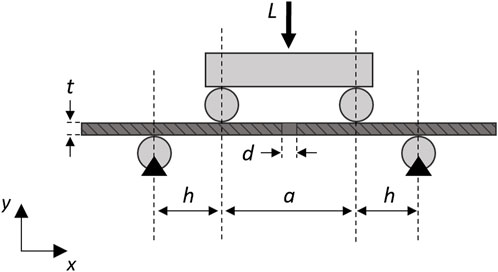
FIGURE 1. Schematic diagram of the analytical model of the simplified plate (dark gray) with a single central hole in the four-point bending configuration (light gray). A longitudinal section was depicted to visualize the screw hole. Black triangles represent fixed supports.
In the analytical model, it was assumed that under the implant conditions only one screw hole would be present at the fracture point and the stress value does not depend on the longitudinal position, since the moment remains constant in the region between the loading rollers.
The maximum stress
where t = 5.12 mm represented the thickness of the plate,
2.1.2 The in silico twin
A FE model (Figure 2) of the experimental setup was then realized in HyperMesh 2019 (Altair Engineering, Troy, United States). The rollers were implemented as rigid cylindrical surfaces, while the material of the bone plate, manufactured from medical grade 4 titanium (International Organization for Standardization, 2018), was considered linear elastic. The Young’s modulus of the plate has been calibrated through experimental static testing to achieve a satisfactory overlap of the force-displacement curve. The ultimate tensile strength (
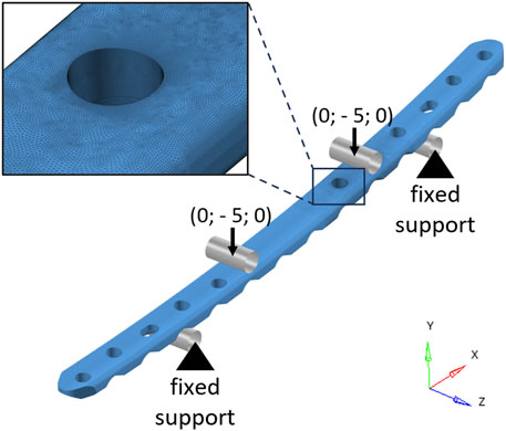
FIGURE 2. Finite element model of the bone plate in the four-point bending configuration. The cylindrical rigid surfaces used to model the rollers are depicted in gray. Black arrows represent the imposed displacements (mm). In the top-left corner, a zoomed-in view of the mesh in the area around the critical hole is shown.
2.2 Implanted plate
In order to determine whether the stress identified by the ASTM standard is adequate to withstand in vivo applications, the analytical and FE approaches have been replicated to calculate the maximum stress of the bone plate at the anatomical implant site. As previously mentioned, the tested plate was designed to be implanted in the human femoral diaphysis, the area where FDA requires the highest performance as it is subject to the highest loads (Food and Drug Administration, 2022).
2.2.1 The analytical twin
The bone plate was placed on an L-size femur geometry (Sawbones Europe AB, Malmö, Sweden) by using SolidWorks 2020 (Dassault Systèmes, Vélizy-Villacoublay, France), and a fracture gap (lb) of 6 mm was inserted into the femoral diaphysis. The femur-plate construct was converted into an STL file to measure with MATLAB R2020b (MathWorks, Natick, United States) the main distances useful for building the analytical model. A 2-D analytical model was then realized by means of free-body diagrams around the center of the plate hole (C) where the experimental failure occurred during four-point bending tests under loads exceeding the runout condition (Figure 3A). The plane intersecting the center of the critical hole (C), the greater trochanter (B), and the center of the femoral head (A) was considered as the primary plane. The section corresponding to the critical hole was assumed to be located near a growing bony callus (i.e., positioned at the fracture gap level). This region (Figure 3B) was implemented through two linear springs, representing the axial stiffnesses of the plate (
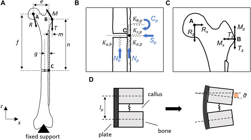
FIGURE 3. (A) Analytical model of the implanted bone plate on

TABLE 1. Main parameters determined for the analytical model of the bone-plate construct.
From the free-body diagram on point C, the following relationships can be derived:
Assuming the vertical displacements of the bone (
where g was the distance between the femoral diaphyseal axis and the plate longitudinal axis.
It is then feasible to write the loads acting on the bone (Nb) and plate (Np, Sp, and Cp)as follows:
By substituting Cp from Eq. 10 into Eq. 5, it is possible to solve for Nb to obtain Np and Sp.
Finally, the von Mises equivalent stress (σeq) was calculated as:
where σb = Cp(t/2)/J, σn = Np/Ap, and σs = Sp/Ap represent the bending stress, the normal stress, and the shear stress, respectively. While
2.2.2 The in silico twin
The in silico replica (HyperMesh 2019; Altair Engineering, Troy, United States) of the femur-plate construct was realized starting from the same geometry employed for the analytical model. The femur was modeled with cortical bone only and the plate was fixed to the bone through the two holes corresponding to the working length of the analytical model (Figure 4). Two bi-cortical screws were modeled with rigid elements. The bony callus was considered through a linear spring with stiffness equivalent to about 6% of the axial stiffness of the femur cortical bone.
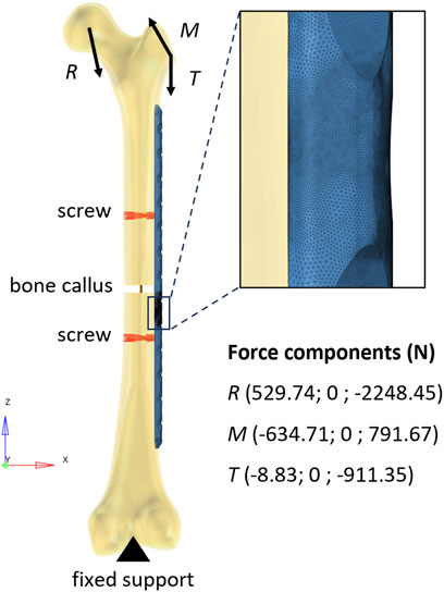
FIGURE 4. Finite element model of the bone-plate construct. The rigid elements used to model the screws are depicted in red. The vertical segment in dark yellow represents the linear spring that models the bone callus. In the top-right corner, a zoomed-in view of the mesh in the area around the critical hole is shown.
The distal end of the femur was constrained in all degrees of freedom (Inacio et al., 2022) and loads measured during normal walking were applied to the femur (Bergmann et al., 2001) using only the 2-D components employed in the analytical calculation. The reaction force acting on the femoral head and the muscle forces were applied as a ramp to reach their maximum values (corresponding to 45% of the step cycle). Loads were distributed over the femoral head and the greater trochanter using rigid elements. While a second-order tetrahedral mesh with a size of 1 mm and a refinement of 0.2 mm in working length was generated for the plate (as well as in the four-point bending condition), the femoral bone was meshed according to Ramos and Simões (2006) using a regular second-order tetrahedral mesh with an average edge length of 2 mm. Abaqus 2019 (Dassault Systèmes, Vélizy-Villacoublay, France) was used as solver.
2.3 Fatigue evaluation
The identified maximum stresses in the analytical and FE models were first used to verify the number of cycles with respect to the experimental cyclic test performed according to the standard and then to predict the in vivo fatigue life of the implanted plate. For fatigue analysis, two stress-life approaches have been employed to identify a range of number of cycles instead of a single value. Firstly, the nominal alternating stress
where
Due to the high-notch sensitivity of materials with a uniform fine-grained matrix (Junivall and Marshek, 2017), a conservative approach was taken by considering the fatigue factor
where
The fatigue limit was set equal to 0.5
The constants A and b were obtained by imposing the straight-line passage for the oligocyclic fatigue (N = 103) limit and the runout condition (N = 106). Assuming that the oligocyclic endurance limit was equal to 90% of the static failure value (Rossetto, 2000), the point at 103 cycles was determined as (Eq. 15):
The obtained parameters are reported in Table 2.
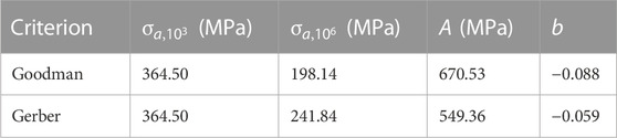
TABLE 2. Principal parameters are determined for the calculation of the number of fatigue cycles according to the Goodman and Gerber criteria.
3 Results
3.1 Four-point bending
While analytical calculations indicated that the maximum stress was equal to 898.1 MPa in the four-point bending setup, the FE analysis revealed a peak stress of 857.8 MPa at the critical hole (Figure 5).
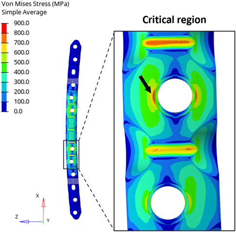
FIGURE 5. (Left) Distribution of equivalent stresses (von Mises) in the four-point bending condition. (Right) Zoomed-in view of the region around the critical hole and the peak location (black arrow).
The stress concentration factor was then derived from the results of the FE analysis and was compared with the one used in the analytical calculation (
The consistency of the FE model in the static four-point bending condition was confirmed with the experimental tests obtained in previous work (Bologna et al., 2022): the force-displacement curve achieved from the in silico analysis fell within the range covered by the experimental results (Figure 6).
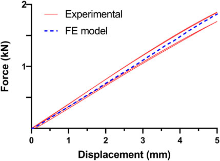
FIGURE 6. Comparison of experimental and in silico force-displacement curves obtained in the four-point bending condition. The four curves in red resulted from experimental tests obtained in previous work (Bologna et al., 2022), while the dashed curve in blue is derived from the FE model.
3.2 Implanted plate
In the implanted plate condition, the analytical evaluation showed a maximum von Mises stress equal to 768.6 MPa. On the other hand, Figure 7 depicts the results obtained from the FE analysis. It is possible to observe that the maximum stress in the proximity of the critical hole is higher than the analytical calculation, showing a peak in the von Mises stress distribution of 811.7 MPa.
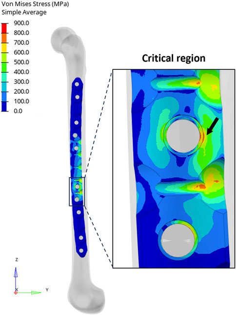
FIGURE 7. (Left) Distribution of equivalent stresses (von Mises) in the implanted plate condition. (Right) Zoomed-in view of the region around the critical hole and the peak location (black arrow).
In this case, the error of the analytical calculation with respect to the FE model increases to 5.3%. It was not possible to compare the stress concentration factors due to the complex loading condition.
3.3 Fatigue evaluation
The estimated range of number of cycles (N) obtained under four-point bending and implanted plate conditions in accordance with the Goodman and Gerber criteria is reported in Figure 8. From the results of the four-point bending condition, it can be observed that the predicted range is correctly identified in both models. The analytical model, because of higher stress, showed a range with a maximum limit slightly below the runout threshold of one million cycles and an average of 575 thousand cycles. In the FE model, the average value of the predicted range of cycle number is approximately one million, demonstrating once again the reliability of this approach.
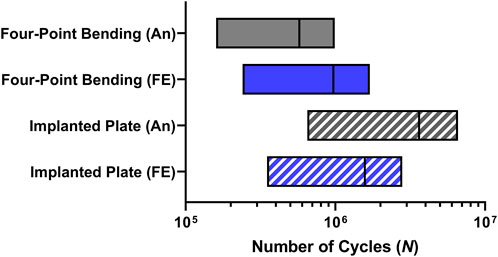
FIGURE 8. Number of cycles (N) range predictions in the critical plate hole obtained from analytical (An) and finite element (FE) models in both four-point bending and implanted plate conditions.
Moving to the model of the implanted plate, the predictions showed encouraging results. Indeed, the analytical model is expected to exhibit a mean fatigue life above 3 million cycles, while incorporating the results of the FE analysis would still yield a mean cycle number above 1.5 million.
4 Discussion
In this work, two different approaches, analytical and in silico, were implemented to achieve a rationale for the regulatory process of a femoral osteosynthesis plate. The four-point bending setup of a previously conducted experimental evaluation was first replicated analytically and in the finite element environment. Through the comparison with experimental results, it was possible to verify the outcomes of the created models. The analytical model produced a more conservative stress value compared to the FE analyses, which proved to be consistent with the experimental expectations. Indeed, the analytical methods applied in this study involve significant approximations, such as the assumption of no reduction in stress concentration factor due to fatigue for the hole (
The maximum stress obtained was close to the ultimate strength of the plate material (900 MPa). In the four-point bending condition, the stress in the screw hole was lower than that observed by Muthusamy et al. (2022) in the most high-performing design. Indeed, in this study, the titanium alloy composing the plate was highly similar to that of the plate we utilized (927 MPa vs. 900 MPa), as well as the thickness (5.05 mm vs. 5.12 mm); however, the moment of inertia of the section with the hole remains unknown. Although the applied load was 2,100 N, the maximum deflection was 3.29 mm, compared to the 3.32 mm observed in our FE analysis. Indeed, even with stresses exceeding 1,000 MPa that surpassed the ultimate strength, an elastic material and a stress-life approach were employed (Muthusamy et al., 2022). Nevertheless, the high stress remains confined solely to the area around the screw hole. The occurrence of runout even under these circumstances could be attributed to cases where local yielding is adequately minute, allowing the material to undergo deformation that leads the yielding to cease (Junivall and Marshek, 2017). Moreover, the choice to adopt an elastic material was made in the absence of the effective elasto-plastic curve of the material. By means of the real elasto-plastic curve of the plate material, it would be feasible to calculate the actual number of cycles in which the deformation is dominated by plastic strain and to evaluate the use of a strain-life approach for the estimation of the fatigue life (Nakhaei et al., 2023).
In the condition of the implanted plate, the stress calculated by the analytical model was slightly underestimated compared to the FE model, highlighting the need to continue performing in silico analyses to support the regulatory process. The conceptualization of the analytical model of the implanted plate led to the inclusion of simplifications in its corresponding finite element model as well. The use of a linear spring with purely axial behavior to represent the bony callus, the implementation of two-dimensional loads, and the application of an over-constrained boundary condition at the distal end of the femur were indeed necessary adaptations in the FE model to comply with the analytical calculation and compare the proposed methodologies. In this case, as well, the overall behavior was conservatively evaluated, as the growth of the callus was not taken into account in the fatigue life estimation. Despite the simplifications adopted, the error of analytical calculations compared to FE models has consistently remained below 6%, enabling this method to be considered a valuable support for an initial assessment of the in vivo performance required for the bone plate. In this study, only a femoral bone has been evaluated. However, once the loads to which the plate is subjected in vivo have been identified, this methodology can be replicated for any anatomical region. For this purpose, multibody analyses of the human body can be useful to derive the loads to which fractured bone may be subjected after plate implantation.
Future work will primarily focus on validating the results of the FE model of the implanted plate. The investigated bone plate will be fastened to a composite femur to analyze the deformation field of the construct. Afterwards, improvements to the in silico model of the implanted plate will be proposed to obtain a more accurate representation of the in vivo condition. In addition, detailed modeling of the bone callus will be useful to assess the stress reduction on the plate due to callus growth. The inclusion of a torsional spring would allow a more refined description of the behavior of a non-homogeneous callus.
In conclusion, this work enabled the evaluation of the maximum stress of a bone plate through analytical and in silico twins to predict the corresponding fatigue life in vivo. The assessment was based on the load obtained experimentally using the test setup described in the ASTM F382 standard, in order to evaluate whether the achieved performance ensured the safety and reliability of the implanted plate. The analytical approach can be essential in the early design stages of the plate as it enables the derivation of the load at which the plate reasonably achieves the required cycles based on the runout condition of the standard. Moreover, this approach can be employed for an initial assessment of the performance of the implanted plate, considering appropriate safety factors. Additionally, in silico strategies can be implemented for more accurate prediction, allowing to overcome the limits set by the ASTM standard limit by defining a minimum level of in vivo performance, thus avoiding the need for experimental comparison with a predicate device.
Data availability statement
The original contributions presented in the study are included in the article/Supplementary Material, further inquiries can be directed to the corresponding author.
Author contributions
FB, AA, and MT contributed to the conception and design of the study. MT conducted the preliminary analytical assessment. FB performed the analytical calculations and finite element analysis. FB wrote the first draft of the manuscript. All authors contributed to the article and approved the submitted version.
Conflict of interest
The authors declare that the research was conducted in the absence of any commercial or financial relationships that could be construed as a potential conflict of interest.
The author MT declared that they were an editorial board member of Frontiers at the time of submission. This had no impact on the peer review process and the final decision.
Publisher’s note
All claims expressed in this article are solely those of the authors and do not necessarily represent those of their affiliated organizations, or those of the publisher, the editors and the reviewers. Any product that may be evaluated in this article, or claim that may be made by its manufacturer, is not guaranteed or endorsed by the publisher.
Supplementary material
The Supplementary Material for this article can be found online at: https://www.frontiersin.org/articles/10.3389/fmede.2023.1241312/full#supplementary-material
References
Antoniac, I. V., Stoia, D. I., Ghiban, B., Tecu, C., Miculescu, F., Vigaru, C., et al. (2019). Failure analysis of a humeral shaft locking compression plate-surface investigation and simulation by finite element method. Mater. (Basel). 12, 1128. doi:10.3390/ma12071128
ASTM International (2017). Standard specification and test method for metallic bone plates F382-99. West Conshohocken, USA: ASTM International. Copyright. doi:10.1520/F0382-17
Azevedo, C. R. F. (2003). Failure analysis of a commercially pure titanium plate for osteosynthesis. Eng. Fail. Anal. 10, 153–164. doi:10.1016/S1350-6307(02)00067-5
Bergmann, G., Deuretzbacher, G., Heller, M., Graichen, F., Rohlmann, A., Strauss, J., et al. (2001). Hip contact forces and gait patterns from routine activities. J. Biomechanics 34, 859–871. doi:10.1016/s0021-9290(01)00040-9
Bologna, F. A., Terzini, M., and Audenino, A. L. (2022). Analytical model for the mechanical performance prediction of a bone-plate implant. 27th ed Congress of the European Society of Biomechanics, June 26-29 (Porto, Portugal). Available at: https://esbiomech.org/conference/archive/2022porto/papers/porto_1919.pdf.
Bologna, F. A., Terzini, M., Lugas, A. T., and Audenino, A. L. (2021). Minimum performance level definition for bone plate testing according to standard: a preliminary study. Biomed. Sci. Eng. 4, 35–36. doi:10.4081/bse.2021.154
Dowling, N. E., Calhoun, C. A., and Arcari, A. (2009). Mean stress effects in stress-life fatigue and the Walker equation. Fatigue & Fract. Eng. Mater. Struct. 32, 163–179. doi:10.1111/j.1460-2695.2008.01322.x
Drátovská, V., Sedláček, R., Padovec, Z., Růžička, P., and Kratochvíl, A. (2021). The mechanical properties and fatigue prediction of a new generation of osteosynthesis devices. Strojnícky časopis – J. Mech. Eng. 71, 101–108. doi:10.2478/scjme-2021-0021
Food and Drug Administration (2022). Orthopedic fracture fixation plates – performance criteria for safety and performance based pathway - guidance for industry and food and Drug administration staff. Rockville, USA Available at: https://www.accessdata.fda.gov/scripts/cdrh/cfdocs/cfStandards/search.cfm.
Hoffmeier, K. L., Hofmann, G. O., and Mückley, T. (2011). Choosing a proper working length can improve the lifespan of locked plates: a biomechanical study. Clin. Biomech. 26, 405–409. doi:10.1016/j.clinbiomech.2010.11.020
Hönig, J. F., and Merten, H. A. (1996). The multipoint contact plate in fracture treatment of the atrophied mandible: animal study and clinical application. Plastic Reconstr. Surg. 97, 1158–1166. doi:10.1097/00006534-199605000-00010
Inacio, J. V., Schwarzenberg, P., Yoon, R. S., Kantzos, A., Malige, A., Nwachuku, C. O., et al. (2022). Boundary conditions matter-impact of test setup on inferred construct mechanics in plated distal femur osteotomies. J. Biomechanical Eng. 144, 081009. doi:10.1115/1.4053875
International Organization for Standardization (2018). ISO 5832-2: 2018 (E) Implants for surgery-Metallic materials-Part 2: unalloyed titanium. Available at: www.iso.org.
Junivall, R. C., and Marshek, K. M. (2017). Fundamentals of machine component design. 6th ed. New York, USA: Wiley.
Kanchanomai, C., Muanjan, P., and Phiphobmongkol, V. (2010). Stiffness and endurance of a locking compression plate fixed on fractured femur. J. Appl. Biomechanics 26, 10–16. doi:10.1123/jab.26.1.10
Kanchanomai, C., Phiphobmongkol, V., and Muanjan, P. (2008). Fatigue failure of an orthopedic implant - a locking compression plate. Eng. Fail. Anal. 15, 521–530. doi:10.1016/j.engfailanal.2007.04.001
Kenedi, P. P., and Vignoli, L. L. (2017). An osteosynthesis plate analytical model. J. Braz. Soc. Mech. Sci. Eng. 39, 645–659. doi:10.1007/s40430-016-0598-3
Muthusamy, B., Chao, C. K., Su, S. J., Cheng, C. W., and Lin, J. (2022). Effects of merged holes, partial thread removal, and offset holes on fatigue strengths of titanium locking plates. Clin. Biomech. 96, 105663. doi:10.1016/j.clinbiomech.2022.105663
Nakhaei, M., Sterba, M., Foletti, J. M., Badih, L., and Behr, M. (2023). Experimental analysis and numerical fatigue life prediction of 3D-Printed osteosynthesis plates. Front. Bioeng. Biotechnol. 11, 1133869. doi:10.3389/fbioe.2023.1133869
Pilkey, W. D. (2008). Peterson’s stress concentration factors. 2nd ed. New York, USA: Wiley. doi:10.1002/9780470211106.ch3
Ramos, A., and Simões, J. A. (2006). Tetrahedral versus hexahedral finite elements in numerical modelling of the proximal femur. Med. Eng. Phys. 28, 916–924. doi:10.1016/j.medengphy.2005.12.006
Rees, D. W. A., and Taylor, B. S. (2012). Stress concentrations for slotted plates in Bi-axial stress. Engineering 04, 69–75. doi:10.4236/eng.2012.42009
Rossetto, M. (2000). Introduzione alla fatica dei materiali e dei componenti meccanici. 1st ed. Torino, Italy: Levrotto & Bella.
Terzini, M., Aldieri, A., Nurisso, S., De Nisco, G., and Bignardi, C. (2020a). Finite element modeling application in forensic practice: a periprosthetic femoral fracture case study. Front. Bioeng. Biotechnol. 8, 619–711. doi:10.3389/fbioe.2020.00619
Keywords: osteosynthesis device testing, ASTM F382, four-point bending, implanted plate, fatigue prediction, medical device certification
Citation: Bologna FA, Audenino AL and Terzini M (2023) An analytical and in silico strategy for estimating maximum stress and fatigue life of bone plates under in vivo loads: a rationale for regulatory testing. Front. Med. Eng. 1:1241312. doi: 10.3389/fmede.2023.1241312
Received: 16 June 2023; Accepted: 02 October 2023;
Published: 16 October 2023.
Edited by:
Lorenzo Vannozzi, Sant’Anna School of Advanced Studies, ItalyReviewed by:
Somnath Tagore, Columbia University, United StatesDaniele Guarnera, Sant’Anna School of Advanced Studies, Italy
Copyright © 2023 Bologna, Audenino and Terzini. This is an open-access article distributed under the terms of the Creative Commons Attribution License (CC BY). The use, distribution or reproduction in other forums is permitted, provided the original author(s) and the copyright owner(s) are credited and that the original publication in this journal is cited, in accordance with accepted academic practice. No use, distribution or reproduction is permitted which does not comply with these terms.
*Correspondence: Mara Terzini, mara.terzini@polito.it