Thermal EHL analysis of the inner ring rib and roller end in tapered roller bearings with the Carreau model
 Xiaoling Liu
 Tao Long
  Feng Guo
- School of Mechanical and Automotive Engineering, Qingdao University of Technology, Qingdao, China
The roller end/rib contact of tapered roller bearings significantly affects lubricating condition and power loss. To improve the lubrication performance of the inner ring rib and the large end of the roller in tapered roller bearings used in railway coaches, based on the structural analysis of the inner rib and the large end of the roller and considering spin–slide effects between the rib and the large end of the roller, a thermal elastohydrodynamic lubrication model with a Carreau rheological model was established in a tapered roller bearing. Two kinds of rib structures were provided: the tapered rib and spherical rib. Under different conditions, variations in the friction coefficient versus the ratio of curvature radius of the large end of the roller to that of the rib were compared, and the film thickness and film temperature varied with the rotational speed and the effect of load was compared between the two rib structures. Results showed that spinning motion has little effect on the lubrication at the contact point between the inner ring rib and the large end of the tapered roller. There exists an optimal ratio of the curvature radius between the large end of the roller and the spherical or tapered rib; moreover, the friction coefficient corresponding to this optimal ratio value is the smallest. With the increase in the inner ring speed, both film thickness and temperature increase for the two rib structures. Different from the spherical rib, the difference between the minimum and the central film thickness is almost unchangeable, and the tapered rib shows a slight temperature rise. As the load increases, the difference between the minimum and the central film thickness becomes larger, and the temperature in the contact zone gradually increases for the two ribs. Different from the tapered rib, the lower frictional coefficient and lower minimum film thickness are generated for the spherical rib because of higher film temperature.
1 Introduction
A tapered roller bearing has the ability to carry combinations of large radial and thrust load or to carry only a thrust load. Moreover, due to large stiffness and convenient installation, it has wide applications in automobile, mining, metallurgy, and mechanical industries.
Because the contact angle is different between the inner and outer raceway, a contact force exists between the large end of the roller and the inner ring rib, and relatively large sliding friction will be generated at the contact zone (Jamison et al., 1976; Majdoub et al., 2020) in tapered roller bearings. Therefore, wear and sliding friction happen easily at the rib, and the load-carrying capacity and service life will be affected. It is indicated that the main failure mode of the inner rib is wear (Gadallah and Dalmaz, 1984), and the tapered roller bearing is not suitable for high-speed operation without paying special attention to cooling and lubrication (Harris and Kotzalas, 2009).
To improve the lubrication between the rib of the inner race and the large end of the roller, it is necessary to analyze the structure and the lubrication between the rib and the roller end. Jamison et al. (1976) found that there are good lubricating effects between the rib of the inner race and the large end of the roller, when the nominal contact lies in the middle part of the inner race rib. Zhang et al. (1988) investigated the lubrication between the rib of the inner race and the large end of the roller and obtained the numerical solution corresponding to different structures of the rib in tapered roller bearings. Jiang et al. (1994), based on the method proposed by Zhang et al. (1988), considered the thermal and non-Newtonian effects and showed that the thermal and non-Newtonian effects are negligible under moderate- and low-speed operation and load. Taking into account the complex geometry pairings and kinematics, the tribological behavior of the roller end/face rib contact of tapered roller bearings was predicted by EHL contact simulations, and it is mainly determined by the basic geometric pairing and the radii (Wirsching et al., 2021). Through finite element analysis, the temperature distribution of railway double-row tapered roller bearings under test conditions was investigated (Gao et al., 2022). A computational fluid dynamics (CFD) model was developed to consider effects of aeration on the lubricant behavior in tapered roller bearings (Maccioni et al., 2022). Under angular misalignment, two types of logarithmic crowning models for the roller profile were theoretically designed (Wu et al., 2020). To disclose the mechanism of defect effects, contact states of roller–raceways and roller–rib were analyzed (Liu et al., 2020).
A rheological model based on power function was put forward by Carreau (1972). The Carreau–Yasuda model was developed by Yasuda (1979) and Yasuda et al. (1981), and the shear stress of its constructive equation can be expressed by generalized Newtonian viscosity and strain rate (Bair, 2004; Bair and Khonsari, 2006; Bair, 2009; Kumar and Khonsari, 2009; Katyal and Kumar, 2012; Kumar and Kumar, 2014). Liu et al. (2007) analyzed the point contact EHL and found that numerical results for polyalphaolefin (PAO) obtained with the Carreau–Yasuda rheological model are coherent with the experimental ones. Therefore, the Carreau rheological model is well suited to the majority of synthetic lubricating oil widely used at present.
Above all, the optimum design of the rib and the large end of the roller in tapered roller bearings based on EHL can improve the lubricating performance of the contact and prolong the life of the bearing. To simulate the engineering practice, the non-Newtonian effects, the thermal effects, and the spinning motion should be combined. Therefore, with the aim of designing and manufacturing the rib surface of the inner race in tapered roller bearings (Tian et al., 2021a; Tian et al., 2021b), a thermal EHL model for the rib–roller end contact is built with the Carreau rheological model, which is different from the previous model in the literature, and thermal EHL analysis for the contact between the inner ring rib and the roller end in tapered roller bearings used in railway coaches is carried out.
2 Velocity analysis and rib structures
2.1 Velocity analysis
The geometry structure is important for the lubricating status in bearings. As shown in Figure 1, the schematic of a tapered roller bearing is given. The rib is called Solid 1, and the roller is called Solid 2. The coordinate system is built at the contact point B. O is the center of the pitch circle of the bearing, and O1 is the center of the spherical surface of the roller’s large end. O2 is the conical point of the raceway, and O3 is the center of the spherical surface of the rib. A is the vertex of the rib cone. R1 is the curvature radius of the rib, and R2 is the curvature radius of the roller end. Ri is the radius at the point of tangency for the large end of the tapered roller and the rib of the inner race, and R is the cone distance of the roller. αi is the angle between the inner race and the axis of the bearing, and αo is the angle between the outer race and the axis of the bearing. ψ is the cone angle of the rib.
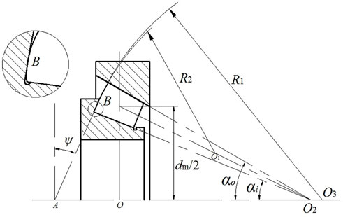
FIGURE 1. Schematic diagram of the tapered roller bearing.
In this analysis, parameters of a double-row tapered roller bearing used in railway coaches (Hu et al., 2013) are as follows: αi = 11.11°, αo = 15.11°, the diameter for the large end of the roller Dmax = 17.56 mm, the diameter for the small end of the roller Dmin = 16.15 mm, the length of the roller l = 18.97 mm, and the pitch diameter dm = 155 mm.
When the tapered roller bearing is running, pure roll exists between the roller and the race. The outer race is stationary, and the inner race rotates with angular speed ωi, assuming that the direction of the angular speed is positive. According to the kinetic principle and the structure analysis of tapered roller bearings, the rotational speed ωb and revolution speed ωc (Jiang et al., 1994) are given, respectively, as follows:
Note that the minus sign in Eq. 1 denotes the opposite direction of ωb to that of the angular speed of the inner race ωi,
The spinning speed of the roller relative to the inner race is
where α is the angle between the direction of the spinning speed and the center axis of the roller, and β is the half conical angle, i.e., β = 0.5 (αo−αi).
Defining hc as the contact height from the nominal contact point B to the inner raceway, the velocity of the rib of the inner race in the contact region is written as
The velocity of the large end of the tapered roller in the contact area is
Velocity analysis shown in Figure 2 defines that
where u1 and v1 are velocities of the rib in the direction of x and y, respectively; u2 and v2 are velocities of the roller in the direction of x and y, respectively.

FIGURE 2. Analysis of velocity.
The entrainment velocities uR and vR in the direction of x and y are
2.2 Structures of the rib
2.2.1 Spherical rib
To guarantee the wedge gap and surface tangent between the rib face and the roller end, the relationship of R1 > R > R2 should be satisfied in tapered roller bearings.
Provided that the curvature radii of the rib on vertical and axial planes are Rx1 and Ry1 and curvature radii of the roller end on vertical and axial planes are Rx2 and Ry2, respectively, then Rx1 = Ry1 and Rx2 = Ry2 are suitable for the spherical rib and spherical roller end.
The contact height hc (Zhang et al., 1988) between the nominal contact point B and the inner raceway can be written as follows:
If β is small, then
From Figure 1, the following relationship can be obtained:
2.2.2 Tapered rib
Different from the spherical rib, the generatrix of the tapered rib is a straight line on the axial plane; therefore, the curvature radius on the axial plane is Ry1 = ∞. Rx2 = Ry2 and Rx1 > Rx2 are still satisfied. Eqs. 8, 9, and 10 are also suitable for the tapered rib and spherical roller end.
3 Mathematical model
3.1 Rheological model
The Carreau rheological model is used, and its constitutive equation (Yasuda et al., 1981; Maccioni et al., 2022) is as follows:
where η* is the effective viscosity of the non-Newtonian fluid. G is the shear modulus, and it is the demarcation point between the Newtonian fluid and Carreau–Yasuda fluid. n is the power exponent, and it can be obtained by the experiment or the non-equilibrium molecular dynamics simulation.
3.2 Reynolds equation
The Reynolds equation is simplified from the generalized Reynolds equation proposed by Yang and Wen (1990).
where p is the film pressure and h is the film thickness.
The boundary conditions of Eq. 12 are
3.3 Temperature control equations
Thermal convection can be neglected as the entraining speed is not very high in spinning EHL. The temperature equation for the oil film is simplified as
where ρ is the density of the lubricant, k is the thermal conductivity of the lubricant, t is the temperature, and u, v are the flow velocities in the direction of x and y, respectively.
The equation of thermal conduction for moving Solid 1 is
where c1, ρ1, k1, and z1 are the specific heat, the density, the thermal conductivity, and the coordinate of Solid 1, respectively.
The equation of thermal conduction for stationary Solid 2 can be written using the Laplace equation as follows:
where z2 is the coordinate for Solid 2.
Different from the previous model, Solid 2 is assumed as a half-infinitely large solid, and the surface temperature can be derived from Eq. 16, i.e.,
where t0 is the environmental temperature and k2 is the thermal conductivity of Solid 2.
3.4 Film thickness equation
The film thickness equation between the roller and the rib can be expressed as
where Ω is the computing domain and Rx and Ry are equivalent curvature radii along the x and y direction, respectively.
3.5 Density–pressure–temperature relationship
If the Tait state equation (Liu et al., 2006) is amended by the thermally modified function, then the relationship of density–pressure–temperature is described as
where ρ0 and V0 are the density and volume of the lubricant at the atmospheric pressure. V is the volume of the lubricant at pressure p. K0 and K′0 are constants, which are determined by the experiment. C is the coefficient of thermal expansion, and C = 0.0008 K−1 is used in the analysis.
3.6 Viscosity equation
The viscosity of the lubricant is calculated by the Doolittle equation. Because the Doolittle equation is solved with the density equation, if the density equation under thermal conditions is substituted into the viscosity equation, the viscosity–temperature relationship of the lubricant can be expressed as (Liu et al., 2006)
where Vocc/V0 and B are unknown constants, and V/V0 is determined using Eq. 19.
4 Numerical method
In tapered roller bearings, the position of the nominal contact point or the curvature radius of the rib and the roller large end can be determined by the optimal design. Based on αi, αo, β, and Ri of the bearing, if hc/R and R2/R1 are given, R1, R2, and ψ will be obtained by solving Eqs. 8, 9, and Eq. 10. The numerical methods such as the secant method (Zhang et al., 1988) are used to solve the problem in this article. The details are as follows.
Define the residual error a as follows:
where
where φ = ψ−αi.
The secant method is employed, and the range of φ is defined as
The iteration will stop after |a| < ε, and ε is set at 0.0001 to ensure accuracy. φ and R2/R are output at last. R1 and R2 can be obtained by calculating R1/R = (R2/R)/(R2/R1).
After R1, R2, and ψ are computed, the equivalent curvature radii Ry and Rx can be obtained for the two kinds of rib structures. The numerical calculation for TEHL is carried out based on the dimensionless form. Different from the previous model, the film pressure is obtained with the multi-grid method (Venner et al., 1990), the elastic deformation is computed with the multi-level multi-integration method (Brandt and Lubrecht, 1990), and the temperature field is calculated with the column-by-column technique (Qu et al., 2000). Five levels are used, and the node number is 257 and 257 along the X- and Y-direction, respectively, at the finest level. A total of 16 layers are arranged in the Z-direction, of which 10 layers are arranged across the film and six layers are arranged for moving Solid 1. The temperature of stationary Solid 2 is calculated with the multi-level multi-integration method. The convergence criterion is that the relative error is less than 1 × 10⁻⁴ for the pressure and temperature, and the relative error is less than 1 × 10⁻³ for the load.
5 Results and discussion
Squalane oil with a low pour point is selected as the lubricant, and its parameters are shown in Table 1. The shear modulus G = 6 MPa, and the power exponent n = 0.42 for the Carreau model. The nominal contact height hc = 4 mm.
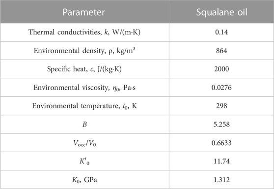
TABLE 1. Parameters of the lubricant.
5.1 Typical solutions
Surface plots of the film thickness, the pressure, and the mid-layer film temperature for the spherical rib are shown in Figure 3 for Rx2/Rx1 = 0.3, w = 320 N and ni = 1,000 r/min. From Figures 3A, B, it can be found that typical characteristics of EHL are exhibited by the spherical rib, i.e., the exit constriction of the film thickness and the second spikes for the pressure distributions. Moreover, the surface plots of the film temperature in Figure 3C are similar to those of the pressure.
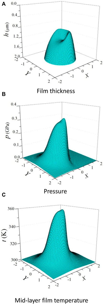
FIGURE 3. Typical numerical solutions for the spherical rib for Rx2/Rx1 = 0.3, w = 320 N, and ni = 1,000 r/min. (A) Film thickness, (B) pressure, and (C) mid-layer film temperature.
With the same input parameters as in Figure 3, the surface plots of the film thickness, the pressure, and the mid-layer film temperature are shown in Figure 4 for the tapered rib. It can be seen that the characteristics of EHL for the tapered rib are weaker than those for the spherical rib. This is because the contact region is so large that the maximum pressure is small with the same load, and it contributes less to the elastic deformation. Compared to the spherical rib, the film temperature is lower than that for the tapered rib. Hence, the film thickness for the tapered rib is larger. It can be observed that the spinning motion has little influence on the film thickness, the pressure, and the temperature for the two rib structures in the present analysis. The reason is that the maximum film temperature occurs near the center of the contact region, which is similar to that of the maximum pressure, and illustrates the primary effect of pressure on the temperature. Therefore, the contribution of the spinning velocity is small near the contact center, and the effects of spinning on the maximum temperature are minimal.
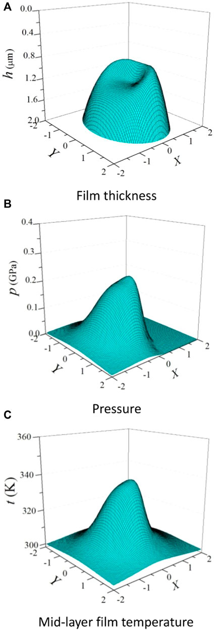
FIGURE 4. Typical numerical solutions for the tapered rib for Rx2/Rx1 = 0.3, w = 320 N, and ni = 1,000 r/min. (A) Film thickness, (B) pressure, and (C) mid-layer film temperature.
5.2 Effects of rotational speed
Figure 5 shows variations in the frictional coefficient versus the ratio of the curvature radius of the roller large end to that of the rib with various rotational speeds for the two rib structures for w = 560 N. It can be found that the variation tendency of the frictional coefficient is similar for the two types of ribs, i.e., decreasing at first and then increasing with the ratio of the curvature radius of the roller large end to that of the rib. Therefore, there exists an optimal ratio of the curvature radius. For the three rotational speeds, the optimal ratio of the curvature radius is 0.75 for the spherical rib. However, the optimal ratio with three speeds is 0.55, 0.5, and 0.45, respectively, for the tapered rib. Hence, the ratio for the tapered rib/spherical roller Rx2/Rx1 ranges from 0.45 to 0.55 to obtain the least frictional coefficient. When the ratio approaches unity for the tapered rib, the frictional coefficient increases remarkably, and the reason is that the film breakdown occurs due to the lack of wedge effect. In addition, effects of Rx2/Rx1 on the frictional coefficient for the spherical rib are less sensitive than those for the tapered rib. Different from the tapered rib, the frictional coefficient for the spherical rib is always low with the increase in Rx2/Rx1. This is because the Hertzian contact region is circular for the spherical rib/spherical roller large end, whereas it is elliptical for the tapered rib/spherical roller large end which produces lower maximum pressure and film temperature.
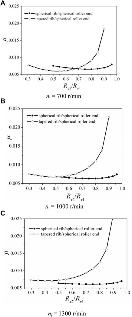
FIGURE 5. Variations in the frictional coefficient versus Rx2/Rx1 with various rotation speeds for w = 560 N. (A) ni = 700 r/min, (B) ni = 1,000 r/min, and (C) ni = 1,300 r/min.
It can be concluded that the optimal ratio of the curvature radius is determined by the rotational speed for the tapered rib, so it can be adjusted according to the bearing speed when the tapered rib is designed. Additionally, it can be observed that when the speed is low, the difference in the frictional coefficient is small corresponding to the optimal ratio of the curvature radii for the two ribs, whereas when the speed is high, the frictional coefficient for the spherical rib is less than that for the tapered rib corresponding to the optimal ratio of the curvature radii. This can evidently be attributed to the reduction of viscosity caused by thermal effects under higher speed conditions. Additionally, the maximum film temperature for the spherical rib is higher than that for the tapered rib.
Effects of the rotational speed of the inner race on the film thickness and temperature for the two ribs are shown in Figure 6 for Rx2/Rx1 = 0.7 and w = 320 N; Figure 6A represents the spherical rib, and Figure 6B represents the tapered rib. As the rotational speed increases, both the minimum film thickness and central film thickness increase for the two ribs. This clearly demonstrates the dominant effect of speed on the film thickness in EHL. In addition, for the spherical rib, the difference between the central and minimum film thickness increases with the increasing speed. However, the difference is almost unchangeable for the tapered rib. The reason is that, compared to the tapered rib, the temperature of the film and the roller large end rises obviously for the spherical rib, and thermal effects cause an obvious reduction in film thickness. Moreover, due to the sliding effect, the highest temperature of the film and the roller large end increases with the increasing rotational speed, but the rib temperature changes negligibly. This is because the rib is running more quickly than the roller, and the heat transfer from the film to the rib is difficult. Therefore, when the ratio of the curvature radius and load are fixed, the minimum film thickness is larger for the tapered rib. The optimal lubricating performance is determined by the dealing of the frictional coefficient and the film thickness.
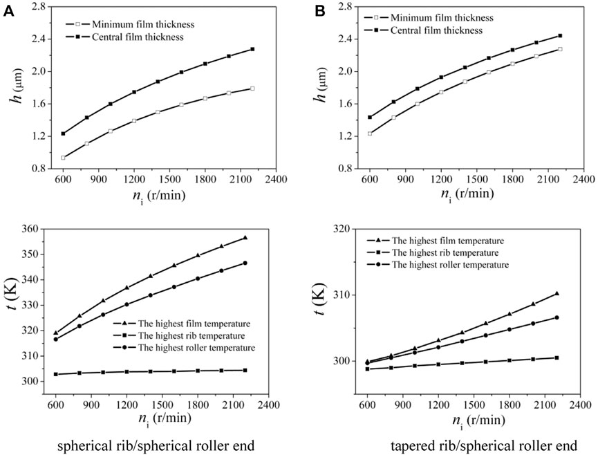
FIGURE 6. Effect of rotating speeds on film thickness and temperature of two rib structures for Rx2/Rx1 = 0.7 and w = 320 N. (A) Spherical rib/spherical roller end; (B) tapered rib/spherical roller end.
5.3 Effects of the load
When ni = 1,000 r/min, variations in the frictional coefficient versus the ratio of curvature radius of the roller large end to that of the rib with various loads for the two ribs are seen, as shown in Figure 7. It can be observed that the frictional coefficient decreases first and then increases with the ratio of curvature radius when the load is different, and the difference between the two types of rib becomes large when the load increases. This is because the position of the nominal contact point changes with the ratio of curvature radius for the tapered rib/spherical roller. Moreover, large load will lead to high temperature and thus lower viscosity of the lubricant and low frictional coefficient. With the increase in the load, the optimal ratio of the curvature radius is always 0.75 for the spherical rib, while the optimal ratio for the tapered rib is 0.35, 0.45, and 0.5, respectively. Therefore, the optimal ratio of the curvature radius is determined by both the load and the velocity for the tapered rib. However, the optimal ratio is hardly influenced by the velocity and the load for the spherical rib. This can be attributed to the characteristics of the spherical rib/spherical roller end, and thermal effects on the frictional coefficient are more significant than those for the tapered rib/spherical roller end.
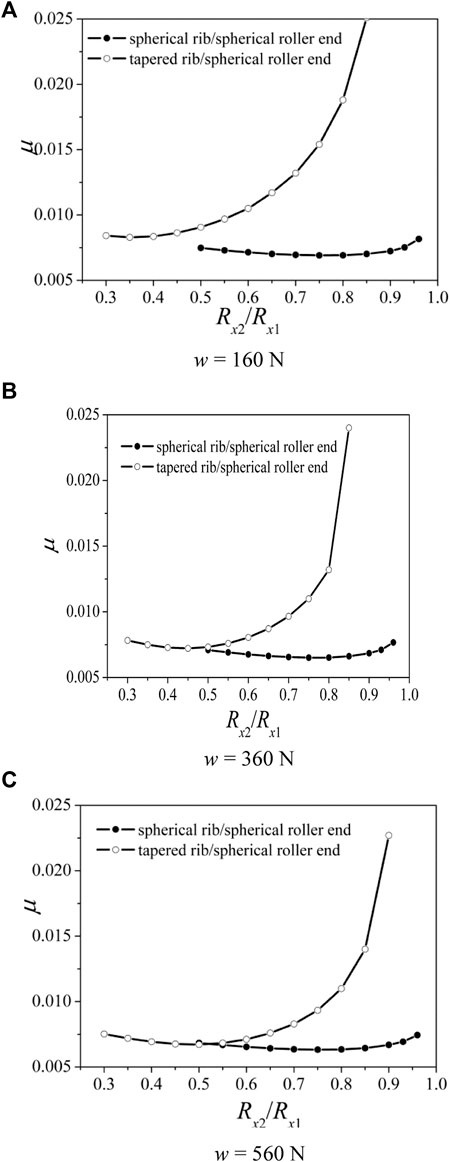
FIGURE 7. Variations in the friction coefficient versus Rx2/Rx1 with different loads for ni = 1,000 r/min. (A) w = 160 N, (B) w = 360 N, and (C) w = 560 N.
Figure 8 shows effects of the load on the film thickness and temperature for the two rib structures for Rx2/Rx1 = 0.7 and ni = 1,000 r/min; Figure 8A represents the spherical rib, and Figure 8B represents the tapered rib. It can be found that the spherical rib is much more sensitive to the load, and the film thickness varies more widely than that for the tapered rib. In addition, the minimum film thickness decreases remarkably, and the central film thickness increases first and then decreases slightly with the increase in the load. This is because the central film thickness is the function of the load. The central film thickness decreases slightly as the load surpasses a value. This is coherent with the film thickness formula proposed by Hamrock and Downson. Moreover, the minimum film thickness decreases because of the high pressure and temperature in the contact region with large load. However, with the increase in the load, the central film thickness increases for the tapered rib. There may be two reasons: one is that the thermal expansion caused by the film temperature rises in the contact region; the other is that the special contact between the rib and the roller end leads to the low pressure and small elastic deformation in the contact region, resulting in weak thermal effects. As the load increases, the central elastic deformation and film thickness increase to balance the uneven distribution of the pressure. It can be concluded that variations in the central film thickness versus the load are abnormal for the tapered rib/spherical roller end (Jiang et al., 1994).
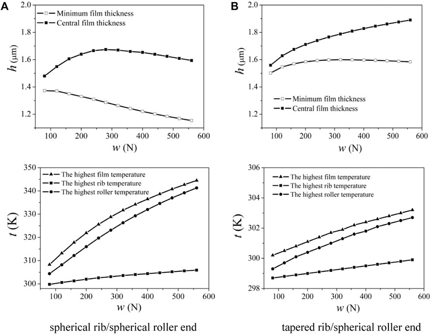
FIGURE 8. Effects of load on film thickness and temperature of two rib structures for Rx2/Rx1 = 0.7 and ni = 1,000 r/min. (A) Spherical rib/spherical roller end; (B) tapered rib/spherical roller end.
It can be seen from the temperature profiles that, as the load increases, for the spherical rib, higher temperature for the film and the roller will be generated because the contact between the rib and the roller end prevents the heat loss. However, the rib temperature increases insignificantly due to high rotational speed and slow heat transfer. Different from the spherical rib, there is a little change in temperature for the film, the rib, and the roller for the tapered rib–roller contact. Therefore, to improve the lubricating performance, the decisive effects on the minimum film thickness are the rib structures, followed by the speed and the load.
Conclusion
Based on the structure analysis for the rib of the inner race and the large end of the roller in tapered roller bearings, a thermal EHL model considering spin–slide effects is established with Carreau fluid. The main conclusions are as follows:
1. Effects of spinning motion on the lubricating performance are minimal between the rib of the inner race and the large end of the tapered roller.
2. The optimal ratio of the curvature radius of the roller large end to that of the rib exists both for the tapered rib and the spherical rib, and the frictional coefficient corresponds the least to the optimal ratio. Moreover, the optimal ratio changes with the rotational speed and the load for the tapered rib. Different from the tapered rib, the frictional coefficient is low for the spherical rib with the increase in Rx2/Rx1.
3. With the increase in the rotational speed of the inner race, the film thickness and the temperature increase for the two rib structures. Different from the spherical rib, the difference between the minimum and the central film thickness is nearly unchangeable, and the minimum film thickness is larger due to low film temperature rise for the tapered rib.
4. With the increase in the load, the difference between the minimum and central film thickness becomes large for the two rib structures, and the film temperature rises. Compared to the tapered rib, variation in the temperature is significant, and the minimum film thickness is lower for the spherical rib.
5. Further study on this problem is needed for practical engineering.
Data availability statement
The original contributions presented in the study are included in the article/Supplementary Material;, further inquiries can be directed to the corresponding author.
Author contributions
XLiu and TL carried out the theoretical analysis. XLiu wrote the manuscript with support from XLi. FG and XLiu conceived the original idea and supervised the project.
Funding
This work was supported financially by the National Natural Science Foundation of People’s Republic of China (grant no. 52275196 and 51475250) and the “Taishan Scholar” Talents Project from Shandong Province (No. TS20190943).
Conflict of interest
The authors declare that the research was conducted in the absence of any commercial or financial relationships that could be construed as a potential conflict of interest.
Publisher’s note
All claims expressed in this article are solely those of the authors and do not necessarily represent those of their affiliated organizations, or those of the publisher, the editors, and the reviewers. Any product that may be evaluated in this article, or claim that may be made by its manufacturer, is not guaranteed or endorsed by the publisher.
References
Bair, S. (2004). A rough shear thinning correction for EHL film thickness. STLE Tribol. Trans. 47 (3), 361–365.
Bair, S., and Khonsari, M. M. (2006). Reynolds equations for common generalized Newtonian models and an approximate Reynolds-Carreau equation. Proc. Instn. Mech. Engrs, Part J, J. Eng. Tribol. 220, 365–374. doi:10.1243/13506501jet79
Bair, S. (2009). Rheology and high-pressure models for quantitative elastohydrodynamics. Proc. Instn. Mech. Engrs, Part J, J. Eng. Tribol. 223, 617–628. doi:10.1243/13506501jet506
Brandt, A., and Lubrecht, A. A. (1990). Multilevel matrix multiplication and fast solution of integral equations. J. Comput. Phys. 90, 494. doi:10.1016/0021-9991(90)90264-2
Carreau, P. J. (1972). Rheological equations from molecular network theories. Trans. Soc. Rheology 16 (1), 99–127. doi:10.1122/1.549276
Gadallah, N., and Dalmaz, G. (1984). Hydrodynamic lubrication of the rib-roller end contact of a tapered roller bearing. ASME J. Tribol. 106, 265–272. doi:10.1115/1.3260898
Gao, P., Tang, W., Cui, Y., Wang, Y., Mo, G., and Yin, J. (2022). Theoretical and experimental investigation on thermal characteristics of railway double-row tapered roller bearing. Energies 15, 4217. doi:10.3390/en15124217
Harris, T. A., and Kotzalas, M. N. (2009). Rolling bearing analysis FIFTH EDITION: Essential concepts of bearing Technology. Beijing: Mechanical Industry Press.
Hu, L., Wang, W. Z., Zhao, Z. Q., and Kong, L. J. (2013). Lubricated contact analysis of roller large end flange in double row tapered roller bearing. Tribology 33 (1), 22∼28. (in Chinese).
Jamison, W. E., Kauzlarich, J. J., and Mochel, E. V. (1976). Geometric effect on the rib-roller contact in tapered roller bearing. ASLE Trans. 20, 79–88.
Jiang, X. F., Wong, P. L., and Hong, Y. (1994). Thermal non-Newtonian EHL analysis of rib-roller end contact in tapered roller bearing. Hawaii, USA October: ASME/STLE annual conference.
Katyal, P., and Kumar, P. (2012). Central film thickness formula for shear thinning lubricants in EHL point contacts under pure rolling. Tribol. Int. 48, 113–121. doi:10.1016/j.triboint.2011.11.007
Kumar, P., and Khonsari, M. M. (2009). On the role of lubricant rheology and piezo-viscous properties in line and point contact EHL. Tribol. Int. 42, 1522–1530. doi:10.1016/j.triboint.2008.11.006
Kumar, P., and Kumar, N. (2014). Surface roughness effects in pure sliding EHL line contacts with carreau-type shear-thinning lubricants. Int. J. Mech. Aerosp. Industrial Mechatronics Eng. 8, 1104–1109.
Liu, Y. C., Wang, J., Bair, S., and Vergne, P. (2007). A quantitative solution for the full shear-thinning EHL point contact problem including traction. Tribol. Lett. 28 (2), 171–181. doi:10.1007/s11249-007-9262-5
Liu, Y., Kang, W., Zhu, Y., Yan, K., and Hong, J. (2020). Effects of defect on roller-raceway contact state and friction torque of tapered roller bearings. ASME J. Tribol. 142, 111501. doi:10.1115/1.4047194
Liu, Y., Wang, Q. J., Wang, W., Hu, Y., Zhu, D., Krupka, I., et al. (2006). EHL simulation using the free-volume viscosity model. Tribol. Lett. 23 (1), 27–37. doi:10.1007/s11249-006-9101-0
Maccioni, L., Chernoray, V. G., Mastrone, M. N., Bohnert, C., and Concli, F. (2022). Study of the impact of aeration on the lubricant behavior in a tapered roller bearing: Innovative numerical modelling and validation via particle image velocimetry. Tribol. Int. 165, 107301. doi:10.1016/j.triboint.2021.107301
Majdoub, F., Saunier, L., Sidoroff-Coicaud, C., and Mevel, B. (2020). Experimental and numerical roller skew in tapered roller bearings. Tribol. Int. 145, 106142.
Qu, S., Yang, P., and Guo, F. (2000). Theoretical investigation on the dimple occurrence in the thermal EHL of simple sliding steel-glass circular contacts. Tribol. Int. 33 (1), 59–65. doi:10.1016/s0301-679x(00)00031-1
Tian, Y. B., Li, L. G., Han, J. G., Fan, Z. H., and Liu, K. (2021). Development of novel high-shear and low-pressure grinding tool with flexible composite. Mater Manuf. Process 36 (4), 479–487. doi:10.1080/10426914.2020.1843673
Tian, Y. B., Li, L. G., Fan, S., Guo, Q. J., and Cheng, X. (2021). A novel high-shear and low-pressure grinding method using specially developed abrasive tools. P I Mech. Eng. B-J Eng. 235 (1-2), 166–172. doi:10.1177/0954405420949106
Venner, C. H., ten Napel, W. E., and Bosma, R. (1990). Advanced multilevel solution of the EHL line contact problem. ASME J. Tribol. 112, 426–431. doi:10.1115/1.2920277
Wirsching, S., Marian, M., Bartz, M., Stahl, T., and Wartzack, S. (2021). Geometrical optimization of the EHL roller face/rib contact for energy efficiency in tapered roller bearings. Lubricants 9, 67. doi:10.3390/lubricants9070067
Wu, Z., Xu, Y., and Liu, K. (2020). Study on logarithmic crowning of tapered roller profile considering angular misalignment. ASME J. Tribol. 142, 111201. doi:10.1115/1.4047106
Yang, P., and Wen, S. (1990). A generalized Reynolds equation for non-Newtonian thermal elastohydrodynamic lubrication. ASME J. Tribol. 112, 631–636. doi:10.1115/1.2920308
Yasuda, K. Y., Armstrong, R. C., and Cohen, R. E. (1981). Shear flow properties of concentrated solutions of linear and star branched polystyrenes. Rheol. Acta 20 (2), 163–178. doi:10.1007/bf01513059
Yasuda, K. Y. (1979). Investigation of the analogies between viscometric and linear viscoelastic properties of polysyrene fluids. Cambiridge, MA: Ph.D thesis, MIT.
Keywords: tapered roller bearing, Carreau model, inner rib structures, roller end, thermal EHL
Citation: Liu X, Long T, Li X and Guo F (2023) Thermal EHL analysis of the inner ring rib and roller end in tapered roller bearings with the Carreau model. Front. Manuf. Technol. 2:1029860. doi: 10.3389/fmtec.2022.1029860
Received: 28 August 2022; Accepted: 16 December 2022;
Published: 10 January 2023.
Edited by:
Yebing Tian, Shandong University of Technology, ChinaReviewed by:
Aqib Mashood Khan, Nanjing University of Aeronautics and Astronautics, ChinaLixiao Wu, Lanzhou University of Technology, China
Van-Canh Tong, Samsung Display Vietnam, Vietnam
Bing Liu, Shandong University of Technology, China
Copyright © 2023 Liu, Long, Li and Guo. This is an open-access article distributed under the terms of the Creative Commons Attribution License (CC BY). The use, distribution or reproduction in other forums is permitted, provided the original author(s) and the copyright owner(s) are credited and that the original publication in this journal is cited, in accordance with accepted academic practice. No use, distribution or reproduction is permitted which does not comply with these terms.
*Correspondence: Xiaoling Liu, liu_xiaoling06@126.com