Prediction of fatigue life of geometrically deviated steam turbine blades under thermo-mechanical conditions
 Makgwantsha Hermelton Mashiachidi
 Dawood A. Desai
- Department of Mechanical and Mechatronics Engineering, Tshwane University of Technology, Pretoria, South Africa
This study explores the intricate factors affecting the fatigue life of steam turbine blades, encompassing steam flow-induced bending, centrifugal loading, vibration response, structural mistuning, and temperature-dependent influences. By focusing on the significance of mistuned steam turbine blades with varying blade geometries due to manufacturing tolerances, this research has paramount relevance for the power generation industries. By employing finite element analysis (FEA) software, a simplified, mistuned, scaled-down steam turbine bladed disk model was developed, considering temperature-dependent material properties. Initial FEA provided insights into the vibration characteristics and steady-state stress responses, with numerical stress distributions evaluated, which were subsequently exported to Fe-Safe software for fatigue life calculations based on centrifugal and harmonic sinusoidal pressure loadings. By investigating the vibration characteristics and response to geometric blade variations, this study affirmed the reliability of the developed FEA model, with findings highlighting the pronounced sensitivity of fatigue life to blade length, width, and thickness variations, in this order. However, in order to validate the developed numerical models, analytical life cycle assessments were calculated, which exhibited a discrepancy of under 3.37%, reinforcing the applicability of the developed numerical methodology to real-world scenarios involving mistuned steam turbine blades experiencing manufacturing deviations in blade geometry.
1 Introduction
Steam turbine blades play a vital role in power plants, as they are essential components responsible for converting the linear movement of high-temperature, high-pressure steam, which flows along a pressure gradient, into a rotary motion of the turbine shaft (Mukhopadhay et al., 1998).
Fatigue failures of steam turbine blades have been a persistent issue in numerous power plants. It is well-established that turbine blade failures and damage are the primary factors contributing to the unavailability of large fossil fuel turbines globally (McCloskey et al., 1999; Booysen et al., 2015). Any disruption in the operation of a steam turbine, such as the failure of a blade, can lead to substantial monetary losses (McCloskey et al., 1999; Booysen et al., 2015). Fatigue damage in the engineering industry has cost several percentages of the gross domestic product. Prediction of the life of steam turbine blades subjected to varying blade geometries attached to a common disk is a great benefit in fossil fuel power plants (Booysen et al., 2015). While the turbine is in operation, the blades experience bending due to high-pressure flows, endure centrifugal stresses, and respond to significant vibrations caused by alternating stress conditions (Mashiachidi and Desai, 2023).
Blade failures have been documented to occur through various mechanisms, including corrosion, low cycle fatigue (LCF), high cycle fatigue (HCF), and erosion (Das et al., 2003; Kubiak Sz et al., 2007). Furthermore, a significant concern regarding steam turbine blades lies in the emergence of cracks at the blade’s root region due to stress concentration and improper interaction between the blade root and rotor fastening areas during turbine operation, ultimately leading to blade failures (Kubiak Sz et al., 2009). Throughout the turbine’s service life, blades are constantly exposed to excitation forces under standard operational conditions, including centrifugal forces, torsion, and bending from steam forces. Notably, the loads resulting from centrifugal forces surpass the magnitudes of other steam-induced torsion and bending forces. Steam turbine bladed disks are initially designed to exhibit cyclical symmetry, but inherent factors such as manufacturing tolerances, material non-uniformity, and wear during operation can affect this symmetry (Rieger, 1988).
Fatigue is the phenomenon where damage accumulates over time as a result of cyclic stresses. Fatigue is recognized as a primary damage mechanism that leads to substantial losses. Turbine blade fatigue can be categorized into either HCF or LCF. LCF is usually associated with fewer load cycles with a much larger strain range, corrosion, or high temperature (Santecchia et al., 2016). HCF is commonly associated with moderate mean stress levels and high dynamic stresses.
This research presents a probabilistic approach for evaluating the HCF behavior of mistuned steam turbine blades, accounting for variations in blade geometry. The blade model was developed using 3D ABAQUS software by employing the finite element (FE) method to create a numerical model that encompasses all geometric variations of the blade. Predicting the fatigue life of mistuned steam turbine blades is a complex task due to various uncertain factors, including material fatigue properties, excitation force magnitude, dimensions, stress states, and vibration responses. Hence, selecting appropriate material properties, elastic modulus, and density to ensure alignment with the experimental object is of paramount importance.
The 304 stainless steel is favored for its wide application, especially in blades subject to significant centrifugal and bending loads within steam turbines. Its remarkable ductility allows for nuanced plastic deformation at the root contact, preventing failures and cracks, as seen in Schönleitner et al. (2015). This material is chosen for its tailored characteristics that address steam turbine blade challenges, and this paper thoroughly examines the behavior of the material in the context of steam turbine applications.
The martensitic stainless steel X22CrMoV12-1 (DIN 1.4923), chosen for characterizing the LP blades, is commonly used in Eskom power stations due to its exceptional strength and corrosion resistance, making it suitable for the demanding conditions in steam turbines, as noted by Booysen et al. (2015). It is worth mentioning that while it is not the focus of the current investigation, this material is a modified version of the high-temperature grade steel X20CrMoV12-1 that had found extensive use in steam power plants in the early 1960 s. This information offers insights into an alternative material that may warrant consideration for future studies or applications.
The FEM of a simplified and scaled-down free-standing LP steam turbine blade of the 304 stainless steel is used to measure the vibration characteristics and stress state of the blade. Model analysis is used to characterize the natural frequencies of the blade model. Natural frequencies of the model are validated using the literature.
Limited research exists on mistuned steam turbine blades resulting from variations in blade geometry. This study provides a unique contribution by addressing the methodology for predicting the life of mistuned steam turbine blades, specifically considering the impact of geometric blade variations. The use of a probabilistic approach to predict the fatigue life of a realistic mistuned blade model has not been extensively explored, and there is potential to develop a reliable methodology by integrating these concepts. Precise investigation is required as this approach has not been thoroughly studied. The study uses the Brown–Miller algorithm in Fe-Safe software, and the results are expected to have a positive impact on power plant safety, stability, efficiency, availability, and financial performance.
2 Review of the literature/related studies
2.1 High cycle fatigue
HCF refers to fatigue life cycles spanning from
Rao and Saldanha (2003) observed that the blades undergo vibration and resonate at critical speeds, leading to the generation of high dynamic stresses and, consequently, the accumulation of HCF damage. In a separate investigation by Henry et al. (1998) focusing on steam turbine resonance, it was confirmed that when a steam turbine is in resonance, it initiates the formation of fatigue cracks.
Henry et al. (1998) deduced that the vibratory stresses induced in the blade during resonance modes exceed the fatigue strength of the blade material. Rao and Vyas (1996) pointed out that dynamic stresses are influenced by factors such as the source and magnitude of excitation, damping within the blade, and the degree of mistuning in steam turbine blade geometries.
2.2 Blade fatigue life prediction
The research outlined in Liu and Mahadevan (2005) introduced a framework proposing a multiaxial HCF criterion based on the critical plane. Diverging from many existing multiaxial fatigue criteria using the critical plane approach, this criterion directly correlates with the fatigue fracture plane. The study demonstrated its broad applicability across various materials, ranging from highly ductile to extremely brittle metals, and considered the mean stress effect. Subsequently, the researchers extended this multiaxial fatigue criterion to formulate a fatigue life prediction model, validated with experimental results from recent literature.
Furthermore, in a separate study, Liu and Mahadevan (2007) presented a methodology for stochastic fatigue life prediction under variable amplitude loading. This methodology combines a nonlinear fatigue damage accumulation rule with a stochastic S-N curve representation technique. The nonlinear damage accumulation rule improves upon the limitations of the linear rule while maintaining simplicity in its application. It also considers the covariance structure of the stochastic damage accumulation process under variable amplitude loading. The authors validated this methodology using existing literature and compared it with current fatigue models.
Simmons and Allison (2010) devised a practical approach for approximating cyclic stresses in rotating blades. Their method relies on impulse testing with strain gauge sensors and simplified aerodynamic excitations. This approach has been successfully employed to identify the root causes of blade and impeller failures in gas turbines, steam turbines, and industrial compressors. It provides guidance on determining the natural frequencies most responsible for fatigue failure through experimental stress in resonance analyses. The authors incorporate the Campbell diagram to assess frequency margins and use the Goodman diagram method to evaluate endurance stress margins. In conclusion, this method allows for the inclusion of mistuned blade responses and the evaluation of operating cycles through the Palmgren–Miner analysis (Simmons and Allison, 2010).
Da-Yi et al. (2012) emphasized the importance of accurately predicting the fatigue behavior of steam turbine blades, particularly in assessing the number of cycles before crack initiation within stress concentration regions. Bathias and Pineau (2013) described the three phases a mistuned steam turbine blade undergoes before fatigue failure, crack initiation, slow crack propagation, and sudden propagation, leading to fracture. Booysen et al. (2015) highlighted the significance of fatigue life prediction in estimating the remaining life of steam turbine blades, ultimately facilitating improved turbomachine management, life cycle cost optimization, and overall plant safety.
Han et al. (2019) highlighted the importance of optimizing computational efficiency through a singular execution of FEA. This approach aims to establish the relationship between vibrations by strategically focusing on small structural features. The result is a significant reduction in computational time compared to simulations involving full-sized features. By prioritizing efficiency through targeted analysis, this methodology demonstrates its effectiveness in obtaining precise results while minimizing computational expenses. Hence, in this study, the total time required to perform each simulation was 150 s.
2.3 Brown Miller and Dang Van criterion validation
According to Mofoka (2018), the Dang Van criterion is a stress-based multiaxial fatigue criterion used to predict the HCF life of mechanical components. The Brown–Miller algorithm is a method primarily used for fatigue life calculation under multiaxial stress–strain conditions (eFatigue, 2017).
The von Mises criterion, although useful to predict yielding, lacks suitability for HCF analysis as it uses the von Mises equivalent stress, an unsigned quantity, while fatigue analysis requires a signed quantity. This limitation renders the von Mises criterion ineffective in HCF prediction, particularly in scenarios involving non-proportional loading (Mofoka, 2018). Consequently, it is established that the von Mises criterion has limited capabilities in calculating fatigue life compared to stress-based methods like the Dang Van multiaxial criterion and Brown–Miller analysis.
Another commonly used method is the conventional stress-based approach, known as the S-N diagram method, which defines the fatigue failure surface for mistuned steam turbine blades under specific operational conditions. However, as noted by Vyas et al. (1997), the primary drawback of this method is its inability to account for the development of a plastic strain zone. Therefore, there is a need to explore the development of blade fatigue models based on fundamental fracture mechanics concepts, which also applies to the von Mises criterion (Vyas et al., 1997).
Furthermore, the Brown–Miller and Dang Van methods remain favorable for HCF life prediction, as suggested by Winkler et al. (2012). The principal stress fatigue analysis, while a proper biaxial fatigue method, operates on the assumption that fatigue results from the amplitude of the largest principal stress, which can limit its applicability in HCF prediction compared to the Dang Van and Brown–Miller methods (Winkler et al., 2012).
As highlighted in Peridas et al. (2003), the Dang Van criterion and the Brown–Miller method address the boundary between infinite and finite life. However, other fatigue life calculation tools, such as the Goodman rule, are primarily suited for finite life prediction. To overcome this limitation, mapping extends the use of the Dang Van criterion to predict specific cyclic lives (Peridas et al., 2003).
Additionally, there is the Findley multiaxial algorithm method, which is applicable to both LCF and HCF life prediction. This method is particularly beneficial in considering the effects of minor plasticity in the material. Consequently, the stress–strain-based Brown–Miller analysis, combined with the stress-based Dang Van multiaxial fatigue method, offers accurate and less complex results (Winkler et al., 2012), hence making it a suitable choice for this paper.
In a distinctive exploration concentrating on the numerical methodology for predicting the fatigue life of mistuned steam turbines, Mashiachidi and Desai, 2023 shed light on the fact that the sensitivity of life to fatigue cycles is notably impacted by dimensions such as length, width, and thickness. Moreover, the author observed that the initiation of stress and cracks predominantly occurs at the root area of the turbine blades. Additionally, the study ensures the robustness of its findings through the validation of results, contributing valuable insights to the field of steam turbine fatigue life prediction. Heidar and Amini (2017) examined the impact of altering blade geometry on stress and strain, revealing a preference for shorter and thicker blades as a means of diminishing von Mises stress and strain when compared to their longer and thinner counterparts.
3 Analytical modeling
Creating a scaled-down model that accurately reflects both the physics and behavior is crucial for establishing the correlation between experimental and numerical outcomes. Consequently, this paper introduces the development of a scaled-down model representing a steam turbine bladed disk. The pertinent mathematical formulas and theories for scaling down the model are presented below.
3.1 Geometric similarity
Similarities in geometry necessitate that all dimensions of the actual bladed disk structure be appropriately scaled. Liu et al. (2016) emphasized that the choice of scale size for a model depends on various factors, including ease of fabrication, material availability, and frequency characteristics. In line with these considerations, Liu et al. (2016) reported that a scaling factor of approximately one-fifth of the full size of the real-world structure can be effectively used. Consequently, this paper adopts a one-fifth scale-down approach based on the aforementioned factors.
The model variables referred in this paper are constructed with dimensions (i.e., length, width, and thickness) that are 1:5 the size of the original steam turbine bladed disk. The geometric scaling factor used in this paper is N = 5, as depicted in Eqs 1–3 (Liu et al., 2016).
where
where
where
3.2 Dynamic similarity
According to Meyer (2003), dynamic similarity implies that all forces acting on the scaled model should be in proportion to those exerted on the full-scale vehicle. The ratios or scales for dynamic similarity may differ from those of geometric similarity, necessitating a distinct determination. Unlike geometric similarity, dynamic similarity is not straightforwardly stated, requiring a thorough investigation to ensure dependable and precise results.
The dynamic similarity laws that govern the behavior of scaled simplified bladed disk models in this paper were derived from Desai (2010) and are given below, with the initial one being Eq. 4.
where
where
where
3.3 Dynamic analysis
Fatigue in turbine blades is a multidisciplinary issue. The life of a blade is primarily affected by the static and dynamic stress fields acting on it, the fatigue properties of the blade material, the loading history, and the operational environment (Amroune et al., 2018). In this paper, the dynamic stress analysis is grounded in the steady-state bending stress induced by the steam. The approach involves calculating the maximum first principal stress in the area of the steam turbine blade. The steady-state bending pressure load applied on the airfoil blade is used. Damping effects are not ignored for the significance of the analysis, and the damping ratio is defined in the ABAQUS. The dynamic stress is mathematically calculated in Eq. 7 for free-standing cantilevers.
where
Considering the harmonic response analysis, sinusoidal pressure load was applied to the surface area of the blades to determine the excitation force, which was calculated using the varying function in Eq. 8.
Prior to conducting the actual dynamic stress computation, Eq. 9 is used to calculate the maximum bending moment at the blade root area.
where L is the length of the blades. The maximum bending moment and the maximum dynamic stress at the root of the blade with constant variables were calculated as 2.471 N.m and 185.30 MPa, respectively. The validation of the analytical maximum dynamic stress of 17 FEM on critical points is conducted.
3.4 Brown–Miller method
The Brown–Miller multiaxial fatigue method, created by Brown and Miller, considers both mean and alternating stresses in different directions, enhancing the accuracy of fatigue damage assessment. Applied to predict fatigue life in mistuned turbine blades, it enables researchers to grasp the impact of diverse stress conditions on structural integrity. Through the calculation of fatigue life cycles, the method assists in identifying potential failure points and optimizing design and maintenance strategies for enhanced reliability in steam turbine bladed disks.
The Brown–Miller strain-life equation gives a realistic life estimation (Booysen et al., 2015), and the life
4 Research flowchart
Figure 1 illustrates the stepwise process, outlined in a flowchart, for the FEA and FEM procedure employed in predicting the life of a simplified bladed disk. This process involves creating a scaled-down geometric model using ABAQUS software in three dimensions, generating a finite element mesh with defined element types and properties, assigning material properties considering temperature-dependent applications, specifying loading and operating conditions, and configuring analysis parameters such as time steps. Subsequently, FEA is performed to calculate frequencies and stresses, which are then validated against literature data. The model is then imported into Fe-Safe as an .obd file, using the calculated stresses for fatigue life predictions, and the predicted fatigue life cycles are analytically validated.
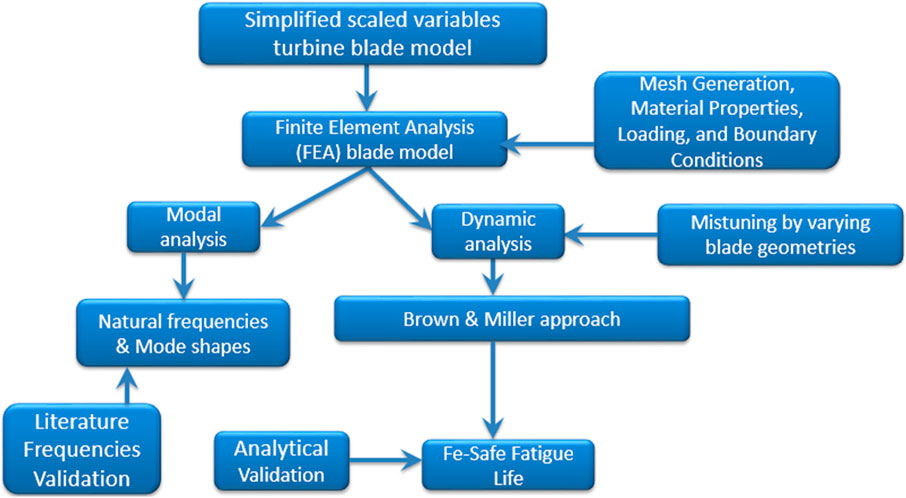
FIGURE 1. Flowchart of the research paper.
5 Numerical modeling
5.1 Development of geometric models
ABAQUS FEA software was used to create a scaled-down model consisting of eight simplified cantilever blades for an LP steam turbine, aligning with the experimental model. The primary objective of this numerical model is to examine the impact of a 5% accepted manufacturing scatter in blade geometry on the HCF life of mistuned steam turbine blades. Figure 2 depicts the two-dimensional representation of the scaled-down and simplified model featuring an 8-bladed disk. The measurements are in millimeter, and the model incorporates 5-mm fillets to alleviate the pronounced stress concentration at the blade root area.
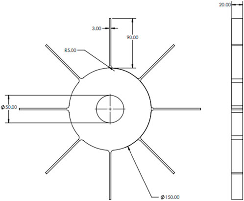
FIGURE 2. 2-dimensional steam turbine bladed disk model.
Figure 2 shows the geometric dimension, properties of the model, and boundary conditions applied in the structural analysis in ABAQUS. The length (Y) 90 mm is axially from the disk surface, thickness (Z) 20 mm is the entire bladed disk size view, and width (X) 3 mm is for each blade as illustrated in Figure 2 and the axes in Figure 13.
5.2 Blade material
304 stainless steel was used as the blade material to correspond to the experimental model obtained from Laibi and Shather (2020) and Ocaña et al. (2015). Table 1 represents the data of the material.
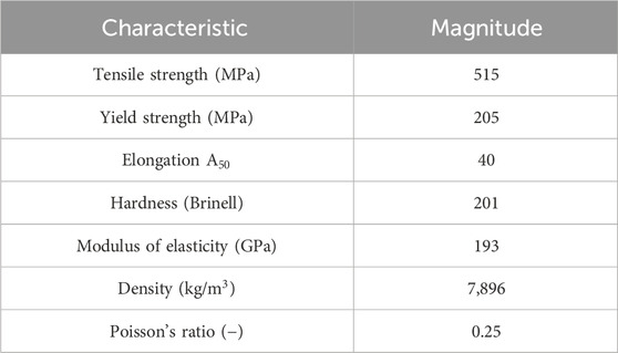
TABLE 1. Mechanical properties of 304 stainless steel at 22
5.3 Finite element mesh selection
The creation of a mesh holds crucial significance in simulation studies, influencing both the calculation time of the FE model and the precision of FEA outcomes. The selection of the mesh size was aimed at enhancing FE results. Initially, the default 4-mm mesh size yielded unsatisfactory outcomes, prompting refinement to a size of 2 mm, which still exhibited slight inaccuracies. Subsequently, mesh sizes of 1 mm and 0.5 mm were used, both yielding satisfactory results. However, it is important to note that the 0.5-mm mesh size simulation required an extended period to complete. Mesh sizes below 1 mm were not applied due to associated computational costs and time implications. The use of the C3D8R element type throughout the study aimed to improve bending ability and eliminate parasitic shear effects during blade bending.
In this study, the model underwent meshing using continuum, three-dimensional, first-order reduced integration brick element type (C3D8R), featuring homogeneous mass distribution. Accordingly, an optimal mesh size of 1 mm was selected for the blade roots, while the default mesh size was applied to the remaining sections of the FE model. The model comprises a total of 438,412 nodes and 411,341 elements. Among these, 408,165 are linear hexahedral C3D8R elements, and 16,145 are linear wedge C3D6 elements. Figure 3 illustrates the results of the meshed FE model.
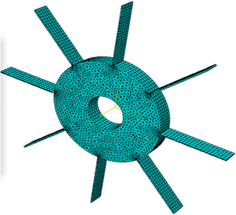
FIGURE 3. FE meshed bladed disk model.
5.4 Boundary conditions
The FE model boundary condition was initially assigned by applying the rotational constraints to the center hub surface to prevent axial movements within the simulation. Therefore, a rotational body speed of 314.159 rad/s was applied on the entire bladed-disk model that rotates around the z-direction (as shown in Figure 3) acting along the center hub (Mashiachidi and Desai, 2023; Rani and Agrawal, 2023). Figure 4 illustrates the applied rotational body forces acting in an axial direction propagating from the base state. The constraints are encastred at the blade disk center to avoid axial movement.
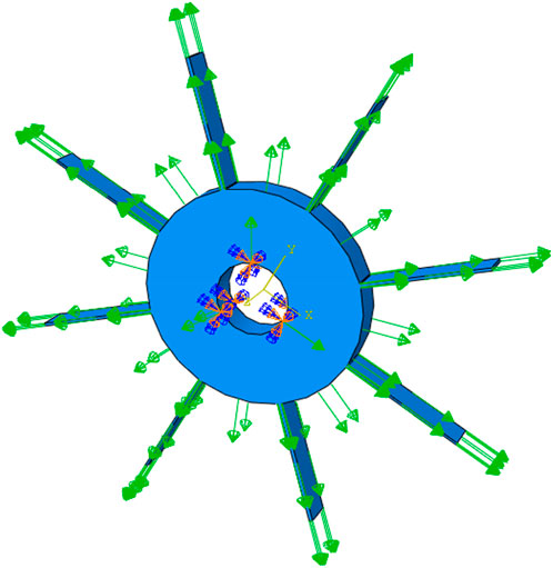
FIGURE 4. Model boundary conditions.
The boundary condition of the FEM was initially assigned by applying rotational constraints to the center hub surface to prevent axial movements within the simulation. The analysis of dynamic stress relies on the steady-state bending stress induced by the steam (Booysen et al., 2015). In our ABAQUS simulations, the dynamic explicit model is initialized with zero initial conditions. The simulation spans a time period of 0.1 s, using increments of 0.01 s, with the consideration of non-linear geometry (Nlgeom on). This choice aims to improve analysis accuracy by capturing finer details in the dynamic response of the steam turbine bladed disk. In Figure 5, the diagram depicts a constant pressure load exerted on the surfaces of the steam turbine bladed disks. Arrows indicate both the direction of the applied pressure and rotation. The stress analysis distribution was acquired in this step. The von Mises stress is equivalent to the mean stress (Das et al., 2003).
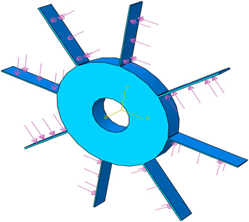
FIGURE 5. Constant pressure load on steam turbine bladed disk surface.
5.5 Natural frequencies
Eigen frequencies play a crucial role in this investigation, and as such, they were extracted through FE modal analysis. The processes given in subsections 5.1, 5.2, 5.3, and 5.4 were used in the model to replicate an experimental setup. The asymmetrical nature introduced by our eight simplified cantilever blades in a tuned steam turbine results in non-repeating natural frequencies (Mofoka, 2018).
Table 2 provides a summary of the first eight cases of natural frequencies and their corresponding operational rotation speeds obtained from the FE analysis, partially corroborated with experimental frequencies from the literature (Mofoka, 2018). Notably, the most substantial difference in natural frequencies is observed in modes 7 and 8, whereby mode 7 is only blade bending and mode 8 is blade twisting and bending. The mode shapes of the mistuned bladed disk exhibit significantly large amplitudes in a few blades, suggesting that these blades are more susceptible to fatigue failure (Mofoka, 2018). Therefore, as indicated in Table 2, modes 2 and 8 represent a combination of bending and twisting.
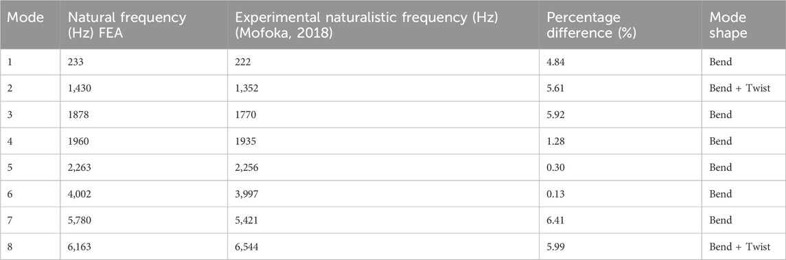
TABLE 2. Summary of the modes of natural frequency.
The amount of stress distribution in the modal simulation is used to identify the model hot spots. The arrow in Figure 11 represents the location of the initial crack. Moreover, Figure 11 confirms that the root of the cracks starts at the blade, as found in Mofoka (2018).
5.6 Mode shapes
Modal shapes, which are essential parameters in FE vibration models, visually represent deformation patterns associated with various modes of natural frequency vibration. This aids in a comprehensive understanding of the dynamics of mistuned steam turbine blades. Figure 6 illustrates a symmetrically mixed mistuned pattern in a steam turbine bladed disk, showcasing acquired modes. These bending modes result from substantial bending moments, as highlighted by Booysen et al. (2015). Emphasizing their significant impact on blade vibration resonance, lower modes are prioritized for dynamic stress analysis, aligning with insights from Mofoka (2018).
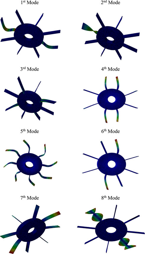
FIGURE 6. First eight modes of vibration from FE modal analysis.
The six bending modes of a steam turbine bladed disk indicate flexural deformations influencing stress and fatigue. These modes, defined by frequencies outlined in Table 2, are crucial for assessing blade integrity. Two additional modes involving both bending and twisting add complexity to the system’s dynamics, influencing stability and reliability within turbine operations.
5.7 Temperature dependence
During operation, the blades endure stresses arising from various factors including the elevated temperature of steam or gases, centrifugal force, creep, thermal gradients resulting from start-up and shutdown processes, vibration fatigue, and stresses induced by the complexity in geometry and hot corrosion reported by Amroune et al. (2018). In this paper, the temperature-dependent properties of 304 stainless steel during the steam turbine blade operation were used in the developed models. Following the preceding inputs, the temperature dependence was established by selecting the material from MPDB software Vision 9.36. Subsequently, the property section was accessed to display the data. The data on temperature-dependence were gathered, as illustrated in Figures 7–10.
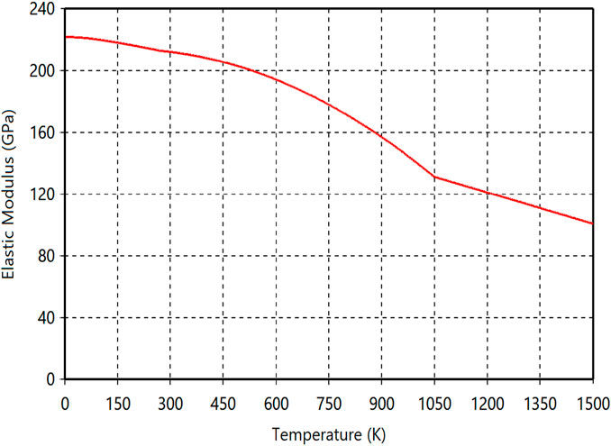
FIGURE 7. Temperature vs. elastic modulus.
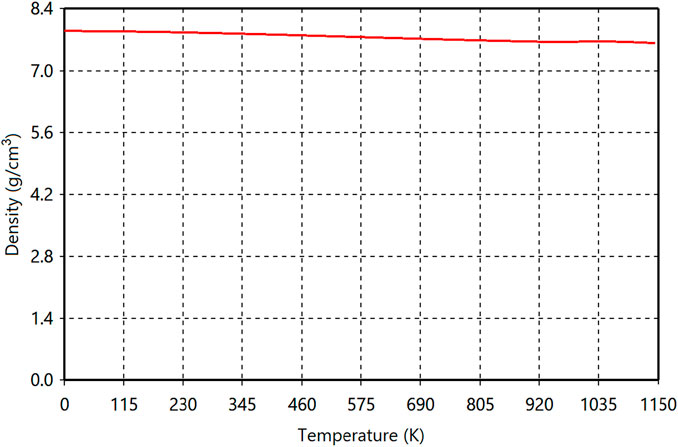
FIGURE 8. Temperature vs. density.
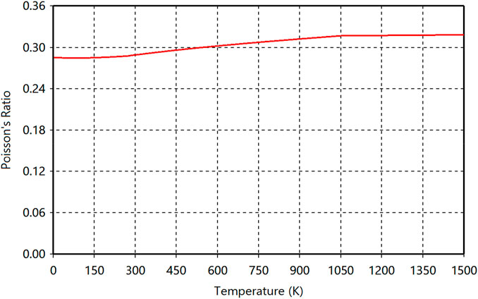
FIGURE 9. Temperature vs. Poisson’s ratio.
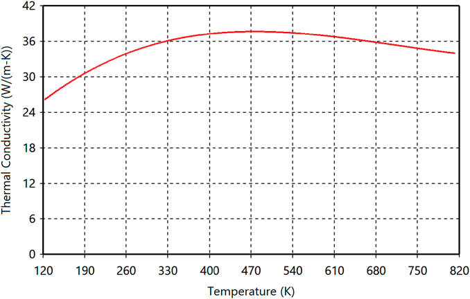
FIGURE 10. Temperature vs. thermal conductivity.
The material properties of 304 stainless steel in our ABAQUS model were updated with data on temperature-independence. This involved selecting “use temperature-dependent data” under the general and mechanical settings and inputting the data as depicted in Figures 7–10. These adjustments account for the real operating temperatures of turbine blades, underscoring the high-temperature conditions in which they function.
5.8 Dynamic stress and deformation field output
Based on a mode-based dynamic stress analysis, as expected, the maximum stress distribution on the steam turbine blade (hot spot) was at the roots of the blades, as shown in Figure 11, where (a) is a full view of the eight-bladed disk and (b) is the blade root area. Ogunbiyi et al. (2019) reported that the blade root area is where the steam turbine blade experiences the largest stress gradient. These areas are considered to be the stress concentration areas, with high possible fatigue failure. These results are consistent with those of the recent studies on HCF damage illustrated in Mashiachidi and Desai (2023).
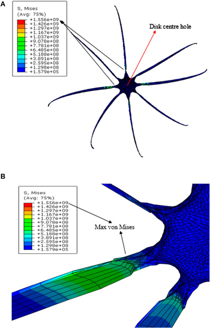
FIGURE 11. Dynamic von Mises Maxima on Bladed Disk. (A): Full View, (B): Blade Root Area.
The results of the said analysis will be subsequently used in HCF life calculations. The maximum modal-based von Mises stress found to occur at the two opposing blade roots is 155.6 MPa, as shown in Figure 11. The von Mises stress is equivalent to the mean stress (Mashiachidi and Desai, 2023).
Mashiachidi and Desai (2023) established the distinction between HCF and LCF by comparing both simulated stress and analytical centrifugal force with the yield strength. In this study, both the analytical centrifugal force and mean stresses surpass 205 MPa yield strength, as illustrated in Table 1. Given the absence of yielding, this paper is focused on HCF.
Figure 12 illustrates the deformation profile along the turbine blade. The maximum deformation occurs at the tip of the trailing edge, indicating a potential area of failure during operation. In high-temperature environments, thermal influences profoundly impact structural responses. This underscores the rationale behind the smaller sizes at the tip of the blades. Figures 11, 12 depict the mechanical behavior of the bladed disk under elevated temperatures.
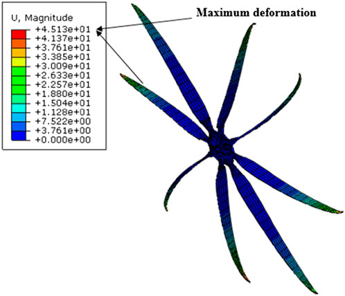
FIGURE 12. Total deformation across the turbine bladed disk.
6 HCF life prediction
The Brown–Miller multiaxial method was selected as the prescribed HCF life calculation algorithm due to its accuracy. According to Mofoka (2018), the fatigue life of each node is calculated in Fe-Safe using the summarized procedure. Hence, the fatigue life prediction is regarded as the minimum/shortest life resulting at any node in the Fe-Safe software internal fatigue calculation (Mofoka, 2018).
In this procedure, the obtained maximum dynamic stress distribution results from the steady-state dynamic stress analysis are subsequently exported as an .obd file from ABAQUS software to Fe-Safe software. Fe-Safe was employed to execute fatigue life models for all 17 scenarios involving various geometric mistuned patterns. The calculated fatigue life for the tuned (reference) cyclic bladed disk model indicated a minimum of 4.58730 on the loglife scale, corresponding to 4.58730 ×
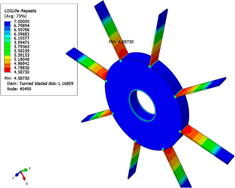
FIGURE 13. Fe-Safe fatigue life of the tuned model.
It can be concluded that fatigue failure occurs at the stress-concentrated point on the blade root location depicted in Figure 13 and previously projected by the FEA results in Figure 11. In this investigation, the previously mentioned approach of conducting a single simulation is used in both the FE simulation, as illustrated in Figures 11, 12, and in Fe-Safe life cycles, as depicted in Table 3. This implementation is aimed at minimizing computational expenses. Furthermore, as illustrated, the detailed fatigue life cycles due to length, width, and thickness changed in 17 cases in the decreasing order.
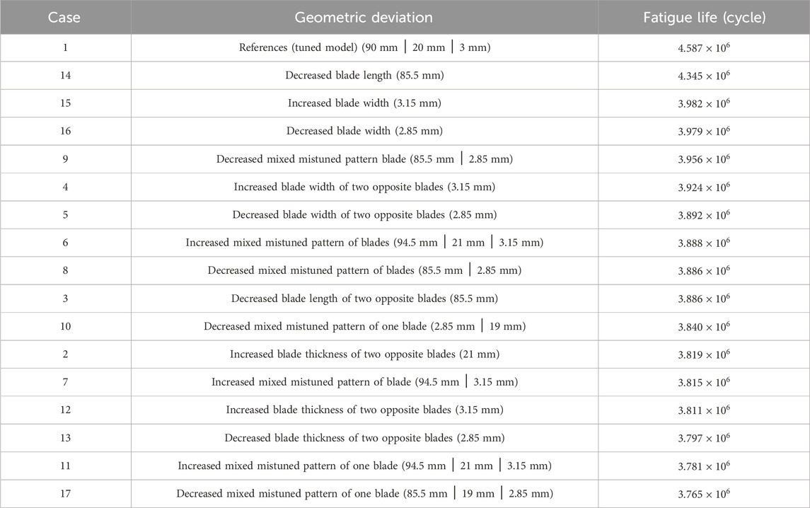
TABLE 3. Sensitivity analysis of 304 stainless steel within
Orsagh and Roemer (2002) indicated that a 5% manufacturing scatter is regarded as an acceptable tolerance within the manufacturing industry for LP steam turbine blades. Consequently, a probabilistic method was used to introduce a
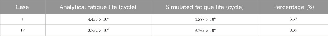
TABLE 4. Analytical and simulated fatigue life comparison.
Table 4 illustrates the comparison and validation between the analytical and simulated life cycle results of randomly chosen cases. Case 1 is the tuned blade, while case 17 is the mistuned blade. The percentage errors of the two cases are close to each other.
Engineering approximations of numerical data have been made when necessary due to insufficient information on mistuned blades, turbine performance, and material fatigue data. Analytical life cycles and Fe-Safe software show a percentage difference of 0.35%–3.37%. The procedure was to individually manipulate the blade geometries based on these geometric configurations and their respective fatigue cycles to failure.
The maximum simulated fatigue life cycle is
7 Conclusion
This paper presents predictions for the minimum and maximum lifespan of the LP stage of a 1:5-scaled geometric steam turbine bladed disk under HCF conditions with temperature-dependent variables. Using finite element analysis (FEA), we calculated the potential damages to a blade-disk subjected to centrifugal loads, pressure, and rotational velocity.
Through FE-based numerical analysis, von Mises stresses were derived, and the Brown–Miller approaches were used to compute the minimum life and maximum damage of the blade. The incorporation of more analysis variables in the Brown–Miller method enhances the accuracy of life predictions for steam turbine blades.
However, the results in this paper indicate that fatigue failure initiates at the blade root areas, which corresponds to established research. The primary vibration characteristics, such as natural frequencies, correspond with literature values as presented in Table 4.
The mechanical response of a bladed disk is influenced by temperature variations in a temperature-dependent manner. This impact is evident in the twisting and bending of blades, accompanied by deformations observed at the blade tip. Additionally, high stress concentrations are notably observed at the blade roots.
Comparing analytical and simulated results shows a maximum difference of 3.37%, attributed to slight variations in stress locations, engineering approximations in numerical data, formulaic representations, and inherent characteristics of FEA, mesh sizing, and material fatigue data. Table 3 shows that fatigue life is most sensitive to changes in blade length, followed by width, and then thickness, in this sequence.
Furthermore, the developed numerical methodology can be applied to practical steam turbine situations, offering insights into potential damage and lifespan considerations.
Data availability statement
The original contributions presented in the study are included in the article/Supplementary Material; further inquiries can be directed to the corresponding author.
Author contributions
MM: formal analysis, investigation, methodology, validation, visualization, and writing–original draft. DD: conceptualization, formal analysis, methodology, supervision, visualization, writing–review and editing, and investigation.
Funding
The author(s) declare that no financial support was received for the research, authorship, and/or publication of this article.
Acknowledgments
The authors would like to hereby express their sincere acknowledgment to Tshwane University of Technology for its unwavering support.
Conflict of interest
The authors declare that the research was conducted in the absence of any commercial or financial relationships that could be construed as a potential conflict of interest.
Publisher’s note
All claims expressed in this article are solely those of the authors and do not necessarily represent those of their affiliated organizations, or those of the publisher, the editors, and the reviewers. Any product that may be evaluated in this article, or claim that may be made by its manufacturer, is not guaranteed or endorsed by the publisher.
References
Amroune, S., Mohamad, B., Moussaoui, M., and Saaidi, H. (2018). Geometric regeneration and mechanical analysis of a gas turbine blade type Frame 9001 GE. Eng. Solid Mech. 6, 105–112. doi:10.5267/J.ESM.2018.3.003
Bathias, C., and Pineau, A. (2013). Fatigue of materials and structures: fundamentals. United States: Wiley Online Library. doi:10.1002/9781118623435
Booysen, C., Heyns, P. S., Hindley, M. P., and Scheepers, R. (2015). Fatigue life assessment of a low-pressure steam turbine blade during transient resonant conditions using a probabilistic approach. Int. J. Fatigue 73, 17–26. doi:10.1016/j.ijfatigue.2014.11.007
Das, G., Ghosh Chowdhury, S., Kumar Ray, A., Kumar Das, S., and Kumar Bhattacharya, D. (2003). Turbine blade failure in a thermal power plant. Eng. Fail. Anal. 10 (1), 85–91. doi:10.1016/S1350-6307(02)00022-5
Da-Yi, Z., Jie, H., Yan-Hong, M., and Lulu, C. (2012). A probability method for prediction on High Cycle Fatigue of blades caused by aerodynamic loads. Adv. Eng. Softw. 42 (12), 1059–1073. doi:10.1016/j.advengsoft.2011.07.010
Desai, D. (2010). Prediction and reduction of low-frequency vibro-acoustic transmission through automotive door mounts (D.Tech. Mechanical Engineering). Tshwane: Tshwane University of Technology.
eFatigue (2017). Multiaxial strain-life technical BackgroundFatigue calculator. Available at: https://www.efatigue.com/multiaxial/background/strainlife.html.
Han, Z., Wang, K., Lu, L., Wu, Y., and Wang, C. (2019). Fatigue damage assessment method of turbine shafts' torsional vibrations under SSO incidents. Eng. Fail. Anal. 105, 627–637. doi:10.1016/j.engfailanal.2019.07.030
Heidar, M., and Amini, K. (2017). Structural modification of a steam turbine blade. IOP Conf. Ser. Mater. Sci. Eng. 203, 1–6. doi:10.1088/1757-899X/203/1/012007
Henry, D. A., DiCristoforo, P. E., Ewer, T. J., and Mindock, M. (1998). Redesign of the last two stages of a mechanical drive steam turbine. Proc. Turbomach. Symposium 1998, 119–127. doi:10.21423/R1V66C
Kubiak Sz, J., Segura, J. A., Gonzalez, R. G., García, J. C., Sierra E, F., Nebradt G, J., et al. (2009). Failure analysis of the 350 MW steam turbine blade root. Eng. Fail. Anal. 16 (4), 1270–1281. doi:10.1016/J.ENGFAILANAL.2008.08.015
Kubiak Sz, J., Urquiza, G. B., Garcı´a, J. C., and Sierra, F. E. (2007). Failure analysis of steam turbine last stage blade tenon and shroud. Eng. Fail. Anal. 14 (8), 1476–1487. doi:10.1016/j.engfailanal.2007.01.012
Laibi, Y. Q., and Shather, S. K. (2020). Effect of SiC-Cu electrode on material removal rate, tool wear and surface roughness in EDM process. Eng. Technol. J. 38 (9A), 1406–1413. doi:10.30684/etj.v38i9A.552
Liu, Y., and Mahadevan, S. (2005). Multiaxial high-cycle fatigue criterion and life prediction for metals. Int. J. Fatigue 27 (7), 790–800. doi:10.1016/j.ijfatigue.2005.01.003
Liu, Y., and Mahadevan, S. (2007). Stochastic fatigue damage modeling under variable amplitude loading. Int. J. Fatigue 29 (6), 1149–1161. doi:10.1016/j.ijfatigue.2006.09.009
Liu, Z., Fard, M., and Davy, J. L. (2016). “Acoustic properties of the porous material in a car cabin model,” in The 23rd International Congress on Sound and Vibration, Athens, Greece, 10/07/2016 - 14/07/2016.
Mashiachidi, M. H., and Desai, D. A. (2023). “Prediction of fatigue life of mistuned steam turbine blades subjected to variations in blade geometry,” in Proceedings of the 11th International Conference on Advanced Technologies (ICAT '23), Istanbul, Turkey, 17-19.08.2023, 89–94. doi:10.58190/icat.2023.22
McCloskey, T. H., Dooley, R. B., and McNaughton, W. P. (1999). Turbine steam path damage: theory and practice. Palo Alto, California, USA: Electric Power Research Institute-Turbine Fundamentals.
Meyer, C. F. (2003). Applications of fluids mechanics part 3. Pretoria: CM TEK Lecture materials cc.
Mofoka, T. K. (2018). Fatigue life prediction of mistuned turbomachinery blades (M.Tech. Mechanical Engineering). Pretoria, South Africa: Tshwane University of Technology.
Mukhopadhay, N. K., Ghosh Chowdhury, S., Das, G., Chattoraj, I., Das, S. K., and Bhattacharya, D. K. (1998). An investigation of the failure of low-pressure steam turbine blades. Eng. Fail. Anal. 5 (3), 181–193. doi:10.1016/s1350-6307(98)00016-8
Ocaña, J. L., Morales, M., Porro, J. A., Correa, C., García-Ballesteros, J. J., and García, O. (2015). Numerical modelling and experimental implementation of laser shock micro-forming of thin metal sheets. Int. J. Microstruct. Mater. Prop. 10 (1), 31–46. doi:10.1504/IJMMP.2015.068314
Ogunbiyi, O. F., Salifu, S. A., Jamiru, T., Sadiku, E. R., and Adesina, O. T. (2019). Thermo-mechanical simulation of steam turbine blade with spark plasma sintering fabricated Inconel 738LC superalloy properties. Conf. South Afr. Adv. Mater. Initiative 655, 012046. doi:10.1088/1757-899X/655/1/012046
Orsagh, R. F., and Roemer, M. J. (2002). Examination of successful modal analysis techniques used for bladed-disk assemblies (Report). New York: Impact Technologies.
Peridas, G., Korsunsky, A., and Hills, D. (2003). The relationship between the Dang Van criterion and the traditional bulk fatigue criteria. J. Strain Analysis Eng. Des. 38 (3), 201–206. doi:10.1243/030932403765310536
Qin, C. (2015). Fatigue life prediction of a turbomachine blade – a probabilistic approach (M.Tech. Mechanical Engineering). Tshwane: Tshwane University of Technology.
Rani, P., and Agrawal, A. K. (2023). Fatigue life evaluation of a low pressure stage steam turbine blade. J. Vib. Eng. Technol. 2023, 1–13. doi:10.1007/s42417-023-01173-3
Rao, J., and Vyas, N. (1996). Determination of blade stresses under constant speed and transient conditions with nonlinear damping. J. Eng. gas turbines power 118 (2), 424–433. doi:10.1115/1.2816607
Rao, J. S., and Saldanha, A. (2003). Turbomachine blade damping. J. Sound Vib. 262 (3), 731–738. doi:10.1016/S0022-460X(03)00120-2
Rieger, N. (1988). “The diagnosis and correction of steam turbine blade problems,” in Rotordynamics 2 (Vienna: Springer), 453–483.
Santecchia, E., Musharavati, A., Zalneszhad, E., Cabibbo, M., El Mehitedi, M., Spigarelli, S., et al. (2016). A review on fatigue life prediction methods for metals. Adv. Mater. Sci. Eng. 2016, 1–26. doi:10.1155/2016/9573524
Schönleitner, F., Traussnig, L., Marn, A., and Heitmeir, F. (2015). Detection of blade mistuning in a low-pressure turbine rotor resulting from manufacturing tolerances and differences in blade mounting. J. Mech. Eng. Automation 5 (5), 297–308. doi:10.17265/2159-5275/2015.05.005
Simmons, H. R., and Allison, T. C. (2010). Impulse testing and blade load simulation tools to estimate cyclic stress life in blades and impellers. ASME turbo expo 2010: power for land, sea, and air. Am. Soc. Mech. Eng. 2010, 777–787. doi:10.1115/GT2010-23745
Vyas, N. S., Sidharth, , and Rao, J. S. (1997). Dynamic stress analysis and a fracture mechanics approach to life prediction of turbine blades. Mech. Mach. Theory 32 (4), 511–527. doi:10.1016/S0094-114X(96)00067-5
Winkler, A., Holt, S., and Vallance, L. (2012). “Concerning the synergy of stress and strain-based methods in modern metal fatigue analysis,” in AVL Advanced Simulation Technologies User Conference. Available at: https://www.researchgate.net/publication/278004312.
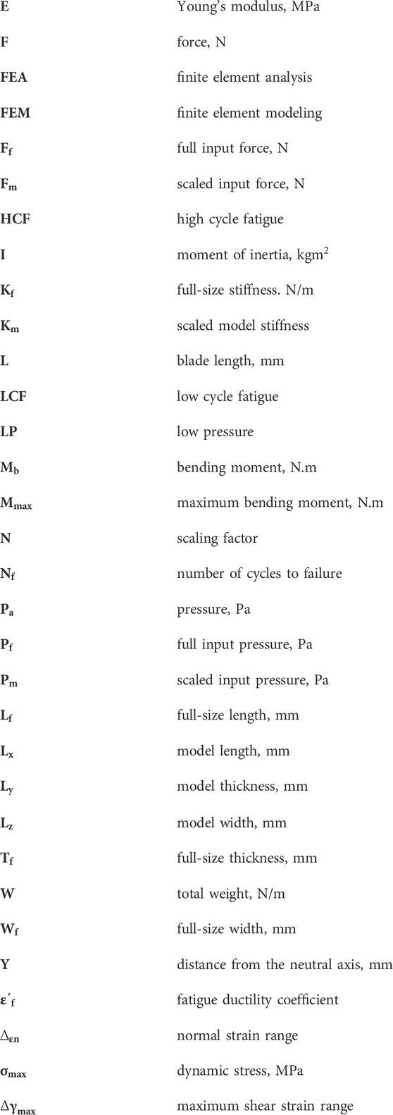
Nomenclature
Keywords: geometrically mistuned turbine blades, manufactured blade geometry, finite element analysis, low-pressure turbine, fatigue life, Fe-Safe
Citation: Mashiachidi MH and Desai DA (2024) Prediction of fatigue life of geometrically deviated steam turbine blades under thermo-mechanical conditions. Front. Manuf. Technol. 3:1338222. doi: 10.3389/fmtec.2023.1338222
Received: 14 November 2023; Accepted: 20 December 2023;
Published: 11 January 2024.
Edited by:
Angelos P. Markopoulos, National Technical University of Athens, GreeceReviewed by:
Nikolaos Karkalos, National Technical University of Athens, GreeceVictor Rizov, University of Architecture, Civil Engineering and Geodesy, Bulgaria
Lawrance G., Karunya Institute of Technology and Sciences, India
Xingyuan Zheng, Southeast University, China
Copyright © 2024 Mashiachidi and Desai. This is an open-access article distributed under the terms of the Creative Commons Attribution License (CC BY). The use, distribution or reproduction in other forums is permitted, provided the original author(s) and the copyright owner(s) are credited and that the original publication in this journal is cited, in accordance with accepted academic practice. No use, distribution or reproduction is permitted which does not comply with these terms.
*Correspondence: Makgwantsha Hermelton Mashiachidi, 212200816@tut4life.ac.za