In Vivo Neural Interfaces—From Small- to Large-Scale Recording
 Bingjie Zhang
 Chunshan Deng1
  Chunzhi Cai
 Xiaojian Li
- 1CAS Key Laboratory of Brain Connectome and Manipulation, The Brain Cognition and Brain Disease Institute, Shenzhen Institute of Advanced Technology, Chinese Academy of Sciences, Shenzhen-Hong Kong Institute of Brain Science-Shenzhen Fundamental Research Institutions, Shenzhen, China
- 2Nano Science and Technology Institute, University of Science and Technology of China, Suzhou, China
- 3Division of Biological and Environmental Sciences and Engineering (BESE), King Abdullah University of Science and Technology, Thuwal, Saudi Arabia
Brain functions arise from the coordinated activation of neuronal assemblies distributed across multiple brain regions. The electrical potential from the neuron captured by the electrode can be processed to extract brain information. A large number of densely and simultaneously recorded neuronal potential signals from neurons spanning multiple brain regions contribute to the insight of specific behaviors encoded by the neural ensembles. In this review, we focused on the neural interfaces developed for small- to large-scale recordings and discussed the developmental challenges and strategies in microsystem, electrode device, and interface material levels for the future larger-scale neural ensemble recordings.
Introduction
The functions of our brain, including sensation and cognition, motor control, learning, and memory, are achieved by the coordinated activity of neural populations distributed across multiple brain regions. The brain itself is very soft and immersed in the cerebrospinal fluid composed of electrolytes. The brain is also surrounded, protected, and supported by the pia, arachnoid, dura, and skull.
Neurons are the main basic units that enable brain function. It is an electrically excitable cell that receives, processes, and transmits information (Rastogi and Cohen-Karni, 2019). The typical morphology of a neuron includes a cell body called soma, slim dendritic branches called dendrites, and fiber axons extending away from the soma. The dendrites receive signals from other neurons, while axons transmit signals to others. The electrical signals transmitted by the axons are called action potentials (APs). Synapses are the junctions for communication between neurons (Alexander, 1986). Communication between neurons is accomplished by gated ion flow via chemicals across chemical synapses or potentials across electrical synapses. The superimposed effect of the electrical activity of neurons in the extracellular medium creates potentials and gradient electric fields across the brain tissue. These electric field signals can be monitored by placing electrodes outside the neuron.
Their waveform characteristics, including amplitude and frequency, are determined by the vector sum of multiple potential sources, the properties of the brain region, and the impedance and effective contact area of the recording electrodes. Depending on the placement of the recording electrodes, the recorded electrical signals can be classified into four types (Figure 1) (Rastogi and Cohen-Karni, 2019):
1) Electroencephalography (EEG) signals are recorded from the scalp and are slow-wave signals (5–300 μV, <100 Hz).
2) Electrocorticogram (ECoG) signals are recorded from the surface of the cerebral cortex and are medium rhythms (1 μV–500 μV, <200 Hz).
3) Local field potential (LFP) is mainly recorded in the brain tissue. It is the superimposed effect of the potential formed by all ionic processes around the electrode and is a faster rhythmic signal (<1 mV, <300 Hz).
(4) Action potential (AP), which is electrical pulses emitted by a single neuron, can have an amplitude of more than 500 μV and a frequency band of 300–7 kHz when measured extracellularly.
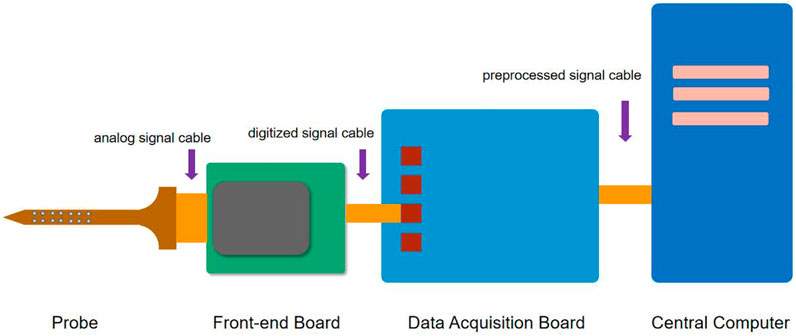
FIGURE 1. Implanted locations of surface-attached type arrays, microwire and Michigan arrays, Utah array, and flexible polymer probe array in the brain, and fixed locations of the plugs in the skull.
The action potential is the signal with the highest information accuracy and fidelity among the extracellularly recorded signals. It is extracted from single-unit activity (SUA) and multi-unit activity (MUA) recorded from a cluster of functionally connected single neurons. LFPs are generated when synaptic currents in a single neuron are synchronized and current coupling is formed with neighboring neurons. APs are in the higher frequency band and are not significantly represented in the LFP band. Compared to single and multi-unit activity signals, LFPs are more robust across changes in electrode sensitivity or position. The temporal resolution of the neural signals recorded in brain tissue was able to reach approximately 3 ms, while the spatial resolution varied from each other. The highest spatial resolution for single-unit activity recordings was around 0.05 mm, followed by 0.10 mm for multi-unit activity recordings and 0.50 mm for LFPs (Martini et al., 2020).
ECoG signals were derived from the synchronized postsynaptic potential activity of a large number of cortical pyramidal neurons. Similar to the LFP signal, the ECoG is less susceptible to the relative micromotion of electrodes in brain tissue than the single neuron recordings (Martini et al., 2020). However, ECoG is recorded on the surface of the cerebral cortex, and the signal is somewhat attenuated as it passes through the cortical neural layer, the pia, the arachnoid, and the cerebrospinal fluid, so the spatial and temporal resolutions of the ECoG signal are both slightly lower than that of the signal recorded in the cortex (Yuen et al., 1987). The temporal resolution of the ECoG signal is about 5 ms and the spatial resolution is about 1 mm (Asano et al., 2005). The ECoG electrode does not pierce into the cortical neural tissue and does not cause significant gliosis and scarring, nor does it cause intraparenchymal hemorrhage. Electroencephalography (EEG) is the recording of signals from the scalp. The temporal and spatial resolution of EEG is much lower than that of ECoG because the neural signal is significantly attenuated by the thick skull with low electrical conductivity. It has a temporal resolution of about 50 ms and a spatial resolution of about 10 mm (Vallabhaneni et al., 2005). Thus, it can be roughly estimated that if the spatiotemporal resolution value of EEG is 1, then ECoG is 100, LFP about 300, MUA about 1,500, and SUA about 3,000.
Non-invasive techniques such as EEG are carried out in non-invasive brain-machine interfaces. The performance is still difficult to meet practical requirements due to high signal distortion, poor specificity, and low resolution in the direction of neural prostheses (Martini et al., 2020). The implantable technique has much higher signal quality but requires surgical implantation of electrodes inside the skull. One of these techniques, ECoG, requires electrodes to be placed inside or outside the dura mater, called subdural ECoG and epidural ECoG, respectively. Compared to EEG, data acquired by subdural ECoG electrode arrays have a much higher spatial and temporal resolution but do not reach the neuronal APs (Jayakar et al., 2016). The penetrating electrodes can increase the resolution of the spiking event but the space range of penetration is limited by the fact that brain tissue will be damaged. Especially when used for long-term chronic recordings, the penetrating electrodes may trigger permanent local brain tissue damage. However, extracellular recording electrodes penetrating the brain tissue can acquire action potential (AP) and LFP signals at any depth in the brain. It acquires extracellular neural electrical signals with the highest temporal and spatial resolution and therefore has the most extensive application in neurophysiological studies. In this review, the so-called “neural interface” we discussed is focused on the way in which sensors touch the neural tissue to collect the neural signals, so EEG and epidural ECoG are not within the discussion.
The extracellular neurophysiological recording is the process of transmitting the neural signals captured by microelectrodes implanted in the brain, with minimal distortion and delay, to a remote computing unit that processes, store, and visualizes the data in real-time. The components of a conventional recording system include (Figure 2) (Putzeys et al., 2020) the following:
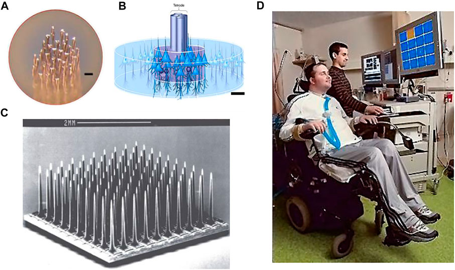
FIGURE 2. Pipeline and components of a conventional recording system.
1) A set of passive electrode probes with electrical signal sensing contacts are connected through flexible or rigid connecting wires to 2) a headstage for pre-amplification of the neural signals. In the up-to-date designs, the signals are amplified and digitized here and transmitted via a long signal cable to the 3) data acquisition unit, which performs signal preprocessing and transmits the data to the 4) central computer with powerful computation capabilities for data processing, storage, and visualization.
In this review, we would rather focus on the neural interface which is the front-end of the system than discusses much of the signal processing and data computation of the recording system (this is a lot and can be discussed in another article), consisting of the electrode probe and the headstage.
The development of in vivo neuroelectrophysiological techniques from single electrode recording at the early stage has so far achieved over 1,000 channels simultaneous of recording capability in a single recording device or module. The expansion of the neural signal recording scale is not only the increase of channel count but also the expansion of the recording spatial range with ensured sampling spatial density (matching the spatial resolution of the corresponding signal). To simplify the classification, we roughly divided the record scale into three levels: small, medium, and large. The channel count is less than 100, a record cover of less than 1 mm is small scale; channel count more than 100 and a coverage of less than 1 cm is medium scale; thousands of channel count and cover over 1 cm is large scale. This is not an absolute criterion, we just show technical trends.
Small-to-Medium-Scale Recording
We find that the scale-up of the electrode types described below from small scale to medium scale are not big technical challenges, which are small process changes, so they are discussed together.
Penetrating Type
Microwire Electrodes
The microwire electrode is a long-established microelectrode used for electrophysiological studies, and its use dates back to the 1940s (Sscwartz, 2004). The core of a microwire electrode is a conductive metal wire, which is surrounded by an insulating material (such as polymer, ceramic, or glass) that is resistant to electrolyte solutions. (Figure 3A). Only the tiny metal tip is exposed. The glass-coated tungsten microwire electrodes can be fabricated with simple tools and their tips can reach the same size as the soma of the cortical neuron. Using this electrode, the extracellular neural activity signals close to the firing neurons have been recorded for the first time with high signal-to-noise ratios. The neural recording technology based on this electrode has made a lot of important contributions in the history of neuroscience research, with pioneering studies in brain regions such as the primary visual cortex, hippocampus, inferior temporal cortex, and the neural correlations of perceptual sensation and movement control (Hubel and Wiesel, 1959; O'Keefe and Dostrovsky, 1971; Desimone et al., 1984; Newsome and Pare, 1988). The chronic recording experiments have shown that microwire electrodes less than 20 µm in diameter significantly reduce the foreign body response to the inserted microwires.
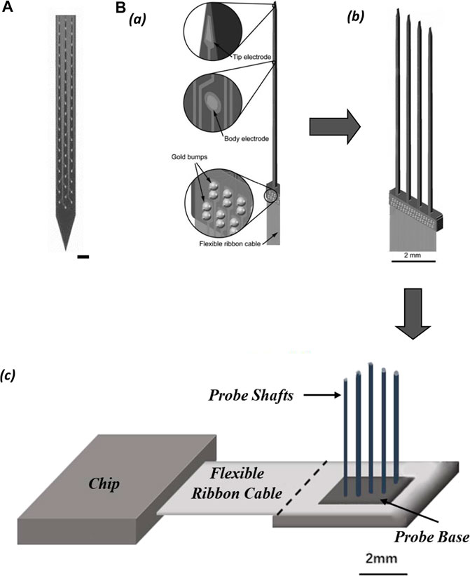
FIGURE 3. (A) Features of the microwire electrodes array (scale bar 10 µm). (B) Illustration of tetrode in the neural tissue; (scale bar 25 µm). (C) Utah array. (D) Clinical investigation of the intracortical brain–machine interface.
The tetrode is a small four-channel bundle array of electrodes consisting of four microwires. The tetrode allows the simultaneous detection of neuronal signals from the same source by four electrode sites from slightly different locations (Figure 3B). The diameter of the metal contact of each electrode in this small array is typically less than 30 μm (Mcnaughton et al., 1983). The main advantage of tetrodes over single-channel electrodes is that the extracellular potentials detected by the four electrodes differ due to the different distances between each electrode and the neuron (Hubel, 1957). The classification of extracellular potential signals using a clustering approach enables the separation of the spiking events emitted by the adjacent neurons (Choi et al., 2018).
The single and multiwire electrodes are basically handmade, which are expensive to manufacture manually and cannot be mass produced (still can exceed 100 channels, over 1 mm coverage). These microelectrodes are often considered an “art” due to the low precision of processing and the low reproducibility of metrics, such as impedance and shape. However, because they can be fabricated by hand, this technique is widely used in many neurophysiology laboratories.
Utah Array
The Utah array is a commercially available electrode array for intracortical implantation, which adopts an out-of-plane process. The Utah array (medium scale) consisted of approximately 100 silicon needle shaped electrodes spaced 400 μm with exposed tips of diameter 10–30 μm (Figure 3C). The array is fabricated through MEMS technology with chemical micromachining, metal deposition, and polymer encapsulation (Campbell et al., 1990). Neuroscientists needed long-term stable chronic neural recording in the brain and have come up with the idea of enclosing the entire electrode array inside the skull. The Utah array is designed to solve the problem of closing the skull after implantation of a planar electrode array with the support substrate and connecting leads. Because the Utah array has the advantages of high channel count, balanced cortical coverage to electrode density, and chronic recording feature, it is mainly used in large animals, especially non-human primates. However, the tip of the silicon electrode is short (typically no more than 1.5 mm), and it is only suitable for recording neural signals from the cortex. Utah electrodes are similar to microwire electrodes in that electrode contact is only on the tip of each shaft. Inserting all nearly 100 probes of a dense array into the cortex at the same time is difficult, requires the use of a special micro air hammer to implant them (Normann, 2007; Wark et al., 2013; Choi et al., 2018) (Figure 5D).
The Utah array and its recording system have been approved by the U.S. Food and Drug Administration (FDA) for clinical investigations of intracortical brain-machine interface technology (iBMI). The Utah arrays are currently used primarily in clinical trials of motor brain-machine interfaces, which replace and restore the injured motor function in paralyzed patients by transmitting motor-related neural signals from the brain to external effectors (Figure 3D). The main approach is to implant one or more (two) Utah arrays in the region of the cerebral cortex responsible for limb movements in the patient’s brain. In non-human primate experiments, the simultaneous implantation of multiple Utah arrays with a total of more than 500 channels in the visual cortex of the same macaque monkey has been achieved so far (Collinger et al., 2013).
Michigan-Type Probes
Another commercially available microelectrode array, the Michigan probe, is manufactured using an in-plane machining process. The “Michigan” probe was the first silicon-based neural electrode array fabricated in 1970. It is manufactured using micro-electro-mechanical system (MEMS) that includes techniques such as depositing metals on silicon and etching (Wise et al., 1970). A Michigan electrode is a flat rod with multiple recording contacts lined up along the wide side of the flat rod (small scale generally), and the contact surface area is typically between 100–400 μm2. The advantage of this manufacturing process is that the spacing between electrode contacts can be precisely controlled and the diameter of the contacts can be as small as 2 μm, while the length of the entire probe can vary from a few millimeters to centimeters, making the Michigan electrode more suitable for recording brain tissue structures from the longitudinal direction.
Polytrodes probe is a variant of the Michigan probe designed for intensively extracellular multi-unit recording in a cluster of adjacent neurons (Figure 4A). The shank of the polytrode probe is arranged with multiple closely spaced recording sites, equivalent to an enhanced version of the tetrode in single-unit isolation function, and can record up to three times as many neurons as the number of electrode contacts. The high-precision lithographic process ensures uniformity in the size of each recording site, and it is easier to customize the shape of the probe (single or multiple shanks) and the location of the recording sites on the shank according to the structure of the brain region to be recorded (Blanche et al., 2005).
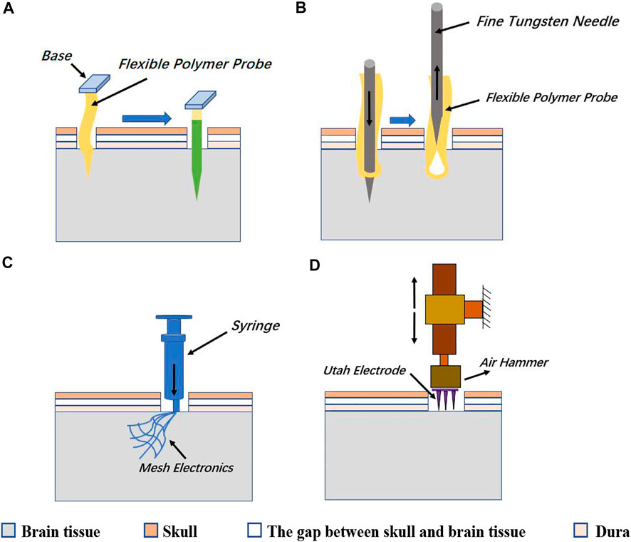
FIGURE 4. (A) Electrode contacts layout of polytrodes. (scale bar 50 µm). (B) Schematic of probe assemblies: (a) structure of single probe shaft; (b) probe comb with four shafts; (c) slim platform 3D-probe array with 4 × 4 shafts.
Multi-shank Michigan-type probes form a two-dimensional (2D) comb structure, and 2D probe combs can be further assembled into three-dimensional (3D) probe arrays. Such arrays allow dense volumetric electrophysiological recordings of neuronal networks in one brain region (Wise, 2005) (Figure 4B). One-dimensional narrow bar multi-electrode probes are expanded into high electrode density two-dimensional electrode arrays, which in turn are stacked into three-dimensional electrode matrices (often expanded to medium scale). This is a modularization solution with high scalability. The back end of the electrode matrix is connected to the integrated circuits that perform signal conditioning, multiplexing, and digitization, via high-density flexible wires. These wires effectively prevent passive electrodes from active devices in terms of mechanical, electronic, and thermal effects. In chronic recording experiments, the electrode array floating in the brain tissue and the upper side of the implanted brain tissue covered by dura and skull, are good for long-term recordings. The base of the silicon probe array for chronic recording which is not implanted into the brain tissue does impede the closing of the skull, so it has to be designed to be as short as possible. Overall, it appears that the shape of the electrode matrix for chronic recording is a hybrid style of the Michigan probe and the Utah array.
The polymer probe is a flexible polytrode probe. It is operationally flexible as a microwire electrode, while the density of recording contacts can approach that of the Michigan probe. Polymer probes are highly neuro-compatible, not only from the high biocompatibility of the polymer material but also from the ability to move with the brain tissue, thus reducing shear damage to the tissue. One improvement of the polymer probe is to cut off part of the area around the electrode contact and make the strip shape polymer probe into an open mesh structure. This design further enhanced the mechanical flexibility of the polymer probe and reduces electrical crosstalk between channel lines by disturbing the parallel interconnect wires. However, because the polymer probes tend to be soft and cannot be directly stabbed into brain tissue, auxiliary methods, such as reinforcing with water-soluble reinforcers (such as PEG) (Figure 5A), or bringing electrodes into the brain tissue with fine metal needles as the sewing machine does (Figure 5B), mesh electrode arrays can be made not only as penetrating probes but also as ECoG electrodes that adhere softly to the cortical surface without the stabbing process (Figures 5A–C).
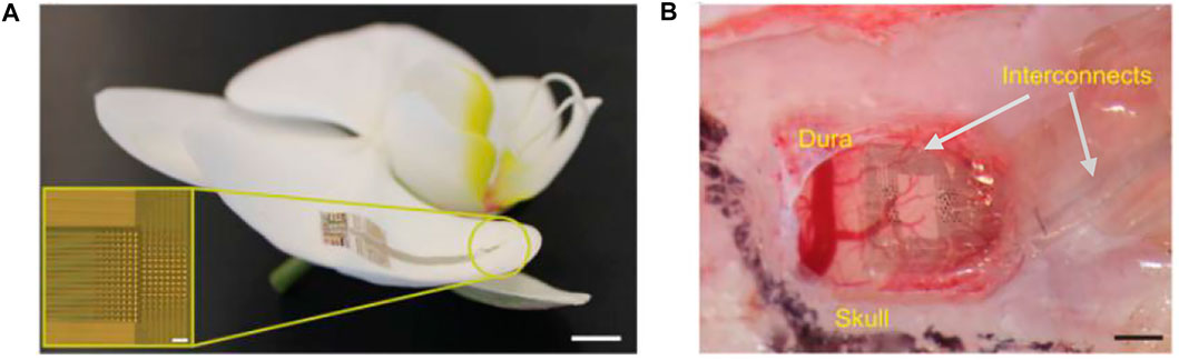
FIGURE 5. (A) One way is to wrap the flexible polymer probe with a soluble reinforcer such as PEG, and then quickly stab it into the brain tissue. After the reinforcer solves, the probe restores flexibility. (B) The other way of implanting a flexible polymer probe is to bring the probe into the brain tissue with a rigid and thin metal needle and then extracting the thin needle leaving the flexible probe in the brain tissue. (C) Mesh arrays can be injected into the brain tissue by a syringe or are directly attached to the surface of the cerebral cortex. (D) Utah array needs to be punched into the brain tissue by a small air hammer.
Surface Attached Type
Neurogrid
Neurogrid is a thin-film electrode array with 4-μm parylene C as the insulating substrate. It has electrodes with poly (3,4-ethylenedioxythiophene) doped with poly (styrenesulfonate) (PEDOT:PSS) as a gate in organic electrochemical transistors and is capable of recording the action potential of neurons from the cortical surface (Khodagholy et al., 2015). The samples of this electrode array have 256 recording sites with a surface area of 10 × 10 μm2 and an interelectrode spacing of 30 μm, matching the average size of neuronal bodies and neuronal density (Figure 6A). The interface material at the electrode contacts was made of PEDOT: PSS, whose high mixed electronic/ionic conductivity and high ionic mobility significantly decrease the electrochemical impedance mismatch between the brain tissue and the metal electrode (Owens and Malliaras, 2010; Stavrinidou et al., 2013). The encapsulation with parylene C has prepared a flexible film with a thickness of only 4 μm, allowing it to be tightly adhered to the surface of the irregularly shaped cerebral cortex. In addition, the neurogrid can be folded and inserted into the cerebral sulcus where conventional subdural ECoG electrodes for clinical use cannot be inserted (Figure 6B). Since such electrodes do not penetrate into the brain tissue, there is no need to worry about severe brain damage; they can be easily prepared for medium scale. However, it is also seen that the electrode contacts only cover a small area of the film attached to the cortical surface, and most of the area is occupied by the interconnect wires. The low coverage ratio of the practical records hindered the design of large-scale recording.
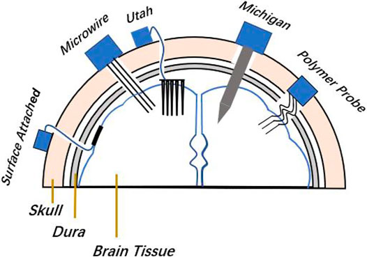
FIGURE 6. Neurogrid. (A) Neurogrid conforms to the surface of an orchid petal (scale bar, 5 mm). Inset, optical micrograph of a 256-electrode Neurogrid (scale bar, 100 μm). The electrodes are 10 × 10 μm2 with 30-μm interelectrode spacing. (B) Neurogrid conforms to the surface of the rat somatosensory cortex. (scale bar, 1 mm).
Large-Scale Recording
Under the premise of ensuring high recording electrode density, the electrical activity of a large number of neurons can be recorded across multiple brain regions simultaneously by increasing the number of recording electrodes and expanding the coverage area of brain tissue. This kind of method can provide crucial neural information for understanding the self-organized processes of neural networks and the encoding principle of specific cognitive behaviors by neuronal ensembles. Thus, large-scale recording is now an urgently needed neural technology. The following recording devices are mainly the engineering innovation of the respective basic small and medium-scale recording devices, which break through the bottleneck of the recording scale.
Penetrating Type
Neuropixels
Compared to the conventional silicon-based Michigan electrodes, the feature of this design is that complementary metal oxide semiconductor (CMOS) technology is used to realize the integration of recording electrodes and multi-channel multiplexed circuits into the same silicon probe, and the silicon probe is also integrated with the amplification, filtering, and digital signal preprocessing circuit into the same processed silicon wafer (Figure 7A).
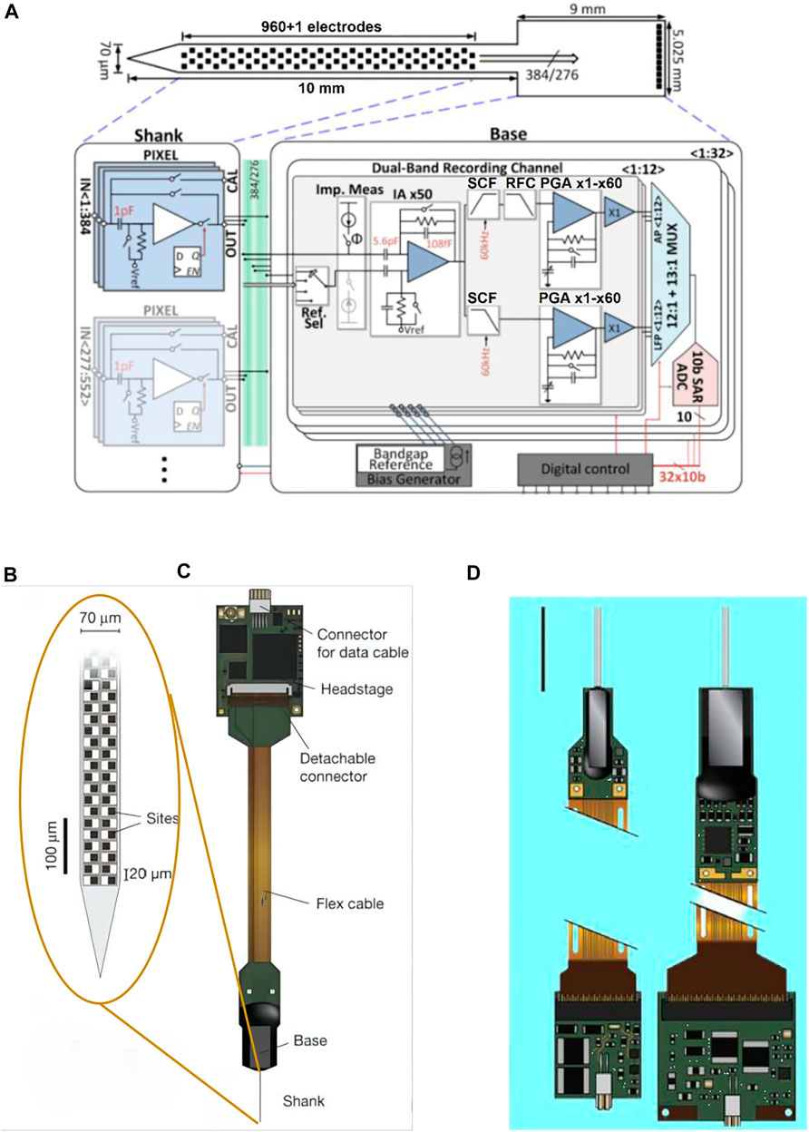
FIGURE 7. Neuropixels. (A) Illustration of the probe tip, showing checkerboard site layout (dark squares); (B) probe packaging, including flex cable and headstage for bidirectional data transmission; (C) neuropixels 2.0 probe (left) and 1.0 probe (right); and (D) system architecture of the active pixels probe.
Version 1.0 of Neuropixel is fabricated in a 130 nm CMOS process. 960 recording electrodes and the precision electronics (or: complex electronic circuits) with multiplexed addressing and local amplification functions are integrated on a 10 mm long, 70 × 20 μm cross-section rigid silicon probe. The probe shank is connected with the base via 384 connecting wires. A configurable 384-channel integrated circuit on the 5 × 9 mm2 probe base is responsible for dual-band recording (30 KHz pulse frequency and 2.5 KHz LFP frequency per channel) and to send data over 20 MB bandwidth to the acquisition board through a digital port. Although there are 960 recording sites that can be selected, only 384 signal channels can record simultaneously on neuropixel 1.0 (Jun et al., 2017) (Figures 7B,C).Version 2.0 of Neuropixel has four shanks in each probe, a total of 5,120 recording sites, which can intensively record the signals in the 1 × 10 mm plane (Figure 7D). Neuropixel 2.0 is a dual probe unit structure. So there are 10,240 recording sites and the number of simultaneously recordable channels reaches 768 but the volume of the probe shrinks to one-third of the neuropixels 1.0 (Steinmetz et al., 2021). Under the premise of ensuring thousands of recording sites, the neuropixel probe compresses the cross-sectional area and wiring amount of the probe through multiplexing and further simplifies the connection through the integration of the preprocessing chip and the probe, which greatly reduces the overall volume of the neural interface device (Putzeys et al., 2019). When recording the neural activities, this design can effectively reduce the restraint on animals.
Argo
As the longest-used microwire electrode, it can be made very slim and stiff. It not only has low insertion damage to the brain tissue but also has good recording quality. For the application of microwire electrodes in large-scale recording, it is necessary to solve the problem of connecting the electrode array composed of a large number of microwires to the amplifier array (Mal et al., 2003). The solution proposed by “Argo System” was to use a sacrificial coating to thicken the wire and then tie them into a bundle, spaced just perpendicularly coupling to the plane of the large CMOS amplifier array (Figures 8A,B).
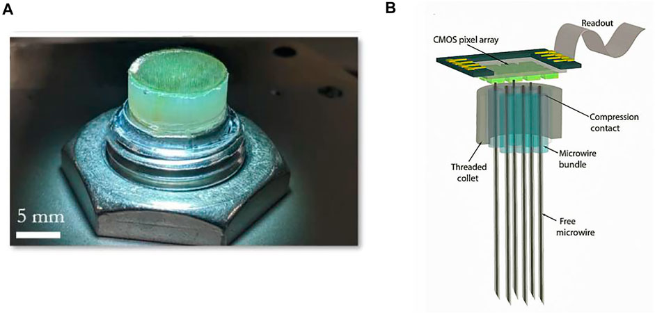
FIGURE 8. Argo. (A) Macroscopic images of the electrode array; (B) schematic of the CMOS chip integrated with the microwire bundle. The bundle consists of a proximal (chip) end.
After the butt-joint of the microwire bundle array to the amplifier array surface of the backplane, a recording device similar to the Utah array for penetrating cortex is formed. The significant progress of the Argo over the Utah array is the overall data throughput. The prototype of the Argo system has the ability to continuously record 65,536 channels at 32 kHz and 12 bits of resolution.
The prototype validates the ability to record 791 single-unit APs in the rat cortex with an array of up to 1,300 penetrating microwires. Stimulus-evoked LFPs are recorded by microwire arrays with more than 30,000 channels attached to the surface of the sheep’s auditory cortex. (Sahasrabuddhe et al., 2020). This method of grafting microwires array to the CMOS process products suitable for mass production provides a large-scale neural interface platform with further expansion.
Neuralink
Neuralink has specifically developed a robotic sewing machine that automatically implants each thread to stab into the brain tissue with the help of a fine tungsten needle hook (Musk and Neuralink, 2019; Tooker et al., 2012a; Tooker et al., 2012b) (Figures 9A,B). The sewing machine has the ability to locate specific cortical areas with machine vision and to automatically avoid the surface blood vessels for safe electrode implantation (Hanson et al., 2019) (Figure 9C). The neuralink provides a system-level solution, including an array of flexible polymer probes integrated with customized low-power electronics for signal acquisition, and implantation machinery that can automatically implant electrodes into the cortex (Figure 9D). The current wired transmission version (Figure 9D) of the system is a state-of-the-art large-scale scientific research platform for in vivo neuroelectrophysiology. The wireless version (Figure 9E) of the system is the first fully implanted front-end for preclinical investigation.
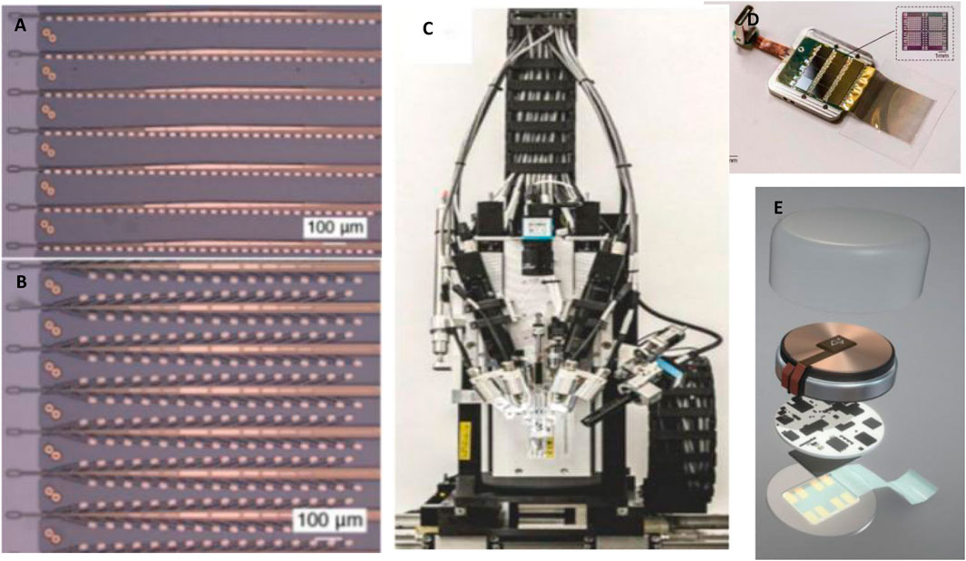
FIGURE 9. Neuralink. (A) “Linear Edge” probes, with 32 electrode contacts spaced by 50 μm; (B) “Tree” probes with 32 electrode contacts spaced by 75 μm; (C) the brain sewing machine; (D) Wired transmission; (E) The wireless implantable recording system module.
Surface Attached Type
Compared with the traditional cortical surface electrode arrays, the ultra-thin (<30 um) flexible cortical surface microelectrode (μECoG) arrays can keep good cortical recording quality over a long period, and with little irritation or damage to brain tissue after implantation (Moshayedi et al., 2014). The micro-ECoG arrays can densely sample neural electrical activity and extract richer spatiotemporal information, which can be not only used for long-term brain activity mapping but also have tremendous potential in therapeutic applications of brain-machine interfaces (Viventi et al., 2011; Won et al., 2018).
Neural Matrix
The Neural Matrix (Figure 10A) is a kind of thousand-channel-level array of μECoG electrodes. It is to greatly reduce the amount of wiring by integrating the powerline time-division multiplexing electronic device directly into the sensor to increase the ratio of electrode contact coverage to the total area of the array, and ensure high electrode density. In a neural matrix test prototype, the neural signals were recorded from a high-density electrode array with nearly 100 wires containing over 1,000 recording sites by setting up two layers of metal interconnect lines plus embedded multiplexers. The electrode array is in a 28-column by 36-row mode with a coverage of 9 × 9.24 mm2 (Figure 10B). A total of 1,008 wires are needed for the traditional electrode array but the total number of wires required for the neural matrix is only 92 (2 times columns then plus rows), saving more than 90% of the wiring area. Because cortical surface electrodes require a relatively low sampling rate (generally do not have to exceed 1 KHz), all electrode sites within the neural matrix can be sampled in a two-dimensional scanning cycle. While each channel of the neuropixels requires a much higher sampling rate, it adopts a multiplexing method that is to select recording sites with no more than the total number of recordable channels before each recording session (Chiang et al., 2020).
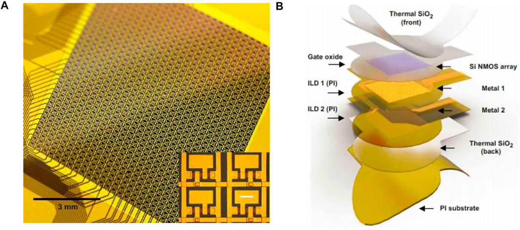
FIGURE 10. Neural matrix. (A) Photograph of 1008-ch neural matrix array. Inset: each electrode is connected to a unit cell consisting of two flexible silicon transistors. (B) Structure of a neural matrix array.
PtNRGrids
Recently, another thousand-channel-level uECoG electrode array, called PtNRGrids, is developed. It is a 6.6 um thin-film electrode array with 30 um diameter electrode contacts and low impedance by platinum nanorod modification (Figures 11A–C).The spacing of recording sites for this array can be configured between 150 μm and 1.8 mm to form a coverage area ranging from 5 × 5 mm2 (1,024 grids) for rodents to 8 × 8 cm2 (2048 grids) for the human brain. With this high spatial resolution electrode array, the investigator observed the epilepsy discharge dynamics and spatial diffusion process in patients with epilepsy surgery (Tchoe et al., 2021). Compared to the high electrode density design of the neural matrix, the PtNRGrids design passed a large number of interconnecting wires through the wide electrode spacing and achieved the large-scale recording with that the electrode contact coverage occupies most of the total area. Since the spatial resolution of the ECoG signal does not exceed the LFP signal, the sampling density of hundreds of micron spacing does not lose a lot of brain information. For the human brain, due to the larger brain surface, reducing the spatial sampling density while covering a larger brain area may be more beneficial to obtaining richer brain information. So this large-scale recording compromise with the deployment of lower electrode density is also acceptable.
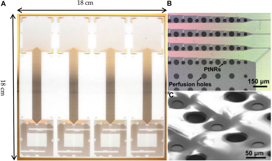
FIGURE 11. PtNRGrids. (A) Large-area fabrication of PtNRGrids electrode arrays on 18 cm–by–18 cm glass substrates.(B) Microscale features of PtNR contacts, metal leads, and perfusion holes shown by B optical (top) and (C) electron microscope images (bottom).
Distributed Type
The flexibility of this type represents the direction and future of large-scale recording (or even stimulation).
Neurograin
The large-scale recording electrode arrays mentioned above are integrated processing devices, with the location of each electrode contact determined and implanted into the brain as an ensemble. The idea of the next generation neural interface design has been proposed: the electrode implantation position can be set independently and flexibly, the scale can reach thousands, and it should have the bidirectional function of recording and stimulation (Lee et al., 2021). A proof-of-concept experiment of the distributed sensor system (Figure 12A) is completed on the cortex by microminiaturization of the device “neurograin” as a network node but maintaining high signal fidelity. The neurograin system is composed of implantable, submillimeter, individually addressable (Huang et al., 2019), and microchip sets (Figure 12B). Each neurograin is an independent packed module of 500 μm × 500µm × 35 µm and wireless powered by inductive coupling technology for near-field transmission (Lee et al., 2018). Neurograin microdevices do not need tether and can be implanted in specific brain regions individually or collectively for reading and writing neural information, with good prospects for clinical application.
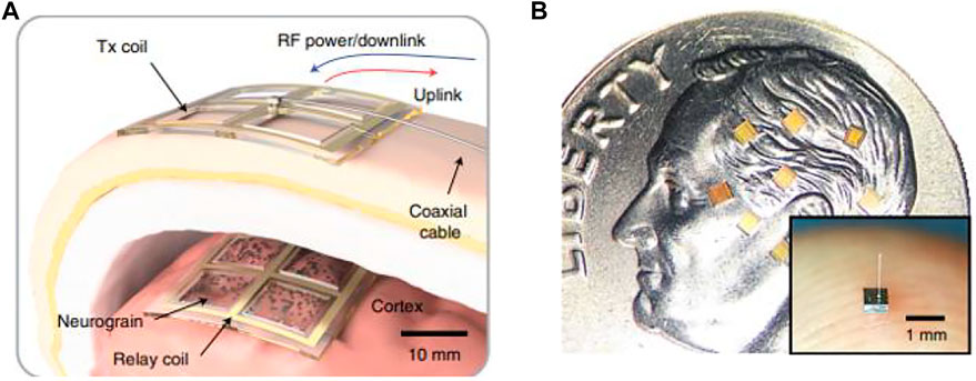
FIGURE 12. Neurograin. (A) Concept of a transcutaneous RF power and data link for a neurograin array; (B) neurograin chiplets present on a United States dime.
Discussion
From that mentioned above, the whole system design of the large-scale recording devices with the penetrating electrode was introduced, and the surface attached electrode was focused on the electrode itself. As a large-scale recording device that can be widely used, it must be presented as a system. With the requirement of portability, the front-end of the neural recording system-neural interface tends to appear in the form of a microsystem. This requires the co-design and system optimization of the high-channel count electrode array with the analog front-end circuit connected. We will make a brief discussion of some key points from the engineering design perspective in the order of system-device-material.
Microsystem
Due to the limited number of electrode contacts (usually less than 100) in traditional neural interface devices, either a large range of brain regions is sampled at a lower spatiotemporal resolution or a small volume of neurons at a higher spatiotemporal resolution. In recent years, the requirement of increasing the sampling volume and improving the sampling density was proposed under the premise of collecting the neural signals with high fidelity for scientific research and clinical application. The current large-scale neural recording technology can be suggested to have the ability to record more than 1,000 electrode contacts within the scale of 1 cm or above (Chiang et al., 2020).
The number of electrode contacts that can be recorded is mainly limited by the number of channels that can be read out in parallel and the maximum number of interconnect lines in the probe shank. Because the cross-sectional area of the probe shank determines the tissue damage of the penetrating probe, the number of interconnecting lines is limited by the width of the probe shank (Chiang et al., 2020). Reduction in the area and spacing of the electrode contacts can increase the density and number of the electrodes, but this increases the impedance of the electrode and the density of the interconnect lines, leading to enhanced signal crosstalk and electromagnetic interference.
To optimize connectivity and wiring between components, and minimize noise and channel crosstalk, especially the effects of motion artifacts, the researchers proposed several integrated circuit design schemes involving buffer, multiplexing, amplification, and signal preprocessing functions. The concept of active electrodes is proposed, integrating a buffer circuit (pixel amplifier) under each electrode contact to solve the high electrode impedance problem in situ to ensure a high interconnect density. However, this active buffer cannot be made with the complex circuit; otherwise, it will increase the noise, the pixel area, and also electrode contact area. The other methods to break through the wiring bottleneck include the direct integration of power supply and multiplexing electronics on the electrode. It can make the packaging of the electrode array more compact but the large voltage difference between the power supply wire in the device and the physiological environment outside will accelerate the failure of the polymer packaging and shorten the life of the implant. The smaller the size of the penetrating probe, the smaller is the displacement in the brain tissue and the more stable the signal becomes, but the smaller the area and volume provided for the electrode contacts, interconnecting lines, and active circuits. As the number of electrode contacts increases, the arrangement of the interconnecting lines becomes denser. The placement of active circuits near the electrode contacts, although wiring can be optimized, brings the active components closer and transmits heat into the brain tissue. At this time, the energy consumption of the active component is also a factor for brain injury evaluation.
The need to cover a large area of brain tissue and collect a large number of neuronal activity signals at a high sampling rate promotes the development of high spatiotemporal resolution and high-channel count neural interface technology, including usage of a high-performance electronic circuit device to address, amplification, digitization, and preprocessing of high-channel count neural signals. In addition to the sensing electrodes, the design of the integrated circuit for amplification also has challenges, including reduction in the overall power consumption, noise reduction of the amplifier, and increased wiring density. As the number of channels increases, the neural signal amplifier design is greatly limited in area and power consumption, to keep very low input noise when connecting to very small electrodes. Integrating the amplifier as close as possible to the electrode reduces the noise by shortening the high-density interconnect lines. For example, the combination of the CMOS process (processing integrated circuit) and MEMS process (processing electrodes) is used to effectively increase the number of channels of electrodes and amplifiers (Rubehn et al., 2009). Neuralink-is a system-level solution, both the integration of the microelectrode array and ASIC with signal preprocessing and communication modules has been implemented. The biggest challenges facing the development of large-scale neural interface integration devices may come from application and translation. The value of this technology can only be reflected by commercially transforming it into widely used scientific research tools or clinically approved medical devices.
Functional neuroprosthetic is an important application scenario of brain-machine interface technology in the clinical area. Patients wish to be able to interact with the external environment through a brain–machine interface. For the currently wired data transmission type implanted brain-machine interface device, upgrading to wireless data transmission will have many advantages, such as the brain-machine device is simple and neat, mobility of user is greatly expanded, user experience is improved, and so on. If the device is fully implanted under the scalp, the scalp is completely closed, thus avoiding the risk of infection at the signal cable exit site and allowing the user to move around freely. However, the use of wireless data transmission may cause ethical discussions, as brain-machine interface systems communicating with the network may have cybersecurity risks and may disclose the patient information that are considered confidential. As an implantable medical device, systematic testing of brain-machine interfaces must be performed in the brain of animal models highly similar to their human counterparts, such as non-human primates (NHP), and must be tested by performing intelligent tasks. In neuroscience research, especially in neural correlation studies of animal constraint-free behavior, simultaneous monitoring of animal limb movements, inter-individual interactions, and neural activity is required, and wireless transmission of collected neural signals is also essential (Waschke et al., 2021).
As the manufacturing of electrode arrays offers more and more electrode contacts, the data bandwidth demand of signal acquisition is also raised, which poses severe challenges to the capability of wireless data transmission. The low-bandwidth signal acquisition method needs to be considered to reduce the pressure of wireless transmission. For example, the recording of the broadband waveform of each signal channel is simplified to collect only the neuronal spiking events (retain or discard the spike waveform). This approach is used in the wireless version of neuralink. According to the study of intracortical motor brain-machine interface decoding in macaque and humans, the LFP band signal obtained with a digital sampling rate of 1 kHz is sufficient for functional applications. These acquisition methods can compress the transmission bandwidth to at least a few 10th or can record more channels of signals with the released bandwidth. The rational data compression will greatly simplify the design of the wireless brain-machine interface system. However, the compression algorithm needs to be evaluated according to the neural information characteristics and decoding requirements of the recorded brain region. Blind compression may lose critical information.
Electrode
Two microelectrode arrays, “Michigan Probe” and “Utah Arrays”, are technically mature and are currently the most widely used neural signal detection tools in neuroscience research and clinical investigation. The electrode contacts of the Utah array, tetrode, and microwire array are all at the tip of the shank, forming a sensing plane essentially parallel to the surface (Campbell et al., 1990; Sscwartz, 2004). The Michigan probe, however, picks up in-plane signals perpendicular to the cortical surface and can record neural activities in different layers of the cortex (Pochay et al., 1979).
To improve the spatial resolution of the recordings, the surface area of the microelectrode contacts is small and tightly arranged, so as to have a high chance of contacting with single neurons. Relying on the mature micro-nano processing technology, the dense contact microelectrode array has achieved mass production. If the shape and volume of the probes are determined, shrinking the size of electrode contacts increases the number of recording sites. If the probe surface is fully covered by the recording contacts which are all simultaneously readable, the damage by the insertion trades the largest amount of neuronal information. To effectively collect the weak neural signals, especially for single action potential detection, the electrode must be very sensitive to microvolt level voltage. High sensitivity electrodes are characterized by lower impedance and higher charge injection capacity (i.e., the maximum exchangeable charge per unit area before the irreversible electrochemical reaction occurs). However, there is always a contradiction between high spatial resolution and high sensitivity of the electrode arrays, because reducing the area of the electrode contacts increases the impedance and decreases the charge injection capacity. For conventional metal electrodes, increasing the roughness and porosity of the contacts increases the effective surface area, thereby reducing the electrode impedance and increasing the charge injection capacity.
In order to keep a high signal-to-noise ratio chronic recording in the brain for long periods (several years), the shape factors and mechanical properties need to be paid attention to the electrode design. For cortical surface electrodes, the use of a soft ECoG electrode grid structure helps to increase the contact area between the electrode contacts and brain tissue, reduce the impedance between the brain and electrodes, and also greatly reduce the damage to the brain tissues. There is still a lot of implant problems of penetrating electrodes that need to be considered, such as the silicon needle electrode is brittle and easy to break, and the mechanical mismatch between hard silicon electrodes and soft brain tissues is not easy to solve. The probe-type electrode with a flexible polymer substrate often cracks between the insulating layer and metal electrodes.
Material
Silicon is a biocompatible material suitable for the etching of integrated circuit devices, and it is also the basic material for manufacturing Michigan-type and Utah-type electrode arrays. Silicon-based microelectrode arrays with the advantages of micrometer precision, high repeatability, low production cost, and easily processed geometry are the primary electrodes used for neurophysiological research. As the design of the electrode size gradually decreases, the electrode contacts made with biocompatible noble metals (platinum (Pt), iridium (Ir), and gold (Au), etc.) expose the problem of high impedance but low charge injection capacity (Won et al., 2018). This severely limited the further improvements in the spatial resolution of the electrode arrays.
Soft conductive polymer materials, relative to rigid electrode materials, showed better performance in strain and inflammatory response of brain tissue. For example, conductive Poly (3,4-ethylenedioxythiophene) (PEDOT), doped with poly (styrene sulfonate) (PSS), has the advantages of good biocompatibility, excellent conductivity, and easy synthesis. The conductive polymers can also serve as buffers to the mechanical mismatch to reduce the foreign body response of the brain. However, there is a problem of poor adhesion between the PEDOT and the metal electrodes (Won et al., 2018). A design of the sandwich structure of Au/PIN-5NO2/PEDOT possesses both the electrochemical properties and biocompatibility of PEDOT, while also ensuring mechanical stability (Table 1).
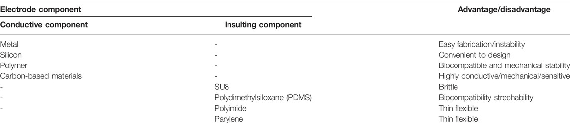
TABLE 1. Common materials and characteristics used for the preparation of conductive and insulating layers of the electrode.
The development of neuromorphic nanomaterials with high similarity to the characteristics of neural tissue, achieving seamless connection and functional fusion with neurons and having long-term effects on the brain, is expected in the future.
From the point of view of the design and use of the whole system, the distributed neural interface system similar to neurograin and can achieve high temporal resolution is the ideal neural technology.
Author Contributions
XL and BZ wrote this manuscript. CC drew the related figures. CD revised the overall manuscript.
Funding
This work was partly supported by the National Key R&D Program of China (2018YFA0701400) and Key Area R&D Program of Guangdong Province with grant No.2018B030338001.
Conflict of Interest
The authors declare that the research was conducted in the absence of any commercial or financial relationships that could be construed as a potential conflict of interest.
Publisher’s Note
All claims expressed in this article are solely those of the authors and do not necessarily represent those of their affiliated organizations, or those of the publisher, the editors, and the reviewers. Any product that may be evaluated in this article, or claim that may be made by its manufacturer, is not guaranteed or endorsed by the publisher.
References
Alexander, M. P. (1986). Principles of Neural Science. JAMA 255 (21), 3021. doi:10.1001/jama.1986.03370210189033
Asano, E., Juhász, C., Shah, A., Muzik, O., Chugani, D. C., Shah, J., et al. (2005). Origin and Propagation of Epileptic Spasms Delineated on Electrocorticography. Epilepsia 46 (7), 1086–1097. doi:10.1111/j.1528-1167.2005.05205.x
Blanche, T. J., Spacek, M. A., Hetke, J. F., and Swindale, N. V. (2005). Polytrodes: High-Density Silicon Electrode Arrays for Large-Scale Multiunit Recording. J. Neurophysiol. 93 (5), 2987–3000. doi:10.1152/jn.01023.2004
Campbell, P. K., Jones, K. E., and Normann, R. A. (1990). A 100 Electrode Intracortical Array: Structural Variability. Biomed. Sci. Instrum. 26, 161–165.
Chiang, C. H., Won, S. M., Orsborn, A. L., Yu, K. J., Trumpis, M., Bent, B., et al. (2020). Development of a Neural Interface for High-Definition, Long-Term Recording in Rodents and Nonhuman Primates. Sci. Transl. Med. 12 (538). doi:10.1126/scitranslmed.aay4682
Choi, J.-R., Kim, S.-M., Ryu, R.-H., Kim, S.-P., and Sohn, J.-W. (2018). Implantable Neural Probes for Brain-Machine Interfaces - Current Developments and Future Prospects. Exp. Neurobiol. 27 (6), 453–471. doi:10.5607/en.2018.27.6.453
Collinger, J. L., Wodlinger, B., Downey, J. E., Wang, W., Tyler-Kabara, E. C., Weber, D. J., et al. (2013). High-Performance Neuroprosthetic Control by an Individual with Tetraplegia. Lancet 381 (9866), 557–564. doi:10.1016/s0140-6736(12)61816-9
Desimone, R., Albright, T., Gross, C., and Bruce, C. (1984). Stimulus-Selective Properties of Inferior Temporal Neurons in the Macaque. J. Neurosci. 4 (8), 2051–2062. doi:10.1523/jneurosci.04-08-02051.1984
Hanson, T. L., Diaz-botia, C. A., Kharazia, V., Maharbiz, M. M., and Sabes, P. N. (2019). The “Sewing Machine” for Minimally Invasive Neural Recording. Preprint. doi:10.1101/578542
Huang, J., Laiwalla, F., Lee, J., Cui, L., Leung, V., Nurmikko, A., et al. (2019). A 0.01-mm2 Mostly Digital Capacitor-Less AFE for Distributed Autonomous Neural Sensor Nodes[J]. IEEE Solid-State Circuits Lett. 1, 162–165. doi:10.1109/LSSC.2019.2894932
Hubel, D. H., and Wiesel, T. N. (1959). Receptive Fields of Single Neurons in the Cat's Striate Cortex[J]. J. Physiology 148 (1), 574–591. doi:10.1113/jphysiol.1959.sp006308
Hubel, D. H. (1957). Tungsten Microelectrode for Recording from Single Units. Science 125 (3247), 549–550. doi:10.1126/science.125.3247.549
Jayakar, P., Gotman, J., Harvey, A. S., Palmini, A., Tassi, L., Schomer, D., et al. (2016). Diagnostic Utility of Invasive EEG for Epilepsy Surgery: Indications, Modalities, and Techniques. Epilepsia 57 (11), 1735–1747. doi:10.1111/epi.13515
Jun, J. J., Steinmetz, N. A., Siegle, J. H., Denman, D. J., Bauza, M., Barbarits, B., et al. (2017). Fully Integrated Silicon Probes for High-Density Recording of Neural Activity. Nature 551 (7679), 232–236. doi:10.1038/nature24636
Khodagholy, D., Gelinas, J. N., Thesen, T., Doyle, W., Devinsky, O., Malliaras, G. G., et al. (2015). NeuroGrid: Recording Action Potentials from the Surface of the Brain. Nat. Neurosci. 18 (2), 310–315. doi:10.1038/nn.3905
Lee, J., Laiwalla, F., Jeong, J., Kilfoyle, C., Larson, L., Nurmikko, A., et al. (2018). “Wireless Power and Data Link for Ensembles of Sub-mm Scale Implantable Sensors Near 1GHz[C],” in 2018 IEEE Biomedical Circuits and Systems Conference (BioCAS), Cleveland, OH, USA, 17-19 Oct. 2018 (IEEE).
Lee, J., Leung, V., Lee, A.-H., Huang, J., Asbeck, P., Mercier, P. P., et al. (2021). Neural Recording and Stimulation Using Wireless Networks of Microimplants. Nat. Electron 4 (8), 604–614. doi:10.1038/s41928-021-00631-8
Mal, N., Dimitrov, D., Carmena, J. M., Crist, R., Lehew, G., Kralik, J. D., et al. (2003). Chronic, Multisite, Multielectrode Recordings in Macaque Monkeys[J]. Proc. Natl. Acad. Sci. 100 (19), 11041–11046. doi:10.1073/pnas.1934665100
Martini, M. L., Oermann, E. K., Opie, N. L., Panov, F., Oxley, T., and Yaeger, K. (2020). Sensor Modalities for Brain-Computer Interface Technology: A Comprehensive Literature Review. Neurosurg. 86 (2), E108–E117. doi:10.1093/neuros/nyz286
Mcnaughton, B. L., O'Keefe, J., and Barnes, C. A. (1983). The Stereotrode: A New Technique for Simultaneous Isolation of Several Single Units in the Central Nervous System from Multiple Unit Records. J. Neurosci. Methods 8 (4), 391–397. doi:10.1016/0165-0270(83)90097-3
Moshayedi, P., Ng, G., Kwok, J. C. F., Yeo, G. S. H., Bryant, C. E., Fawcett, J. W., et al. (2014). The Relationship between Glial Cell Mechanosensitivity and Foreign Body Reactions in the Central Nervous System. Biomaterials 35 (13), 3919–3925. doi:10.1016/j.biomaterials.2014.01.038
Musk, E. (2019). Neuralink An Integrated Brain-Machine Interface Platform with Thousands of Channels. J. Med. Internet Res. 21 (10), e16194. doi:10.2196/16194
Newsome, W., and Pare, E. (1988). A Selective Impairment of Motion Perception Following Lesions of the Middle Temporal Visual Area (MT). J. Neurosci. 8 (6), 2201–2211. doi:10.1523/jneurosci.08-06-02201.1988
Normann, R. A. (2007). Technology Insight: Future Neuroprosthetic Therapies for Disorders of the Nervous System. Nat. Rev. Neurol. 3 (8), 444–452. doi:10.1038/ncpneuro0556
O'Keefe, J., and Dostrovsky, J. (1971). The hippocampus as a Spatial Map. Preliminary Evidence from Unit Activity in the Freely-Moving Rat. Brain Res. 34 (1), 171–175. doi:10.1016/0006-8993(71)90358-1
Owens, R. M., and Malliaras, G. G. (2010). Organic Electronics at the Interface with Biology. MRS Bull. 35 (6), 449–456. doi:10.1557/mrs2010.583
Pochay, P., Wise, K. D., Allard, L. F., and Rutledge, L. T. (1979). A Multichannel Depth Probe Fabricated Using Electron-Beam Lithography. IEEE Trans. Biomed. Eng. BME-26 (4), 199–206. doi:10.1109/tbme.1979.326558
Putzeys, J., Raducanu, B. C., Carton, A., De Ceulaer, J., Karsh, B., Siegle, J. H., et al. (2020). Neuropixels Data-Acquisition System: A Scalable Platform for Parallel Recording of 10 000+ Electrophysiological Signals. IEEE Trans. Biomed. Circuits Syst. 13 (6), 1635–1644. doi:10.1109/TBCAS.2019.2943077
Putzeys, J., Musa, S., Mora Lopez, C., Raducanu, B. C., Carton, A., De Ceulaer, J., et al. (2019). Neuropixels Data-Acquisition System: A Scalable Platform for Parallel Recording of 10 000+ Electrophysiological Signals. IEEE Trans. Biomed. Circuits Syst. 13 (6), 1635–1644. doi:10.1109/tbcas.2019.2943077
Rastogi, S. K., and Cohen-Karni, T. (2019). “Nanoelectronics for Neuroscience,” in Encyclopedia of Biomedical Engineering, 631–649. doi:10.1016/b978-0-12-801238-3.99893-3
Rubehn, B., Bosman, C., Oostenveld, R., Fries, P., and Stieglitz, T. (2009). A MEMS-Based Flexible Multichannel ECoG-Electrode Array. J. Neural Eng. 6 (3), 036003. doi:10.1088/1741-2560/6/3/036003
Sahasrabuddhe, K., Khan, A. A., Singh, A. P., Stern, T. M., Ng, Y., Tadić, A., et al. (2020). The Argo: A 65,536 Channel Recording System for High Density Neural Recording in Vivo. Preprint. doi:10.1101/2020.07.17.209403
Sscwartz, A. B. (2004). Cortical Neural Prosthetics. Annu. Rev. Neurosci. 27, 487–507. doi:10.1146/annurev.neuro.27.070203.144233
Stavrinidou, E., Leleux, P., Rajaona, H., Khodagholy, D., Rivnay, J., Lindau, M., et al. (2013). Direct Measurement of Ion Mobility in a Conducting Polymer. Adv. Mat. 25 (32), 4488–4493. doi:10.1002/adma.201301240
Steinmetz, N. A., Aydin, C., Lebedeva, A., Okun, M., Pachitariu, M., Bauza, M., et al. (2021). Neuropixels 2.0: A Miniaturized High-Density Probe for Stable, Long-Term Brain Recordings [J]. Science 372 (6539), eabf4588. doi:10.1126/science.abf4588
Tchoe, Y., Bourhis, A. M., Cleary, D. R., Stedelin, B., Lee, J., Tonsfeldt, K. J., et al. (2021). Human Brain Mapping with Multi-Thousand Channel PtNRGrids Resolves Novel Spatiotemporal Dynamics. Preprint.
Tooker, A., Tolosa, V., Shah, K. G., Sheth, H., Felix, S., Delima, T., et al. (2012). “Optimization of Multi-Layer Metal Neural Probe Design[J]. Conference Proceedings,” in Annual International Conference of the IEEE Engineering in Medicine and Biology Society, San Diego, CA, USA, 28 Aug.-1 Sept. 2012.
Tooker, A., Tolosa, V., Shah, K. G., Sheth, H., Felix, S., Delima, T., et al. (2012). “Polymer Neural Interface with Dual-Sided Electrodes for Neural Stimulation and Recording[C],” in International Conference of the IEEE Engineering in Medicine & Biology Society, San Diego, CA, USA, 28 Aug.-1 Sept. 2012 (IEEE), 5999–6002.
Vallabhaneni, A., Wang, T., and He, B. (2005). “Brain—Computer Interface [M],” in Neural Engineering (Boston, MA: Springer), 85–121. doi:10.1007/0-306-48610-5_3
Viventi, J., Kim, D.-H., Vigeland, L., Frechette, E. S., Blanco, J. A., Kim, Y.-S., et al. (2011). Flexible, Foldable, Actively Multiplexed, High-Density Electrode Array for Mapping Brain Activity In Vivo. Nat. Neurosci. 14 (12), 1599–1605. doi:10.1038/nn.2973
Wark, H. A. C., Sharma, R., Mathews, K. S., Fernandez, E., Yoo, J., Christensen, B., et al. (2013). A New High-Density (25 Electrodes/mm(2)) Penetrating Microelectrode Array for Recording and Stimulating Sub-millimeter Neuroanatomical Structures. J. Neural Eng. 10 (4), 045003. doi:10.1088/1741-2560/10/4/045003
Waschke, L., Kloosterman, N. A., Obleser, J., and Garrett, D. D. (2021). Behavior Needs Neural Variability. Neuron 109 (5), 751–766. doi:10.1016/j.neuron.2021.01.023
Wise, K. D., Angell, J. B., and Starr, A. (1970). An Integrated-Circuit Approach to Extracellular Microelectrodes. IEEE Trans. Biomed. Eng. BME-17 (3), 238–247. doi:10.1109/tbme.1970.4502738
Wise, K. D. (2005). Silicon Microsystems for Neuroscience and Neural Prostheses. IEEE Eng. Med. Biol. Mag. 24 (5), 22–29. doi:10.1109/memb.2005.1511497
Won, S. M., Song, E., Zhao, J., Li, J., Rivnay, J., and Rogers, J. A. (2018). Recent Advances in Materials, Devices, and Systems for Neural Interfaces. Adv. Mater 30 (30), e1800534. doi:10.1002/adma.201800534
Keywords: in vivo, neural interface, large scale, neural electrode, brain–machine interface
Citation: Zhang B, Deng C, Cai C and Li X (2022) In Vivo Neural Interfaces—From Small- to Large-Scale Recording. Front. Nanotechnol. 4:885411. doi: 10.3389/fnano.2022.885411
Received: 28 February 2022; Accepted: 28 April 2022;
Published: 28 June 2022.
Edited by:
Hui Fang, Dartmouth College, United StatesReviewed by:
Ki Jun Yu, Yonsei University, South KoreaSeung-Kyun Kang, Seoul National University, South Korea
Yi Qiang, Dartmouth College, United States
Copyright © 2022 Zhang, Deng, Cai and Li. This is an open-access article distributed under the terms of the Creative Commons Attribution License (CC BY). The use, distribution or reproduction in other forums is permitted, provided the original author(s) and the copyright owner(s) are credited and that the original publication in this journal is cited, in accordance with accepted academic practice. No use, distribution or reproduction is permitted which does not comply with these terms.
*Correspondence: Xiaojian Li, xj.li@siat.ac.cn