Plasmonic Nanostructures for Optically Induced Movement
 Sergio Balestrieri
 Gianluigi Zito1
  Giuseppe Coppola
- 1Institute of Science Applied and System Intelligence-National Research Council, Naples, Italy
- 2Dipartimento di Fisica, Università di Napoli Federico II, Napoli, Italy
Optical forces generated at the nanoscale using electric field gradients have proven to be a powerful tool for trapping and moving nano-objects in a variety of application fields ranging from aerospace engineering to biology and medicine. Typically, to achieve this optical effect plasmonic resonant cavities that combine localized surface plasmon resonances and propagative surface plasmon polaritons are used. Indeed, these structures allow to engineer the distribution of the excited field hotspots, so inducing a precise movement of the nanoparticles interacting with the plasmonic field. In this paper, starting from the theoretical analysis of the surface plasmons, the potentialities of plasmonic nanostructures are reviewed, analysing the geometric conformation designed according to the application. The configurations with the most interesting performance, among those mentioned in the literature, are described in detail, examining their main characteristics and limitations. Finally, the future development and prospects of these plasmonic nanostructures are discussed.
Introduction
The interaction of a light beam with a microscopic object can generate forces and torques, allowing manipulation even if the source of forces is at a considerable distance from the point of application. Each feature of the light (such as amplitude, phase, polarization, spatial distribution, etc) can induce surprising effect on the object manipulation. Absorption and scattering give rise to radiation pressure through the transfer of the linear momentum density of light. The momentum density, in turn, can be influenced by the angular momentum density of light spin (Ruffner and Grier, 2012) and/or gradients in the phase of the wavefronts (Roichman et al., 2008). Gradients in light intensity generate dipole forces that can be used for optically trapping a particle in a well-defined position. (Mansuripur, 2014). Properly structured light beams can transport small objects against the direction of propagation (Chen et al., 2011; Novitsky et al., 2011; Wang et al., 2013).
In this article, we analyze the advantages of generating a force on small objects using surface plasmonic nanostructures that enhance the optical radiation features. Indeed, the design of the surface plasmons, that is the excitation resulting from the resonant interaction in a structure composed of a metal on a dielectric substrate, allows to generate an electromagnetic field with appropriately structured characteristics, such as: concentration of high energies in small areas (beyond the diffraction limit), uniform or non-uniform spatial amplitude distribution, polarisation-dependent behaviour, and so on. Plasmonic structures are capable of inducing forces for the manipulation of small objects; in this review we will focus on the dynamics generated by these structures. In particular, we will observe that nanoparticles placed in proximity to a metal structure capable to excite a plasmonic phenomenon can induce small displacements around an equilibrium point. Moreover, it is also possible to design particular metal structures that generate an appropriate electric field distribution capable of inducing a propulsion. The latter capability could be very useful in new emerging applicative sectors such as medical-biological or space applications. Indeed, with the recent development of micro- and nanosatellites, interest in propulsion driven by a remote optical source has increased. The nanoplasmonic approach could allow generating a micro/nanosatellite propulsion without the need to add power on the satellite, unlike the classical approach (such as chemical or electric propulsion (Gassend et al., 2009; Sathiyanathan et al., 2011; Cervone et al., 2016; Lemmer, 2017; Tummala and Dutta, 2017). To provide a self-consistent understanding of the potential of plasmonic nanostructures for optically induced motion, the rest of the paper is organized as follows: in the first section, the theoretical principles of plasmon-enhanced light–matter interactions are discussed, highlighting the phenomena to be exploited for force generation. In the second chapter, the optical trapping is reviewed, starting from Askin’s method and analyzing the advantages of using plasmonic nanostructures in generate static or dynamic equilibrium. In the third chapter, nanostructures able of generating force fields for long-range particle motion are reported. In addition, some applications and the relative induced thrust parameters, are illustrated. Finally, conclusions and some future perspectives are presented.
Theoretical Principles
In this section, we will analyse how, from a theoretical point of view, a force can be generated by an electromagnetic field of an optical radiation and which optically induced phenomena allow the amplification of this force. Given an electromagnetic wave, whose associated fields can be described by means of Maxwell’s equations, and an object located inside the light beam, it is possible to define the Maxwell stress tensor as a tensor that encloses all the momentum per unit time resulting from the interaction of the object with the electromagnetic fields, i.e., (Novothny and Hecht, 2006):
Where
It is possible from Maxwell’s stress tensor to derive the force applied to an object resulting from the interaction with electromagnetic fields as described (Novothny and Hecht, 2006):
Where
If the dimensions of the object are much smaller than the wavelength of the incident beam, some approximations (described in (Novothny and Hecht, 2006)) in the resolution of the Maxwell’s tensor can be applied. So the force term reported in equation (Eq. 2) can be redefined in the following way:
Where
Because of these behaviours, gradient forces are commonly used in the literature to develop structures capable of inducing motion in particles, and this means designing structures capable of generating fields of non-uniform amplitude. Among the various approaches described in the literature (Soukoulis, 2002; Fujimaki et al., 2008) to generate electric fields with a spatial distribution of non-uniform amplitude, one of the most effective is surface plasmonics. This phenomenon occurs when an electromagnetic wave irradiates an interface between a metallic material and a dielectric material (Maier, 2007). Surface plasmonics manifests itself in two different ways called Surface Plasmons Polaritons (SPP) and Localized Surface Plasmon (LSP).
This phenomenon related to coherent oscillations of delocalised electrons occurs when an electromagnetic wave radiates an interface between a metallic material and a dielectric material. In fact, when light and freely moving electrons (as in a metal) interact, the oscillating electric-magnetic field of the light forces the free electrons to move together with the electromagnetic oscillations. This movement of electrons produces an additional electromagnetic field. Two types of surface plasmonics can be considered: Surface Plasmons Polaritons (SPP) and Localized Surface Plasmons (LSP).
SPPs are waves that propagate along the metal-dielectric interface and are highly localised, indeed the electric field in the direction orthogonal to the interface is evanescent. To obtain an SPP analytically, the Maxwell’s equations on an interface between a metal (
where
In order to generate an SPP, the x-long component of the momentum of the free photon (
On the other hand, Localized Surface Plasmon are non-propagating excitations of conduction electrons relative to metallic nanostructures coupled to the electromagnetic field. LSPs are derived from Mie theory, assuming that the nanostructure has spatial dimensions much smaller than the wavelength of the incident beam (quasi-static field approximation) (Maier, 2007). This assumption implies that the equations of electrostatics, i.e., Laplace’s equations, can be used in the evaluation of the electric field. Once solved, a polarizability in the following form is obtained:
Where V is the volume of the nanostructure. Thus, for polarizability can be determined a resonance (
Thus, at resonance there is an amplification of electromagnetic fields.
In addition, unlike SPPs, there are no conditions limiting the generation of a LSP, so direct illumination can also be used.
Plasmonic Force Confinement
In the previous chapter, it was explained from a theoretical point of view how a force can be generated from an electromagnetic field, and that in order to obtain intense forces, the mechanisms of surface plasmonics can be used, which allow electric fields with high amplitudes and non-uniform spatial distribution to be achieved. This chapter describes how surface plasmonics phenomena can be induced by nanostructures suitably designed to achieve the desired electric field distributions.
A typical example are optical tweezers, structures capable of trapping particles and keeping them in stable equilibrium at a given location in space. Historically, optical tweezers were proposed by Askin (Mansuripur, 2014) in 1970. Their operation in a macroscopic case is defined as follows: A spherical particle of dielectric material (index of refraction
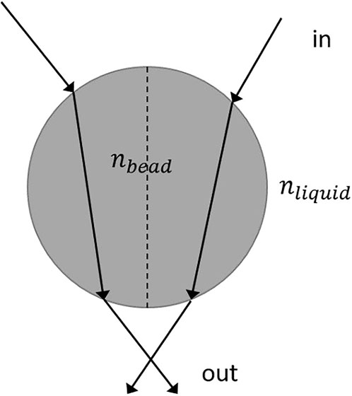
FIGURE 1. Optical trapping method used by Askin.
Moreover, if the particle is moved sideways relative to the equilibrium point, a pullback force is generated that returns the particle to its original position, making the equilibrium stable.
If the particle size is reduced to the order of microns or less, Askin’s method is unable to maintain the stable equilibrium of the particle due to effects that disturb its effectiveness (Juan et al., 2011); in particular:
• The reduction of the pullback force related to its dependence on the volume of the particle.
• The reduction in viscous friction due to the dependence on the surface area of the particle.
• The effect of temperature, which rises when the particle is microscopic, and thus generating chaotic motions around the equilibrium point, delocalising the particle.
An increase in the intensity of the incident laser beam can be used to mitigate the delocalization effect and other microscopic effects.
The main limitation of this technique is related to the size of the particles. When this latter reaches a value close to half the wavelength of the incident beam, diffractive effects appear which tend to disperse the beam of light and prevent it from focusing on the particle.
There are some techniques that can overcome the limitations associated with diffractive effects. For example, optoelectronic tweezers (Wu, 2007), in which light creates virtual electrodes and therefore, by coupling with a non-uniform electric field, generates a region in which the particles are confined. A similar effect is achieved with the opto-thermophoretic tweezers technique (Zheng et al., 2018), which creates a temperature gradient by optical heating, allowing for manipulation of displacement and trapping of particles.
These techniques allow to have a good control on micro and nanoparticles, even if the trapping will be extremely weak; on the other hand, Surface Plasmons Polaritons (Shuller et al., 2010; Juan et al., 2011; Daly et al., 2015) generate extremely concentrated fields beyond the diffractive limit, succeeding to trap a nanoparticle with extreme efficiency, however, making some dynamic operations more complex than in previous cases, in which they were easily performed.
In general, when a plasmonic optical tweezer is irradiated by an electromagnetic wave at resonance frequency, a symmetrical field distribution (hotspot) is generated in a specific area of the structure such that the resulting forces tend to trap the nanoparticles in the centre of the hotspot. A typical example of a plasmonic optical tweezer is shown in (Yang et al., 2011) (Figure 2), where a cylindrical silicon waveguide is placed at a distance (g) from a metallic substrate.
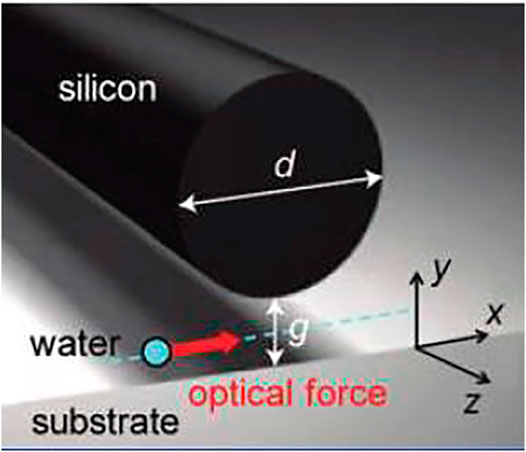
FIGURE 2. Image showing the silicon waveguide separated by a sub-micrometer gap to a metal substrate, showing the optical force applied to the nanoparticles (Complete with permission from Yang et al. (2011). Copyright 2011 American Chemical Society).
When the system is illuminated from the z axis, an electric field hotspot is generated in the space between the guide and the metal substrate, and the associated force is such that the nanoparticles are trapped in this gap.
In addition to generating symmetrical field distributions that tend to lock the nanoparticles at a defined point, plasmonic optical tweezers can also be designed to achieve equilibrium dynamically. That is, generating a stationary movement around a given point. An example of this type of structure is described in (Huft et al., 2017) and illustrated in Figure 3A, where an optical tweezer is constructed using a plasmonic bull’s eye configuration to transform the incident wave into converging plasmonic waves.
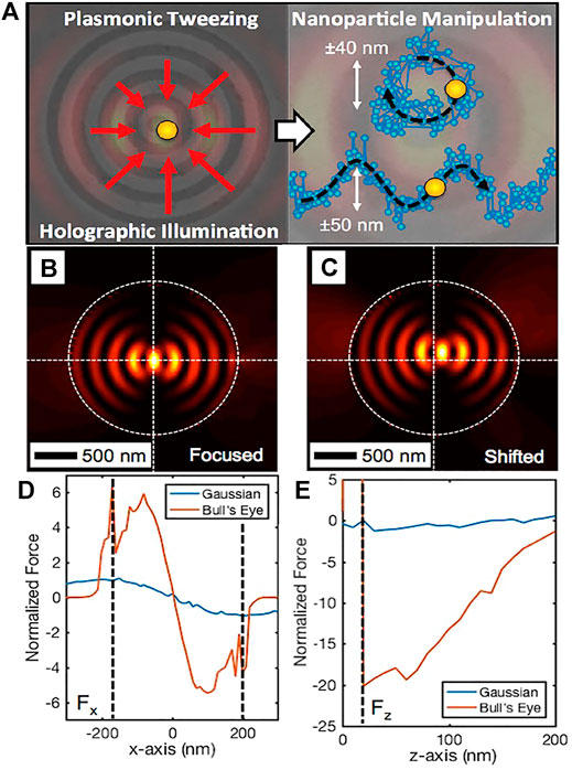
FIGURE 3. (A) the plasmonic bull’s eye with the direction of the plasmonic waves used to trap the particle in the centre and some trajectories that can be generated with time-dependent beams; (B) centred hot spot simulated with equation (Eq. 9); (C) shifted phase profile hot spot simulated with equation (Eq. 9); (D) Normalized Force plot for a Bull’s Eye device and a conventional optical tweezers for x-component Force.; (E) Normalized Force plot for a Bull’s Eye device and a conventional optical tweezers for z-component force. (Complete with permission from Huft et al. (2017). Copyright 2017 American Chemical Society).
In order for the particles to be trapped in the centre of the structure, the plasmonic waves have to interfere constructively in the centre and to achieve this effect, a phase shift of π is required in the generation of the various SPPs. This implies that it is necessary to modulate the beam in such a way that the interference of the various SPPs occurs at different positions from the centre of the structure. To achieve this, the phase function (
Where a is the period of the Bull’s eye pattern which is chosen equal to the wavelength of the SPP at the interface between silver and water. To verify this behaviour, the authors carried out some simulations using COMSOL Multiphysics (Huft et al., 2017) in which the plasmonic ring was modelled assuming a set of sources along the ring with a field defined as:
Where
The simulations show that hot-spots (Figures 3B,C) are formed whose position depends on the phase of the incedent beam, confirming the assumptions defined above. Figure 3D shows the difference between the x-long components of the resulting forces in a Bull’eye device case (orange) compared to a conventional optical tweezer (blue). It can be seen that the force generated by the Bull’s Eye is much more intense than in the conventional case; the same result is also obtained if we compare (see Figure 3E) the components along z of the forces of the Bull'Eye (orange) with respect to the conventional case (blue). For this reason, the plasmonic Bull’s Eye has more effective trapping than the conventional case.
Moreover, the results shown that using a beam with a time-varying phase, the trapping site moves, generating a motion of the nanoparticle. The motions obtained are such as to generate either linear trajectories along a specific direction, or circular trajectories (some examples are shown in Figure 3A).
Liaw et al. (2018) proposed another particular case of a plasmonic optical tweezer with dynamic equilibrium obtained using an array of gold dimers separated by a gap (see Figure 4). These are irradiated by a polarised field along x, generating forces and relative moments on polystyrene nanoparticles in the vicinity of the system.
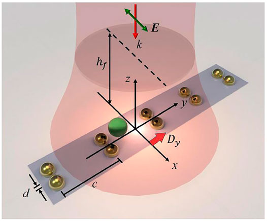
FIGURE 4. Configuration of a 1D gold dimer array trapping a nanoparticle using a normally incident Gaussian beam. The dimer gap, lattice constant and displacement along y are denoted respectively by
In Figure 5A can be seen the optical force generated by the system; to achieve the equilibrium this optical force is compensated by the friction force generated by the liquid in which the nanoparticles are immersed. Two types of equilibrium can be generated: a contact equilibrium in which the nanoparticles tend to adhere to a gold dimer, and a non-contact equilibrium in which the dimers generate a swirling motion around a point in space known as the stagnation point. The resulting moments are the combination of the angular momentum generated by the Maxwell tensor and the momentum generated by friction with the liquid. In Figure 5B illustrates the generation of two nanoparticle spins, the direction of which depends on the vortex’s torsion. In particular, if the vortex rotates clockwise (Figure 5A), there will be an anti-clockwise nanoparticle spin (Figure 5B), whereas if the vortex rotates anti-clockwise (Figure 5A), there will be a clockwise nanoparticle spin (Figure 5B). Moreover, the results show that if the dimer array is moved away from the focal point of the beam, the nanoparticles initially tend to follow the array (Liaw et al., 2018). However, there is a threshold length which, if exceeded, generates an additional vortex leading to trapping of the nanoparticles away from the dimeric matrix. Finally, since these structures are plasmonic in nature, it is also possible to obtain an increase in vortex intensity by reducing the distance or gap between the dimers.
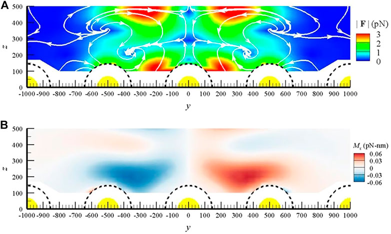
FIGURE 5. (A) Optical vortices manifested in a streamline map of the optical force field. In particular, this streamline map depicts the field of forces (
Plasmonic Optical Thruster
In the previous paragraph it was reviewed how optical tweezers can produce symmetrical field distributions such that the resulting forces are able to keep a nanoparticle in equilibrium, while in the following a number of proposals for achieving a long-range movement of nanoparticle will be presented. There is the possibility of obtaining thrust forces using radiation-matter interaction effects; in particular, we mention solar sail (Swartzlander, 2017), (Davis and Mead, 2011), laser ablation (Sasoh, et al., 2017) and the thermo-optical effect observed in (Ndukaife et al., 2015). In this paragraph, however, we will observe that it is possible to induce a long-range force in microscopic objects by means of a gradient force induced by specific field distributions. It will also be shown that this effect is achieved very effectively thanks to surface plasmonic phenomenon.
A simple plasmonic device has been presented in (Wang et al., 2009), consisting of a metal layer placed on the base of a prism with the tip pointing downwards (this type of solution is also known as the Kreshmann configuration (Maier, 2007) see Figure 6). Gold nanoparticles are placed on this structure in aqueous solution. If the particles are free from any constraint they tend to move only for thermal effects. These effects generate a chaotic motion (Brownian motion) in all directions of space. When an incident beam illuminates the prism at a certain angle, nanoparticles tend to acquire a drift velocity in the direction parallel to the air-metal interface (x-axis) and in the direction orthogonal to it (z-axis); this is sketched in Figure 6.
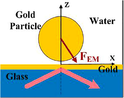
FIGURE 6. Interface of plasmonic coupling with gold nanoparticle (xz plane) (Complete with permission from Wang et al. (2009). Copyright 2009 American Chemical Society).
However, the drift only occurs if the incident beam has a TM polarization. This suggests that the cause of the drift phenomenon is attributable to the formation of an SPP. The hypothesis is confirmed by the contextual observation of a chaotic motion along the y-axis. In fact, the SPPs are such that they generate field distributions only along the interface and orthogonal to the interface (see Figure 6) so this implies that forces are obtained only along the two aforesaid directions, leaving the y-axis free from any constraint. Figure 7 presents the results of the analysis of the optical forces (and the induced velocity) acting on the nanoparticles, as function either of the distance between the metal surface and the aqueous solution and the intensity of the optical beam.
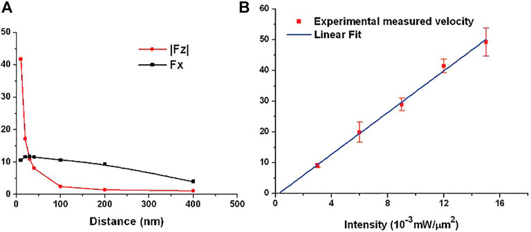
FIGURE 7. (A) The components of the optical force applied to the nanoparticle as a function of the distance between the particle and the metal substrate. (B) The velocity of the particle measured as the intensity of the incident beam changes. Complete with permission from Wang et al. (2009). Copyright 2009 American Chemical Society.
In particular, it has been observed that as the intensity of the incident beam increases, the drift speed tends to increase, implying that the optical force also increases as the intensity increases. On the other hand, as the distance between the metal and the nanostructures increases, the force tends to decrease, with different behaviour depending on the force component observed. In fact, the force along z tends to decay exponentially as the distance varies, while that along x decays in an almost linear manner. Finally, the authors performed a comparison between the propulsion generation obtained through the formation of an SPP, and that obtained through total internal reflection, i.e., using the same structure but without the metal layer. The results show that the fields obtained by SPP are much more intense, although they can only be used if the excitation beam illuminates the structure at the right resonance angle.
A more complex configuration capable of generating propulsion with an output speed that can be used for medical-biological applications is well explained in (Søndergaard et al., 2010; Shalin and Sukhov, 2013). The structure, as can be seen in Figure 8, consists of a V-shape cavity made of a gold film deposited on a glass substrate.
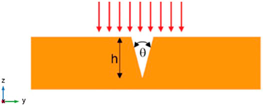
FIGURE 8. Sketch of the V-shape plasmonic structure, illuminated by a TM-polarized light. Complete with permission of Søndergaard et al. (2010). Copyright 2010 American Chemical Society.
When the structure is irradiated with TM-polarized light, an intense electric field is generated at the bottom of the trench; this is due to the generation of a resonant LSP. Once the resonance is excited, two SPPs are formed along the edges of the structure by near field excitation. The coupling of the two Surface Plasmon implies a significant amplification of the field. The amplification factor is a function of the geometrical parameters and in particular an increase can be obtained if the angle (
where
Numerical simulations (Shalin and Sukhov, 2013) were carried out on the structure and the velocity of a silver nanoparticle with a radius of 8 nm was estimated. The estimated velocity is 0.1 m/s when illuminating the plasmonic structure by a TM-polarized wave having a power density of 1–2
Rovey’s group has designed a plasmonic structure that allows higher values of thrust and velocity: (Rovey et al., 2015; Jiao et al., 2016; Maser et al., 2016; Zhang et al., 2019). This is not due to an increase in the force generated by the single structure, but to the possibility of being able to couple a large number of elementary structures in such a way as to form an array and thus obtain a force resulting from the sum of the elementary contributions related to the single structures. Thus, the total force is greatly amplified and can be used in numerous applications, including space propulsion. The system (see Figure 9) consists of two trapezoidal gold structures separated by a gap and deposited on a glass substrate.
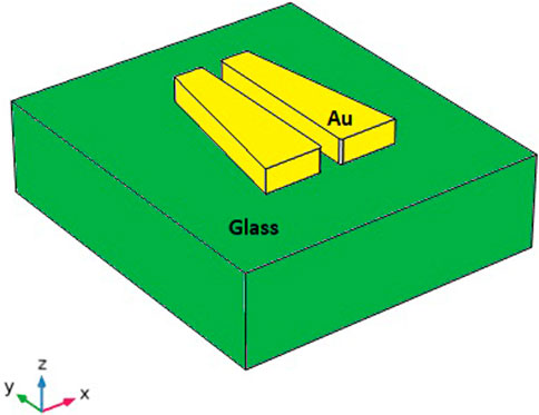
FIGURE 9. Sketch of the asymmetrical trapezoidal plasmonic structure. Adapted from Jiao et al. (2016)
When the structures are uniformly illuminated, a resonance, due to the generation of an LSP, is formed in the gap between the two trapezoids. The resonance wavelength depends on the geometrical parameters of the gold structures, i.e. the width of the two bases of the trapezium, its length, its thickness and the gap. Once the resonance has been induced, the near-field excitation forms two SPPs along the edges of the two trapezoids that couple within the gap and, as in the structure discussed in the previous paragraph, generate a strongly amplified and asymmetric field distribution. By calculating the forces through the Maxwell tensor (Eq. 1), we obtain a distribution that depends on the position along y of the system (see Figure 10A), such that a nanoparticle undergoes a strong initial acceleration followed by a deceleration zone of lesser intensity (see Figure 10B).
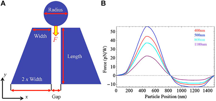
FIGURE 10. (A) A cut in the xy plane of the trapezoidal structure, showing the direction of the ejection force; (B) the graph of the force as the y coordinate of the nanoparticle changes. Adapted from Rovey et al. (2015).
Preliminary experimental results for this configuration are also reported in refs. (Rovey et al., 2015; Jiao et al., 2016; Maser et al., 2016; Zhang et al., 2019), confirming the functionality expected from theory and simulations. In general, it is observed that structures with larger horizontal asymmetries (i.e., along the y-axis) have more amplified electric fields. Therefore, in order to induce further asymmetry, the oblique side of the trapezoid can be modified in a stepwise manner.
Figure 11 shows a comparison of the field distribution between a trapezoidal structure with linear and stepped oblique sides (Zhang et al., 2019).
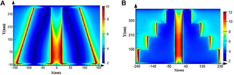
FIGURE 11. (A) Electric field distribution in a trapezoidal structure the wave is polarised along x at wavelength 532 nm; (B) electric field distribution of a modified oblique-sided trapezoidal structure with the wave polarised along x and at wavelength 580 nm. © 2019 IEEE. Reprinted, with permission, from Zhang et al. (2019).
As mentioned above, in general, the output speed induced by a single plasmonic structure is relatively low. In order to obtain more efficient performance useful for practical applications, an array of the above elementary structures can be constructed by organising an array through a so-called end-to-end configuration (Figure 12A). In this configuration, the minor base of a trapezoid is adjacent to the major base of the next structure. Using this spatial configuration, it is possible to obtain a continuous sequence of pushes on the nanoparticle, which implies a considerable increase in the force applied and, consequently, in the output speed.
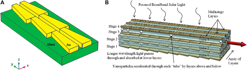
FIGURE 12. (A) A sketch of the array configuration in end-to-end mode; (B) the thruster hypothesised in Rovey et al. (2015) to make full use of sunlight. Adapted from Rovey et al. (2015).
The plasmonic structure was arranged in a multilayer array configuration, where each layer has a different resonance wavelength, to function properly even with broadband illumination such as solar radiation (Rovey et al., 2015) (see Figure 12B). In fact, with this approach, each layer of the stack is able to utilise a specific part of the solar spectrum, increasing the overall efficiency. The nanoparticles are contained in nano-channels between the active layers, so that the resulting force applied to the nanoparticles will be a combination of the forces obtained from the arrays above and below each channel.
Thanks to its estimated performance, this plasmonic configuration has been proposed as a thruster for space applications. The values of thrust, specific impulse and ejection velocity of a nanoparticle for the thruster based on the multilayer array configuration are estimated using the following relationships:
where m is the mass of the nanoparticle, N is the number of arrays in a single layer (the number of rows in Figure 12B), f is the ejection rate of the nanoparticle, L is the acceleration length, and
However, as can be seen in Figure 13, the array presents a potential limitation (Rovey et al., 2019), namely when the elementary structures are organised in array with an end-to-end configuration, the distribution of the field supported by the plasmonic structure changes compared to the case of the isolated elementary structure, and with it, obviously, the spatial distribution of the force acting on the nanoparticles also changes. In fact, in the array configuration, the distribution of forces is such that the particle must overcome a potential barrier to pass from one elementary structure to the next. The intensity of this potential barrier is such that the kinetic energy of the particle is not sufficient to allow its overcoming in the short space in which the particle acquires velocity. For this reason, the particle needs an additional initial thrust that is sufficiently high to allow it to overcome the potential barrier and continue its motion.
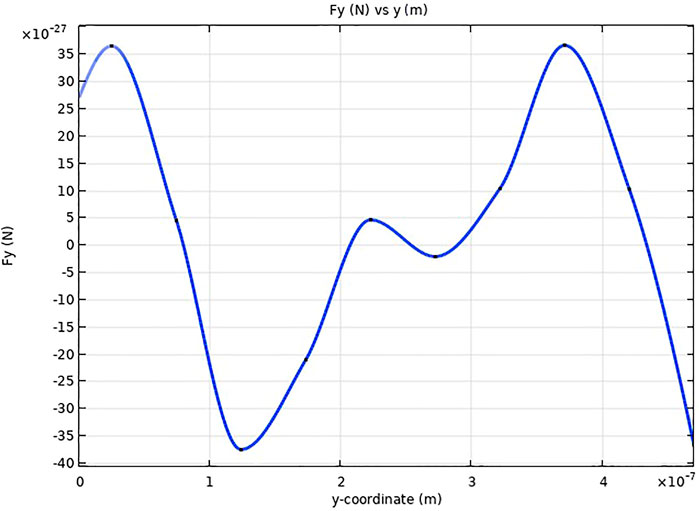
FIGURE 13. Y-component of the force applied to a glass particle of radius 50 nm as a function of the y-coordinate of a set of trapezoidal structures as in Rovey et al. (2015), placed in an end-to-end configuration with the following parameters: height 350 nm, major base 120 nm, minor base 60 nm, gap 40 nm, thickness 50 nm. The light is polarized along x and at wavelength 730 nm and the amplitude of the incident electric field is such that it is normalized.
Conclusion
The growing demand for the manipulation of microscopic objects using long-range techniques has increasingly required the development of techniques capable of spatially intensifying and concentrating electromagnetic fields with the aim of improving the electromagnetic forces acting on objects. In this context, one of the most interesting techniques is based on the use of the surface plasmonics phenomena that have the capability to amplify the electric field in areas much smaller than the diffractive limit. Research in recent years has been trying to exploit this ability of surface plasmonics to realize structures that can control the motion and trajectory of a nanoparticle. Properly designed plasmonic structures have been conceived and characterised to generate hotspots, i.e., symmetrical field distributions, such that the resulting forces are able to trap particles in a specific spatial region. Thanks to the potential of plasmonic structures to engineer the spatial distribution of generated electromagnetic fields, plasmonic phenomena are recently being studied to induce also studied to induce long-range movement of nanoparticles. Some interesting applications have already been imagined for these structures, such as the transport of molecules and genetic material within cells or the propulsion of micro/nanosatellites. The latter appears to be particularly fascinating and in fact there are already a good number of publications on the optimisation of usable configurations. However, there are still limitations to the practical and efficient use of these structures; in particular, the presence of a potential barrier which inhibits the achievement of a large exit velocity. To address this limitation, a new design of the structure or, as already demonstrated for dynamic optical tweezers, a suitable modification of the incident beam could be useful. It is therefore clear that resonant plasmonic structures, due to their properties and design versatility, are an interesting field of research for the induction of microscopic particle motion by light radiation and in particular for the development of future optical propulsion techniques useful for the next generation of micro/nanosatellite constellations.
Author Contributions
GC and MI conceived the idea of the paper. SB and GZ formalized the theoretical section. SB detailed the optical tweezer section. GC, MI and SB described the plasmonic propulsion section. All the authors analyzed the data and made additional effort in preparing the paper.
Funding
“PON ARS01_01181 PM3—Multi Mission Modular Platform” Industrial Research and Experimental Development Projects in the 12 areas of specialisation identified by the National Research Programme 2015-2020—CUP B66G18000740005.
Conflict of Interest
The authors declare that the research was conducted in the absence of any commercial or financial relationships that could be construed as a potential conflict of interest.
Publisher’s Note
All claims expressed in this article are solely those of the authors and do not necessarily represent those of their affiliated organizations, or those of the publisher, the editors and the reviewers. Any product that may be evaluated in this article, or claim that may be made by its manufacturer, is not guaranteed or endorsed by the publisher.
References
Cervone, A., Zandbergen, B., Guerrieri, D. C., De Athayde Costa e Silva, M., Krusharev, I., and van Zeijl, H. (2016). Green Micro-Resistojet Research at Delft University of Technology: The New Frontiers. CEAS Space J. 9 (1), 111–125. doi:10.1007/s12567-016-0135-3
Chen, J., Ng, J., Lin, Z., and Chan, C. (2011). Optical Pulling Force. Nat. Photon. 5, 531–534. doi:10.1038/nphoton.2011.153
Daly, M., Sergides, M., and Chormaic, S. N. (2015). Optical Trapping and Manipulation of Micrometer and Submicrometer Particles. Laser Photon. Rev 9 (3), 309–329. doi:10.1002/lpor.201500006
Fujimaki, M., Rockstuhl, C., Wang, X., Awazu, K., Tominaga, J., Fukuda, N., et al. (2008). The Design of Evanescent-Field-Coupled Waveguide-Mode Sensors. Nanotechnology 19, 095503. doi:10.1088/0957-4484/19/9/095503
Gassend, B., Velásquez-García, L. F., Akinwande, A. I., and Martínez-Sánchez, M. (2009). A Microfabricated Planar Electrospray Array Ionic Liquid Ion Source with Integrated Extractor. J. Microelectromechanical Syst. 18 (3), 679–694. Available at: http://hdl.handle.net/1721.1/59347. doi:10.1109/jmems.2009.2015475
Huft, P. R., Kolbow, J. D., Thweatt, J. T., and Lindquist, N. C. (2017). Holographic Plasmonic Nanotweezers for Dynamic Trapping and Manipulation. Nano Lett. 17, 7920–7925. doi:10.1021/acs.nanolett.7b04289
Jiao, J., Lin, E., Gaofeng, L., and Zhao, Q. (2016). “Nano Optical Propeller Based on Localized Field Intensity Enhancement of Surface Plasmons,” in SPIE. Chengdu, China, Yongkun Ding. doi:10.1117/12.2268294
Juan, M. L., Rrighini, M., and Quidant, R. (2011). Plasmon Nano-Optical Tweezers. Nat. Photon. 5, 349–356. doi:10.1038/nphoton.2011.56
Lemmer, K. (2017). Propulsion for CubeSat. Acta Astronautica 134, 231–243. doi:10.1016/j.actaastro.2017.01.048
Li, J., Lin, L., Inoue, Y., and Zheng, Y. (2018). Opto-Thermophoretic Tweezers and Assembly. J. Micro- Nano-Manufactoring 6, 040801. doi:10.1115/1.4041615
Liaw, J.-W., Chien, C-W., Liu, K-C., Ku, Y-C., and Kuo, M-K. (2018). 3D Optical Vortex Trapping of Plasmonic Nanostructure. Scientific Rep. 8, 12673. doi:10.1038/s41598-018-30948-y
Mansuripur, M. (2014). “Mechanical Effects of Light on Material Media: Radiation Pressure and the Linear and Angular Momenta of Photons,” in SPIE at The University of Arizona, Tucson, US, Harrison H. Barret. doi:10.1117/12.2063432
Maser, J. N., Li, L., Deng, H., Yang, X., and Rovey, J. L. (2016). Transmission Spectrum of Asymmetric Nanostructures for Plasmonic Space Propulsion. J. Spacecraft Rockets 53 (5), 998–1000. doi:10.2514/1.A33576
Ndukaife, J. C., Kildishev, A. V., Nnanna, A. G. A., Shalaev, V. M., Wereley, S. T., and Boltasseva, A. (2015). Long-Range and Rapid Transport of Individual Nano-Objects by a Hybrid Electrothermoplasmonic Nanotweezer. Nat. Nanotechnologies 11 (1), 53–59. doi:10.1038/NNANO.2015.248
Novitsky, A., Qiu, C.-W., and Wang, H. (2011). Single Gradientless Light Beam Drags Particles as Tractor Beams. Phys. Rev. Lett. 107 (20), 203601. doi:10.1103/PhysRevLett.107.203601
Novothny, L., and Hecht, B. (2006). Principles of Nano-Optics. I ed. New York: Cambridge University Press.
Roichman, Y., Sun, B., Roichman, Y., Amato-Grill, J., and Grier, D. G. (2008). Optical Forces Arising from Phase Gradients. Phys. Rev. Lett. 100, 013602. doi:10.1103/PhysRevLett.100.013602
Rovey, J. L., Friz, P. D., Hu, C., Glascock, M. S., and Yang, X. (2015). Plasmonic Force Space Propulsion. J. Spacecraft Rockets 52 (4), 1163–1168. doi:10.2514/1.A33155
Rovey, J. L., Joshua, L., and Jie, G. (2019). Experimental Demonstration and System Analysis for Plasmonic Force Propulsion. No. HQ-E-DAA-TN75812.: Nasa Report.
Ruffner, D., and Grier, D. (2012). Optical Forces and Torques in Non Uniform Beams of Light. Phys. Rev. Lett. 108, 173602. doi:10.1103/PhysRevLett.108.173602
Sasoh, A., Tsuruta, H., Katagiri, Y., Dondelewski, O., and Wang, B. (2017). Characteristics of Ablation Impulse Induced by Repetitive Laser Pulse Irradiations. Darmstadt, Germany: T. Flohrer; F. Schmitz.
Sathiyanathan, K., Lee, R., Chesser, H., Dubois, C., Stowe, R., Farinaccio, R., et al. (2011). Solid Propellant Microthruster Design for Nanosatellite Applications. J. Propulsion Power 27 (6), 1288–1294. doi:10.251/1.B34109
Shalin, A. S., and Sukhov, S. V. (2013). Plasmonic Nanostructures as Accelerators for Nanoparticles: Optical Nanocannon. Plasmonics 8, 625–629. doi:10.1007/s11468-012-9447-0
Shuller, J. A., Barnard, E. S., Cai, W., Jun, Y. C., White, J. S., and Brongersma, M. L. (2010). Plasmonic for Extreme Light Concentration and Manipulation. Natur. Mater. 9, 193–204. doi:10.1038/nmat2630
Søndergaard, T., Bozhevolnyi, S. I., Beermann, J., and Novikov, S. M. (2010). Resonant Plasmon Nanofocusing by Closed Tapered Gaps. Nano Lett. 10, 291–295. doi:10.1021/nl903563e
Soukoulis, C. M. (2002). The History and a Review of the Modeling and Fabrication of Photonic Crystal. Nanotechnology 13 (3), 420. doi:10.1088/0957-4484/13/3/335
Swartzlander, J. G. A. (2017). Radiation Pressure on a Diffractive Sailcraft. J. Opt. Soc. America B 34 (6), C25–C30. doi:10.1364/josab.34.000c25
Tummala, A. R., and Dutta, A. (2017). An Overview of Cube-Satellite Propulsion Technologies and Trends. Aerospace 4, 58. doi:10.3390/aerospace4040058
W. Davis, E., Franklin, B., and Mead, J. (2011). Review of Laser Lightcraft Propulsion System. American Istitute of Physics, Mariland, US, A.V. Pakhomov.
Wang, K., Schonbrun, E., and Crozier, K. B. (2009). Propulsion of Gold Nanoparticles with Surface Plasmon Polaritons: Evidence of Enhanced Optical Force from Near-Field Coupling Between Gold Particle and Gold Film. Nano Lett. 9 (7), 2623–2629. doi:10.1021/nl900944y
Wang, N., Chen, J., Liu, S., and Lin, Z. (2013). Dynamical and Phase-Diagram Study on Stable Optical Pulling Force in Bessel Beams. Phys. Rev. A. 87, 063812. doi:10.1103/physreva.87.063812
Wu, M. C. (2007). “Optoelectronic Tweezers for Nanomanipulation,” in 2007 International Nano-Optoelectronics Workshop, Bejing, China, 29 July-11 Aug. 2007 (IEEE). doi:10.1109/INOW.2007.4302858
Yang, X., Liu, Y., Oulton, R. F., Yin, X., and Zhang, X. (2011). Optical Forces in Hybrid Plasmonics Waveguides. Nano Lett. 11, 321–328. doi:10.1021/nl103070n
Keywords: plasmonic structures, optical force, photokinetic, optical propulsion, nanostructures
Citation: Balestrieri S, Zito G, Coppola G and Iodice M (2022) Plasmonic Nanostructures for Optically Induced Movement. Front. Nanotechnol. 4:886636. doi: 10.3389/fnano.2022.886636
Received: 28 February 2022; Accepted: 04 April 2022;
Published: 05 May 2022.
Edited by:
Carlo Rizza, University of L'Aquila, ItalyReviewed by:
Arindam Dasgupta, Missouri University of Science and Technology, United StatesLinhan Lin, Tsinghua University, China
Copyright © 2022 Balestrieri, Zito, Coppola and Iodice. This is an open-access article distributed under the terms of the Creative Commons Attribution License (CC BY). The use, distribution or reproduction in other forums is permitted, provided the original author(s) and the copyright owner(s) are credited and that the original publication in this journal is cited, in accordance with accepted academic practice. No use, distribution or reproduction is permitted which does not comply with these terms.
*Correspondence: Sergio Balestrieri, sergio.balestrieri@na.isasi.cnr.it
†These authors have contributed equally to this work and share senior authorship