Key results from examinations of seven high burnup pressurized water reactor spent nuclear fuel rods
 Rose Montgomery
 Bruce Bevard
  Paul Cantonwine
 Yadukrishnan Sasikumar
- Oak Ridge National Laboratory, Nuclear Energy and Fuel Cycle Division, Oak Ridge, TN, United States
At present, spent nuclear fuel (SNF) assemblies discharged from US commercial power plants are placed into dry storage following a short cooling time (<10 years) in the plant’s spent fuel pool. The process of packaging the spent fuel into dry-storage canisters includes a drying step to remove residual water from the canister. During the drying process, the fuel rod cladding may reach temperatures as high as 400°C. Oak Ridge National Laboratory (ORNL) is performing destructive examinations of high burnup (HBU) (>45 GWd/MTU) SNF rods to address knowledge and data gaps related to extended interim storage and eventual transportation for disposal. The rods examined include four different kinds of fuel rod cladding: standard Zircaloy-4 (Zirc-4), low-tin (LT) Zirc-4, ZIRLO, and M5. Three rods were subjected to a thermal transient to assess the effects of decay-heat-driven high temperatures expected during vacuum drying of the fuel as it is prepared for interim dry storage. The examinations focus on the composite fuel rod performance, as compared with the performance of defueled rod cladding, and establish the baseline mechanical properties of a fuel rod before interim dry storage. The key results of these examinations are presented, including the measured mechanical and fatigue properties, observations of cladding hydrogen pickup and hydride reorientation effects on rod performance, effects of the simulated drying temperatures on rod performance, and general conclusions of SNF performance in extended interim dry storage and transport. The rods were found to be strong and durable in the expected loading conditions, even considering the formation of radial hydrides associated with vacuum drying. The combined testing provides a broad body of data supporting extended interim storage and transportation performance of HBU spent fuel.
1 Introduction and description of the rods examined
This work presents the key results of destructive mechanical testing of representative high burnup (HBU) fuel rods 1) after reactor discharge and pool storage but before interim dry storage and 2) after a thermal transient simulating the dry storage vacuum drying process, where the fuel rod cladding may reach temperatures as high as 400°C (US Nuclear Regulatory Commission, 2003).
ORNL received 25 HBU spent fuel rods, called sister rods, in 2016. After nondestructive examinations were completed on all 25 rods (Scaglione et al., 2016; Montgomery et al., 2019a), destructive examinations were completed on seven of the fuel rods and were focused on four baseline rods and three heat-treated rods. The baseline rods represent the condition of the HBU rods after reactor operation and storage in a spent fuel pool, and the heat-treated rods provide the condition after a postulated vacuum drying thermal transient during interim storage packaging. The test results of the baseline rods can be compared with the results of the heat-treated rods to determine any effects of the thermal transient.
The fuel rods are 17 × 17 pressurized water reactor (PWR) rods irradiated in the two North Anna Power Station units operated by Dominion Energy in Mineral, Virginia, between 1984 and 2010. The results of the nondestructive tests of the rods, summarized by Montgomery et al. (Montgomery et al., 2019b; Montgomery and Morris, 2019), provide detailed information about the baseline features of the rods. The nondestructive examinations included detailed visual examinations, gamma scans, dimensional measurements, and eddy current liftoff measurements of the combined crud and oxide layer on the rod’s waterside surface, and Table 1 summarizes the nondestructively measured dimensions of the sister rods discussed herein. Montgomery (Montgomery et al., 2019b) also provides calculated end-of-life fuel rod and pellet stack growth rates, estimated remaining fuel rod plenum volumes, the percentage change in fuel rod cladding diameter, fission gas release, and gas transmissibility data (Montgomery et al., 2019b; Montgomery and Bevard, 2023). This information is also summarized in Table 1.
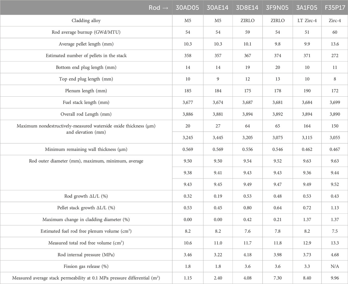
Table 1. Summarized nondestructive examination results and measured rod internal pressure, void volume, stack permeability, and fission gas release data (Montgomery et al., 2019a; Montgomery et al., 2019b; Montgomery and Morris, 2019; Montgomery and Bevard, 2023).
The neutron fluence, pellet temperature, and coolant temperature vary axially along the fuel rod during reactor operation. The fuel rod’s final condition is path dependent, and rods having the same final burnup may not have been subjected to the same local conditions in the reactor. The local variations of rod condition as a function of rod elevation are evident in the nondestructively acquired gamma count, rod outer diameter, and oxide thickness (“lift off”) previously summarized by Montgomery et al. (Montgomery et al., 2019b). The gamma counts are analogous to local fluence/burnup, and the local oxide thickness is directly related to the local cladding and coolant temperatures. The baseline rod outer diameter and oxide thickness are the product of rod temperature, fluence, power, and other parameters over operational time; therefore, it is not as directly tied to a single independent parameter.
With the exception of rods from assembly F35, the rods are typical batch fuel. The ZIRLO-clad rods are the Westinghouse North Anna Improved Fuel (NAIF/P + Z) design; the M5-clad rods are Framatome’s Advanced Mark-BW design (AMBW); the standard Zircaloy-4 (Zirc-4)-clad rod is the Westinghouse low-parasitic (LOPAR) fuel assembly design; and the low tin (LT) Zirc-4-clad rods are the Westinghouse NAIF fuel assembly design. Thus, four of the examined rods are Westinghouse-designed and manufactured and two are Framatome-designed and manufactured. The rods are thus further grouped by cladding type to look for trends. A more detailed description of the sister rods is provided by Scaglione et al. in the ORNL test plan (Scaglione et al., 2016).
Rod P17 from assembly F35 (F35P17) was a test rod, as documented by Balfour (Balfour et al., 1992). Balfour also describes the cycles of operation: “The North Anna Unit 1 reactor operated with 18-month cycles during Cores 6 and 7 following 12-month cycles for Cores 4 and 5; core design outlet temperatures at hot full power ranged from 618°F (325.6°C) in Core 4°F–624°F (328.9°C) in Core 7. These temperatures were 10°F–27°F (5.6°C–15°C) higher than in previous high-burnup programs at the Farley, Surry, and Zion reactors.” Additional detailed data on the operating conditions and the results of the poolside inspections are included by Balfour, and the measurements reported by Balfour compare well with the measurements taken by ORNL during the sister rod program for the two sister rods surveilled in the Electric Power Research Institute program (F35P17 and F35K13). Unfortunately, this level of detail is not publicly available for the other sister rods.
The reactors where the sister rods were irradiated were uprated twice. Some of the sister rod donor assemblies (F35, 30A) were operated during uprate cycles. Assembly F35 was operated early in the life of the reactor and over its lifetime had a lower average linear heat rate during operation than assembly 30A, although it was operated for four cycles. Assembly 30A was operated at the reactor’s highest rated power and linear heat rate over three cycles.
Although local segment burnup does not incorporate all parameters that influence the rod’s condition, it is publicly available and is used as an independent parameter to examine variations in the destructive examination results. The average coolant temperature—which is assumed to vary linearly from the bottom to the top of the reactor core—at the elevation of the specimen is also used as an independent correlating parameter to examine the results.
2 Heat treatments applied to selected rods
In preparation for dry storage, the volume around the fuel assemblies in the canister cavity is filled with water that must be drained and dried. Typically, the most challenging thermal condition experienced by the fuel during dry storage occurs during the drying sequence or just after drying during canister transfer to the storage pad. To better understand the effects of the drying and transfer sequence, full-length sister rods were subjected to a simulated dry-storage peak cladding temperature before destructive examinations. A comparison of the heat-treated rod data with the baseline rod data can be used to assess differences in rod properties or performance related to increased fuel rod temperature before dry storage.
A heat-treatment oven was designed and fabricated to enable full-length fuel rod heat treatment (FHT). The oven can impose a variety of normal-condition axial temperature profiles and peak cladding temperatures up to 530°C on a full-length fuel rod. In contrast with the heat treatment of rod segments in which the full-length rod is depressurized and segments are cut and repressurized, heat-treating full-length fuel rods before depressurization preserves the as-discharged internal pressure and induces the representative hoop stresses associated with bounding drying temperature conditions.
Three unpunctured fuel rods were heat-treated in the rod oven: one Zirc-4-clad (F35P17), one ZIRLO-clad (3F9N05), and one M5-clad (30AE14). To mimic the desired vacuum drying transient, the rods were heated slowly (10 °C/h), then held at 400°C (all axial elevations) for 8 h, and then slowly cooled (3.7 °C/h) to ambient temperature. A peak temperature of 400°C was selected to be applied to the full-length rods based on regulatory guidance regarding calculated peak fuel cladding temperatures for normal conditions of dry storage and short-term loading operations (US Nuclear Regulatory Commission, 2003).
The main purpose of the FHT was to investigate the effects of a phenomenon known as cladding hydride reorientation on the composite rod performance. Past testing at Argonne National Laboratory (Billone, 2019) shows that cladding hydride precipitates can be dissolved into the cladding alloy during the canister drying process, and, when the cladding cools at the slow rate expected during canister operations, the hydrides may reprecipitate in a radial orientation, depending on the cladding hydrogen inventory and the rod internal pressure. However, those tests were completed with empty cladding using aggressive rod internal pressure, whereas the FHT was performed using the whole fuel rod at its as-discharged pressure.
3 Destructive examinations completed, data collected, comparisons and trending
The sister rod examinations were specified to provide general performance characteristics, material property data, and mechanical performance properties on the baseline HBU rods and to discover any changes in performance related to vacuum drying (up to 400°C) during interim storage packaging. The pellets influence rod performance greatly in reactor operation (Cox, 1990), and the same is expected to be true in dry storage and transportation. Towards that end, the following measurements were completed on the baseline and heat-treated rods:
(1) End-of-life rod internal pressure, void volume, fission gas composition and release rate.
(2) Waterside oxide thickness and remaining cladding wall thickness, cladding hydrogen content and hydride precipitate orientation.
(3) Fatigue lifetime.
(4) Flexural modulus, elastic and plastic flexural rigidity, strain at failure in bending.
(5) Bearing capacity in transverse compression, flexural strength, and 0.2% yield strength in bending at room temperature and at 200°C.
A direct comparison of the baseline sister rods with the heat-treated sister rods was performed to identify degradation (or recovery) in mechanical performance of the rods resulting from dry storage. Each of the following subsections summarize the results of the testing completed for the destructive examinations discussed herein.
3.1 Rod internal pressure and void volume measurements
Commercial nuclear fuel rods are pre-pressurized with helium before irradiation. The magnitude of pre-pressurization varies with fuel design; at manufacture, the sister rods were pre-pressurized with helium. During irradiation, the rod internal pressure increases because fission gases (e.g., xenon, krypton) are produced and some portion of the evolved fission gases are released to the rod void volume, which increases the rod internal pressure above the as-manufactured rod pressure. The cladding stress from the rod internal pressure is typically higher in dry storage than during operation because the external pressure in dry storage is low compared to the reactor operating pressure.
The fuel rods are designed with an internal void volume that ensures the rod internal pressure is maintained within its allowable pressure, considering the fission gases that may be released from the pellet stack. The void volume changes during operation as the cladding creeps and grows, and as cracks form within the pellets. For this discussion, the void volume is defined as including the volume in the plenum of the rod that is not occupied by the spring, the gap between the pellet outer diameter and the cladding inner diameter, the volume of any pellet chamfers and dishes, and the volume of pellet cracks or open porosity at the specified temperature. Because rod internal pressure and void volume are important parameters for determining rod performance throughout its lifetime, both were measured for each of the sister rods. These results are listed in Table 1. No difference related to the heat-treatment is visible in the rod internal pressure or void volume measurements. However, Montgomery and Morris also measured the ability of gas to move through the pellet stack (Montgomery and Morris, 2019), and they concluded that the heat-treated rods had better gas transmissibility, which may be related to a permanent increase in the cladding diameter caused by the heat treatment.
3.2 Observations from imaging, dimensional measurements, and cladding hydrogen measurements
Ayanoglu et al., 2024 describes the metallographic and ceramographic imaging, observations, and conclusions reached based on the examinations. This information is important to the discussion herein because the orientation of the cladding hydrides and their influence on the cladding performance has been previously established as directly influencing the mechanical performance (Billone, 2019). Figure 1 provides representative images of the cladding condition, both for baseline and heat-treated fuel rods. The baseline cladding has circumferentially oriented hydrides, and the density and distribution of the hydrides varies depending on whether the cladding is cold-worked stress-relieved (the Zirc-4, low tin Zirc-4, and ZIRLO cladding) or fully recrystallized (the M5 cladding). In the heat-treated rods, long radial hydrides were observed in fully recrystallized (RXA) cladding. The cold-worked stress-relieved (CWSR) cladding generally had very short or no radial hydrides. This result is believed to be due to the larger inventory of hydrogen in the CWSR cladding at this burnup. Radial hydrides were located at adjacent pellet cracks. The pellet cracks seem to have influenced the location of hydride precipitates, likely by creating a favorable stress distribution in the adjacent cladding.
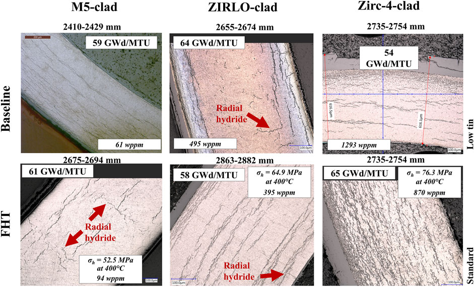
Figure 1. A comparison of the cladding hydride precipitates for baseline and FHT examples of the three cladding types.
Figure 2 shows representative images of the pellet condition for the baseline and heat-treated rods. The pellet crack morphologies were similar in the baseline and heat-treated rods within the burnup range investigated. Consistent with other studies, a mechanical and chemical pellet-clad bonded layer was observed at all investigated rod elevations, except for locations where the pellet does not contact the cladding (e.g., pellet chamfer locations). Past studies have demonstrated that fission products from the pellet are present in the cladding oxide to a depth of ∼6 µm and suggest that fission recoil during irradiation is the source of the bonding process (Lach et al., 2019). Just inside the bonded layer, a discontinuous circumferential pellet crack is observed. Both the bonded layer and the circumferential crack are deemed important for consideration in modeling the functionality of how the pellet supports the cladding. No apparent difference is visible between the pellets in the baseline and heat-treated rods.
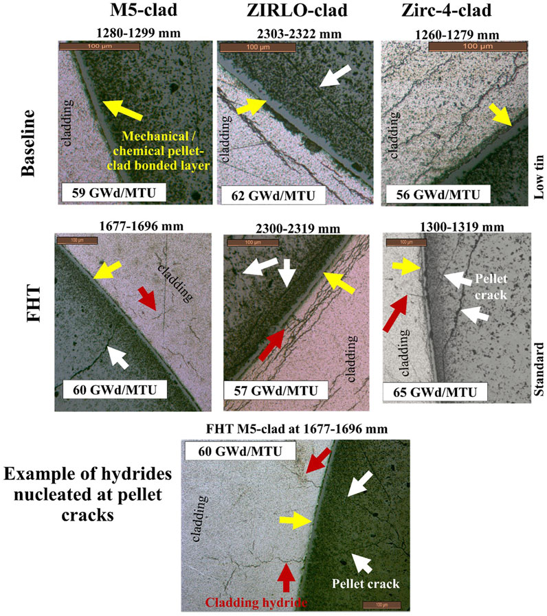
Figure 2. Optical micrographs of the pellet intact within the cladding enable the discovery of the pellet’s features’ effects on the rod performance. For example, pellet cracks (white arrows) were observed as nucleating radial cladding hydrides (red arrows), and this would not have been possible if the pellet were not included within the image. A mechanical/chemical bonded layer (yellow arrow) is developed where the pellet is in contact with the cladding.
Measurements of the cladding and pellet features derived from the metallographic imaging are summarized in Table 2 with the measured cladding hydrogen concentration for several elevations per rod. The test locations selected are from rod elevations having moderate to thick waterside oxide layers, typically near the 1,500, 2,400, and 3,200 mm rod elevations. For cladding hydrogen concentration measurements, 4 specimens around the circumference of the cladding were analyzed for each elevation and the average is reported in Table 2. The measurement process is discussed in more detail in Montgomery and Bevard, 2023.
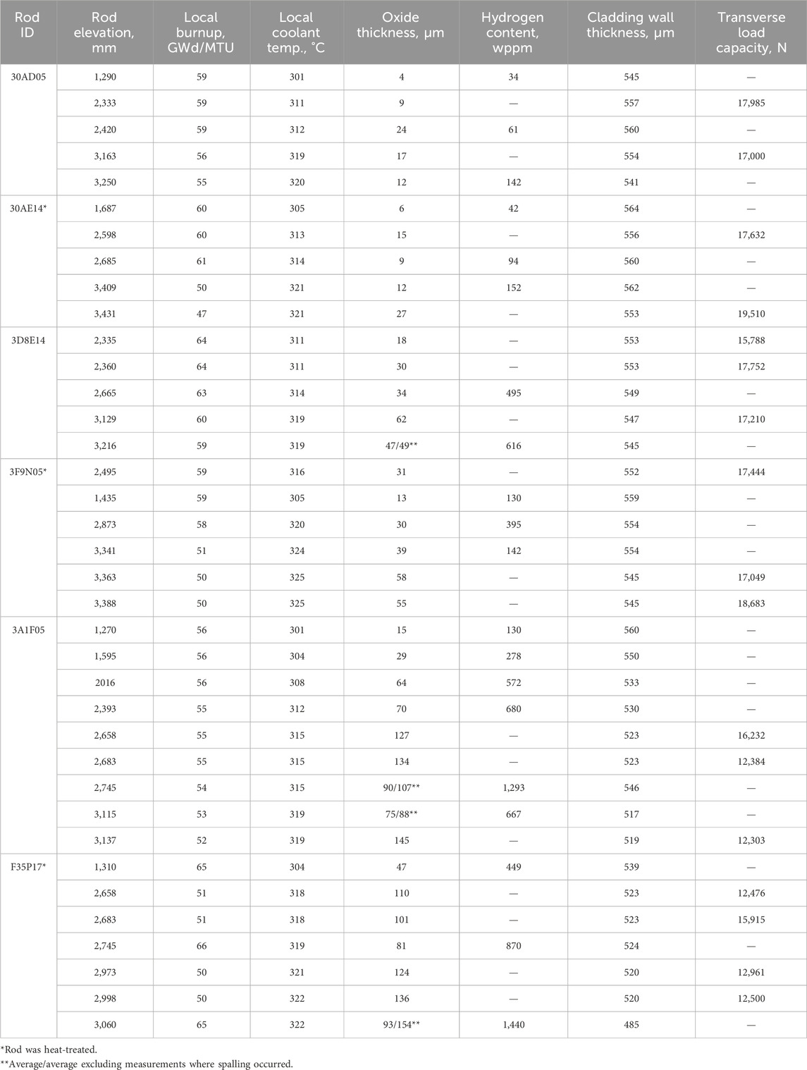
Table 2. Destructively-measured average waterside oxide thickness, average cladding hydrogen content, average cladding wall thickness, and transverse load bearing capacity.
Referring to Table 2, the overall results of the examinations indicate that the M5 cladding had the lowest waterside oxide thickness and lowest hydrogen content of the 4 alloys studied, followed by the ZIRLO cladding, the LT Zirc-4, and the Zirc-4 cladding, which had the thickest waterside oxide layer and largest hydrogen inventory. The M5 cladding hydrogen concentration data from the sister rods are very low (<200 wppm) but are slightly higher than previous data (Cole et al., 2012). The Zirc-4 cladding hydrogen concentration data are higher than the previous envelope of data (Cole et al., 2012), but F35P17 was an atypical lead test rod operated over four cycles to HBU. Previous hydrogen concentration data as a function of burnup are not currently available for comparison with the ZIRLO and LT Zirc-4 data. In general, the measured cladding hydrogen concentration for the sister rods is marginally higher than publicly available data (Garde and Slagle, 2009; Cole et al., 2012), and are therefore considered to be conservative examples for demonstration of the effects of hydrogen content on rod performance.
Montgomery and Bevard, 2023 investigated trends for the measured waterside oxide thickness, remaining cladding thickness, cladding hydrogen concentration and hydrogen pickup fractions as a function of local burnup, but they did not correlate well. An example showing cladding hydrogen concentration plotted as a function of local burnup is shown in Figure 3A. However, the cladding hydrogen concentration is very well correlated with the measured oxide thickness (see Figure 3B), which should be expected, as the hydrogen available for cladding pickup is generated through the oxidation process. Further, when plotted with estimated local coolant temperature, a trend of waterside oxide thickness (Figure 3C) and hydrogen concentration (Figure 3D) emerges that is clearly associated with specific alloys. Therefore, while there does not seem to be an alloy-specific hydrogen pickup rate, there is a distinct difference in oxidation rate and related hydrogen concentration for the different alloys.
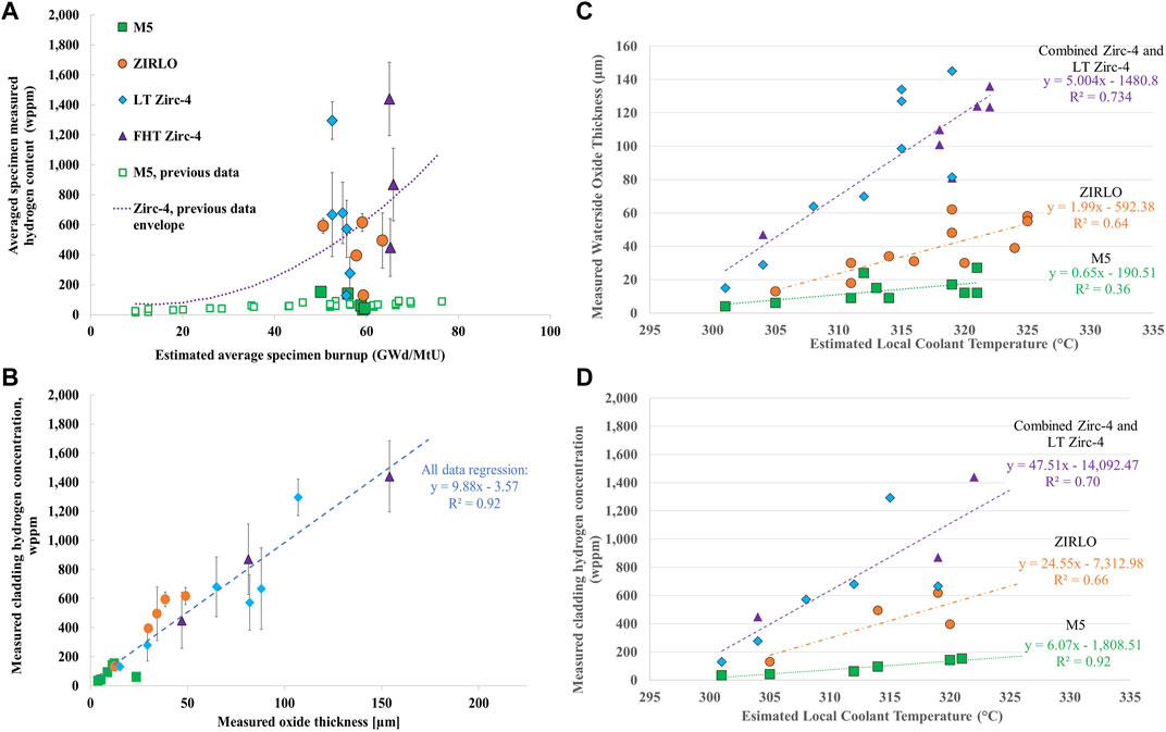
Figure 3. The measured cladding hydrogen concentration as a function of (A) average specimen local burnup and (B) measured local oxide thickness. (C) Measured cladding waterside oxide is well-correlated to estimated local coolant temperature, and (D) the measured cladding hydrogen concentration related to the waterside oxidation is also well-correlated with estimated local coolant temperature. Two of the graphs shown were originally published in Montgomery and Bevard (2023). The authors have obtained the necessary permissions to use them.
3.3 Fatigue tests
SNF assemblies must be shipped to other sites for processing and disposal. During shipment, the fuel is typically oriented horizontally, and the fuel rods are subject to periodic alternating loads related to the movement of the vehicle. These loads result in the alternating bending of the SNF rods. The number of bending cycles is related to the length of the shipping route: longer routes produce more cycles.
Fatigue performance is typically characterized by the number of cycles required to produce failure at a specified strain amplitude. Many tests are completed, and the strain amplitude is varied—even to very high amplitudes not expected during actual service—to characterize fatigue performance over a wide range of fatigue cycles. The strain amplitude data are then plotted against the measured cycles to rod fracture to obtain a characteristic fatigue curve for the tested material. Wang et al. (Wang and Wang, 2017; Wang et al., 2018) developed a method for fatigue testing the SNF segments called the Cyclic Integrated Reversible-Bending Fatigue Tester (CIRFT). A 6 in. long unpressurized fuel rod segment is placed in the CIRFT machine at room temperature and bent in a positive and negative direction (i.e., reversibly) to represent one bending fatigue cycle. The flexure cycle is imposed repeatedly until fracture occurs. The CIRFT machine is run at 5 Hz—five fatigue cycles per second. A strain amplitude is calculated by directly measuring the extent to which the rod segment bends during the test.
The data produced by Wang and Wang (2017), Wang et al. (2018) and supplemented herein through tests of the sister rods, as shown in Figure 4, indicate that the fatigue performance of the SNF segments is relatively insensitive to differences such as cladding alloy type, local oxide thickness, burnup, and reoriented cladding hydrides. The fatigue performance of the baseline fuel rod segments was similar to that of the heat-treated fuel rod segments. No obvious differences were observed between different cladding types or different fuel rod designs (9 × 9 BWR vs. 15 × 15 PWR vs. 17 × 17 PWR). Furthermore, Wang and Wang (2017), Wang et al. (2018) tested several segments that were subjected to high temperature and cladding stress to induce extreme hydride reorientation, and no difference in fatigue performance was observed.
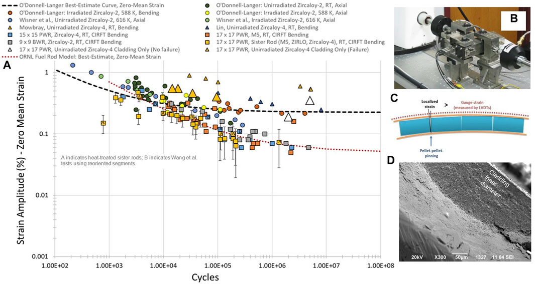
Figure 4. (A) The range of fatigue test data evaluated by ORNL for fuel rods using CIRFT (design limit shown in red) and by others for cladding tubing and coupons (design limit shown in black) highlights the differences between cladding-only and fuel rod performance. (B) The flexure mechanism used on CIRFT. (C) An illustration of the role of the pellets in creating localized strain when the rod is flexed in bending and (D) Scanning electron microscopy imaging of a specimen fractured in fatigue testing reveals that the crack nucleated at the cladding inner diameter, rather than as expected at the outer diameter. The likely explanation is that a local strain concentration is applied by pellet fragments during bending. Two of the graphs shown were originally published in Montgomery and Bevard (2023). The authors have obtained the necessary permissions to use them.
However, the tests from the sister rods indicate that fatigue performance of fuel rods is degraded when compared with tests of cladding alloys. Specifically, the best-estimate fatigue limit of the fuel rod is approximately a factor of five lower than the fatigue limit for cladding alloys (0.25% (O Donnell and Langer, 1964) vs. 0.05%). This difference is attributed to stress risers imposed on the fuel rod cladding by pellet discontinuities such as pellet–pellet gaps and pellet cracks created during reactor operation. Evidence of this phenomenon was observed in examinations of the fatigue fractures, as shown in the scanning electron microscopy image in Figure 4. Traditional solid mechanics evaluations indicate that the peak stresses on the cladding should be at the outer diameter of the cladding, and fracture should nucleate at the outer diameter of the cladding. The fractography revealed crack-like features on the inner diameter of cladding after fatigue failure, and the observed inner diameter crack initiation indicates that fatigue degradation occurs because of local strain concentration at pellet discontinuities such as pellet cracks and pellet–pellet interfaces. Therefore, a primary finding from the fatigue testing is that the pellets must be considered as an integral part of the rod structure in evaluating its performance in bending fatigue. However, as discussed by Montgomery et al. (Montgomery and Bevard, 2023), there is still significant margin to the currently available transportation loads and frequency, suggesting fatigue damage does not accumulate and fatigue failure does not occur as a result of the anticipated transportation conditions.
3.4 Bending tests
Four-point bending was selected to study the strength properties of the fuel rods at room temperature and at 200°C. The test provides values for the elastic modulus in bending and the flexural stress and flexural strain response. It is traditionally used to study brittle materials in which the number and severity of flaws exposed to the maximum stress directly relates to the flexural strength and crack initiation. Bending is the most likely loading scenario for fuel rods. When a rod is loaded in axial compression, it acts as a long, slender column and buckles, creating a bending scenario. When a lateral load is applied, the rod, pinned by the relatively fixed spacer grid supports, is subjected to bending. Therefore, understanding the rod response to bending is extremely important.
The load frame used for the bending tests, with its test fixturing, is shown in Figure 5. The frame applies a constant bending moment over the gauge length of the test specimen. The evaluation method and its uncertainties are discussed in detail by Montgomery et al. (Montgomery and Bevard, 2023); it should be noted herein that elastic beam theory is used as a practical approach to evaluate the mentioned mechanical properties. The resulting evaluated properties should not be considered cladding material properties. The sound of the rod during fracture was recorded, and the consensus is that it resembles the sound of tin cry prior to failure. A link to the video recorded during the test, which includes sound, is provided in Figure 5.
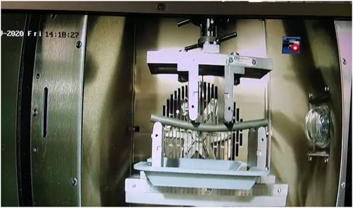
Figure 5. Four-point bend setup with a 6 in. fuel rod segment (see Supplementary Video S1).
The resulting composite fuel rod mechanical properties are listed in Table 3, and the stress vs. strain data for the room temperature and 200°C tests are plotted in Figure 6. Figure 7 plots the strain at fracture, yield strength, flexural modulus, and flexural strength as a function of the local rod burnup. Figure 8 plots the same information as a function of the average local reactor coolant temperature.
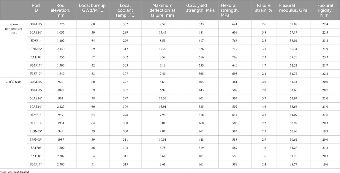
Table 3. Measured and calculated four-point bend data.
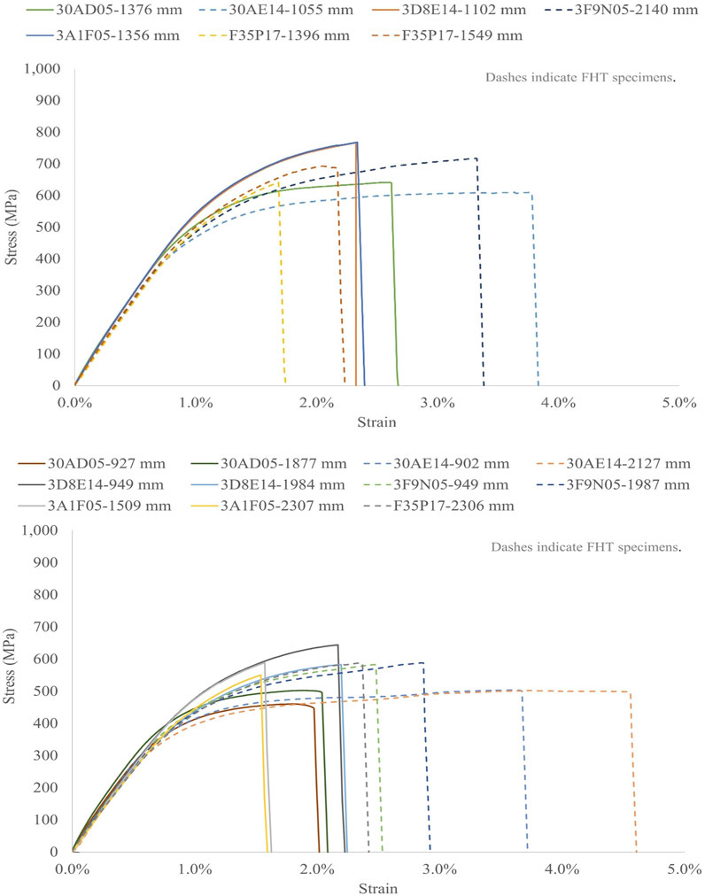
Figure 6. Measured stress versus strain for 6 in. fuel rods in four-point bending at (top) room temperature and (bottom) 200°C. The data clearly indicate a lower yield and ultimate strength and increased ductility for the FHT rods that is thought to be related to annealing of irradiation defects during the heat treatment. Two of the graphs shown were originally published in Montgomery and Bevard (2023). The authors have obtained the necessary permissions to use them.
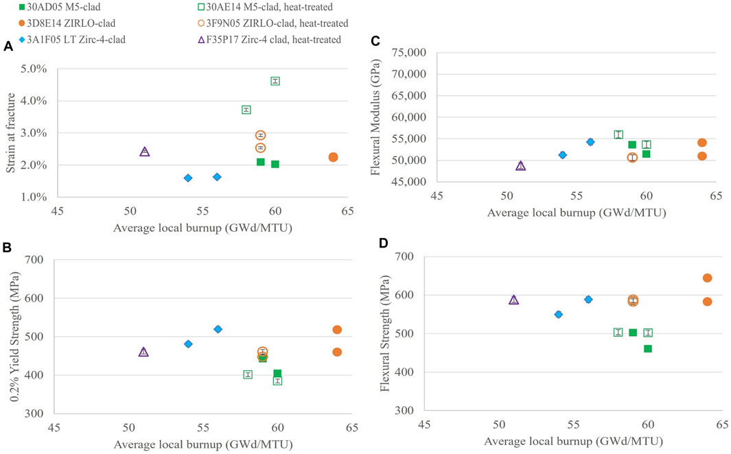
Figure 7. Calculated (A) strain at fracture, (B) 0.2% yield strength, (C) flexural modulus, and (D) flexural strength derived from the 200°C four-point bend tests plotted as a function of specimen average burnup.

Figure 8. Calculated (A) strain at fracture, (B) 0.2% yield strength, (C) flexural modulus, and (D) flexural strength derived from the 200°C four-point bend tests plotted as a function of estimated local coolant temperature at the segment elevation.
The trends investigated in Figure 7 with specimen average burnup at the specimen rod elevation did not produce a significant correlation, but the dataset is small and limited to high burnup observations. At high burnup, all of the examples have pellet-cladding interaction and pellet-cladding bonding, which could be significantly different from the performance at low burnup. Referring to Figure 7B, the M5-clad rod segments have the lowest yield and flexural strength, even though they have the thinnest waterside oxide layer and thus the most remaining cladding wall thickness. The lower strength of the M5-clad segments is attributed to its RXA microstructure and corresponding inherently ductile characteristic (Motta et al., 2015). When plotted against the estimated local coolant temperature (Figure 8), a potential correlation is observed for the CWSR cladding types (LT Zirc-4, ZIRLO, Zirc-4) for yield strength and flexural strength. The flexural modulus of all specimens (CWSR and RXA) also trends reasonably well with local coolant temperature. Montgomery et al. also investigated trends with measured local waterside oxide thickness, hydrogen concentration and reorientation, and remaining cladding thickness with limited success (Montgomery and Bevard, 2023).
Referring to Figure 6, the heat-treated rods had significantly more ductility than the baseline rods (on the order of 2 × for the M5-clad rods), which suggests that annealing of irradiation damage may have occurred during the simulated vacuum drying heat treatment. This is further indicated by the decreased yield strength and increased strain at fracture as compared with the corresponding baseline rods. Significant flexure before fracture was observed for the FHT M5 rod segments, as shown in Figure 9A for one specimen, post-fracture.
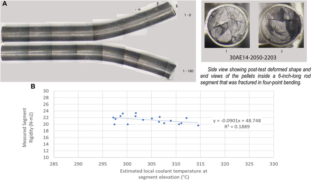
Figure 9. (A) The two-halves of a 6 in. M5-clad rod segment fractured in four-point bend clearly indicates a very large amount of deformation sustained up to fracture. This particular rod fractured in the body of a pellet, as opposed to at a pellet–pellet interface location. The vertical lines appearing in the image are an artifact of the imaging process. (B) The segment rigidity for all tests vs. the estimated coolant temperature at the segment rod elevation. Two of the graphs shown were originally published in Montgomery and Bevard (2023). The authors have obtained the necessary permissions to use them.
The measured elastic flexural modulus was comparable among all rod segments tested and did not change much for the temperatures tested (room temperature and 200°C), as expected. Although the heat treatment did not appear to affect the flexural rigidity of the rod, when all data are pooled, flexural rigidity seems to depend on the local coolant temperature during reactor operation, as shown in Figure 9B. This is likely related to annealing of irradiation defects in the cladding that occurred in reactor, as higher coolant temperature resulted in a more ductile and less rigid rod.
3.5 Ring compression tests
During the last decade, Argonne National Laboratory has developed a significant body of data on cladding hydride reorientation and the associated effects on cladding ductility using ring compression testing (RCT), as summarized by Billone, 2019. ORNL’s RCT data provide supplementary information on the transverse load-bearing capability of intact fuel rods (cladding and pellets). Similar to RCT of cladding specimens, the fueled rod segment is loaded across its diameter in compression, as shown in Figure 10. The load as a function of crosshead displacement is measured to failure. Table 2 summarizes the results of 5 tests completed at 200°C and 12 tests completed at room temperature. The specimens typically carried load until at least one cladding fracture developed.
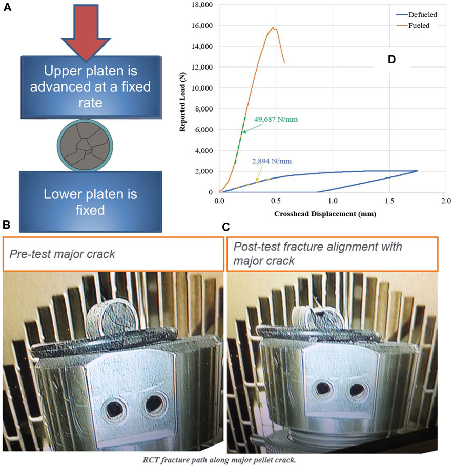
Figure 10. Transverse compression tests, (A) test configuration, (B) and (C) the pretest and posttest alignment of a preexisting pellet crack that influenced the rod segment fracture plane under the tested loading condition, and (D) the crosshead displacement vs. reported load compared for a rod segment and cladding-only test illustrates that the rod can carry ∼8 × the load in transverse compression. Two of the graphs shown were originally published in Montgomery and Bevard (2023). The authors have obtained the necessary permissions to use them.
Fueled RCT indicates a large transverse load-bearing capability, independent of hydride reorientation, at about 16.4 kN on average, with a minimum load-bearing capability of 12.3 kN for the tested segments. No appreciable difference is observed in the maximum load-bearing capability of the segments from room temperature to 200°C, and there is no apparent difference related to the heat-treatment applied to some of the rods. When the room temperature tests and the 200°C tests are plotted with the segment average burnup (Figures 11A,B) and with the average local coolant temperature at the segment’s rod elevation (Figures 11C,D), no trends are observed. However, a few points are noticeably lower in measured peak load, and suspicions were confirmed when the measured average segment waterside oxide thickness (Figure 12A) and the measured average remaining cladding wall thickness (Figure 12B) are plotted. The peak load capacity in transverse compression strongly correlates with the remaining cladding wall thickness, which is simply the thickness of the cladding wall that was not oxidized in reactor. The pelletside oxide thickness is typically thin and on the order of 10 μm, but the waterside oxidation kinetics depend on the local operating conditions and the alloy type.
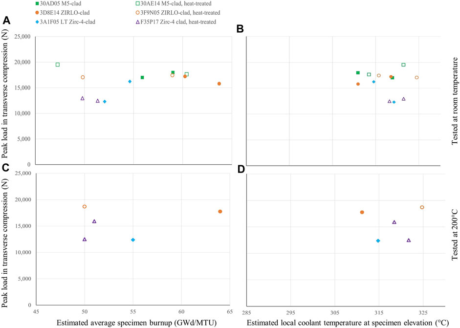
Figure 11. Measured transverse load bearing capability (room temperature and 200°C) for each specimen plotted as a function of (A), (B) the estimated average specimen burnup and (C), (D) the estimated average local coolant temperature at the specimen’s in-reactor elevation.
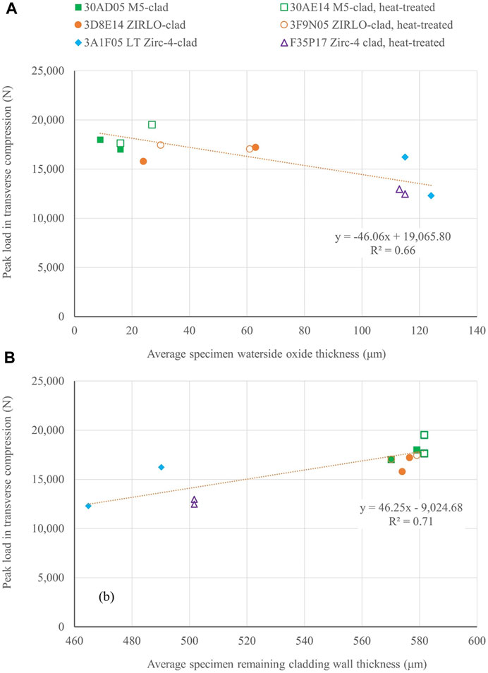
Figure 12. Peak load measured in transverse compression plotted with (A) average measured specimen waterside oxide thickness, and perhaps more appropriately, (B) the average remaining cladding wall thickness (measured nondestructively using eddy current (Montgomery et al., 2019a)).
Another primary observation is that the orientation of the major cracks in the pellet appear to nucleate fracture of the adjacent cladding and determine the pellet fracture plane, as illustrated in Figure 10. The observed failure of cladding correlated to cracks in the pellet suggests that relative pellet fragment motion may be important to predicting failure of the composite rod in transverse compression. ORNL measured failure loads of fuel rods that were significantly higher (about 8×) than defueled cladding-only tests, as shown in Figure 10.
4 Discussion and summary of key findings
The combined testing of the HBU sister rods provides a broad body of data supporting the extended interim storage and transportation performance of baseline HBU used fuel and vacuum-dried spent fuel for interim dry storage and eventual transport. In general, the HBU rods were found to be strong and durable in the expected loading conditions. For example, in bending, the rods retain significant flexural strength and ductility, even at HBU and after FHT. Fueled RCT indicates a large transverse load-bearing capability for both the baseline and FHT rods, independent of cladding alloy and any associated hydride reorientation, at about 8× the capacity of empty cladding. No appreciable difference exists in the RCT load-bearing capacity from room temperature to 200°C, and the peak load capacity correlates with the remaining cladding wall thickness, which is related to the waterside oxidation layer thickness developed during reactor operation.
Considering possible changes in performance related to dry storage vacuum drying, the measured cladding hydrogen content of the sister rods is slightly higher than, but consistent with, other available data. Strong correlations were observed between reactor local coolant temperature and waterside oxide thickness, and waterside oxide thickness and cladding hydrogen content. Hydride reorientation did occur at the imposed FHT temperatures and cladding stress (as generated by the as-discharged rod internal pressure); the M5 cladding had some long radial hydrides, and the other alloys had only very short radial hydrides. However, the radial hydride orientation did not degrade performance of the fuel rods.
Regarding the extended effects of the FHT unrelated to hydride reorientation, the heat-treatment (and thus vacuum-drying) resulted in decreased bending yield strength and increased ductility that are alloy dependent and we strongly suspect are related to the annealing of irradiation damage accumulated by the cladding during reactor operation and during vacuum drying. Fission and fill gas was shown to move more readily through the pellet stack in the heat-treated rods, and this is attributed to a permanent increase in the rod diameter that occurred because of the increased rod internal pressure during FHT.
One of the most important findings from the sister rod work is the observed influence of the pellet, pellet cracks, and pellet-to-cladding bonding on the strength and performance of the composite rod.
While the fatigue performance of HBU fuel rods appears to be unaffected by the FHT applied, hydride orientation, fuel rod type, or cladding type, the CIRFT testing found that the fatigue performance of HBU fuel rods is degraded compared with the fatigue performance of cladding alloys. This degradation appears to be caused by stress concentrations that occur at pellet–pellet interfaces or pellet cracks under bending loads. During fatigue conditions, cracks appear to initiate from the cladding inner diameter, indicating pellet interaction effects. Further, the pellets constrain deformation of the cladding under RCT conditions, resulting in significant improvement in failure loads in transverse compression, but the orientation of the major cracks in the pellet determines the pellet fracture plane, and the cracks appear to nucleate fracture of the adjacent cladding wall. Finally, the pellet cracks have been observed to nucleate hydrides at the adjacent cladding inner diameter, and the specific influence of the precipitates at these locations deserves further study.
5 Future work
One of the primary observations from this work is the effect of in-reactor and vacuum-drying local temperatures on the rod performance. These effects are likely related to the annealing of irradiation defects within the fuel rod cladding. Future work plans focus on better defining the degree of annealing of defects with time at temperature and will include bending and fatigue tests to capture resulting effects on rod performance.
Data availability statement
The original contributions presented in the study are included in the article/Supplementary material, further inquiries can be directed to the corresponding author.
Author contributions
RM: Conceptualization, Data curation, Formal Analysis, Investigation, Methodology, Project administration, Resources, Writing–original draft, Writing–review and editing. BB: Conceptualization, Funding acquisition, Methodology, Resources, Supervision, Writing–review and editing. PC: Data curation, Investigation, Methodology, Writing–review and editing. YS: Investigation, Visualization, Writing–review and editing.
Funding
The author(s) declare financial support was received for the research, authorship, and/or publication of this article. This research was sponsored by the Spent Fuel and Waste Science and Technology Program of the US Department of Energy and was carried out at Oak Ridge National Laboratory under contract DE-AC05-00OR22725 with UT-Battelle, LLC.
Acknowledgments
The authors would like to thank the staff at the Irradiated Fuels Examination Laboratory and our collaborators at Sandia National Laboratories, Pacific Northwest National Laboratory, Oak Ridge National Laboratory, Westinghouse, Framatome, Dominion Energy, and Electric Power Research Institute.
Licenses and permissions
Notice: This manuscript has been authored by UT-Battelle, LLC, under contract DE-AC05-00OR22725 with the US Department of Energy (DOE). The US government retains and the publisher, by accepting the article for publication, acknowledges that the US government retains a nonexclusive, paid-up, irrevocable, worldwide license to publish or reproduce the published form of this manuscript, or allow others to do so, for US government purposes. DOE will provide public access to these results of federally sponsored research in accordance with the DOE Public Access Plan (http://energy.gov/downloads/doe-public-access-plan).
Conflict of interest
The authors declare that the research was conducted in the absence of any commercial or financial relationships that could be construed as a potential conflict of interest.
Publisher’s note
All claims expressed in this article are solely those of the authors and do not necessarily represent those of their affiliated organizations, or those of the publisher, the editors and the reviewers. Any product that may be evaluated in this article, or claim that may be made by its manufacturer, is not guaranteed or endorsed by the publisher.
Supplementary material
The Supplementary Material for this article can be found online at: https://www.frontiersin.org/articles/10.3389/fnuen.2024.1321627/full#supplementary-material
References
Ayanoglu, M., Montgomery, R., Harp, J., and Sasikumar, Y. (2024). Metallographic examinations and hydrogen measurements of high-burnup spent nuclear fuel cladding. J. Nucl. Mater. 589 (154833), 154833. ISSN 0022-3115. doi:10.1016/j.jnucmat.2023.154833
Balfour, M. G., Kilp, G. R., Comstock, R. J., McAtee, K. R., and Thornburg, D. R. (1992). Corrosion of zircaloy-clad fuel rods in high-temperature PWRs: measurement of waterside corrosion in North Anna unit 1, TR-100408, tier 2 research Project 2757-1. Washington, D.C., United States: Electric Power Research Institute.
Billone, M. C. (2019). Ductility of high-burnup-fuel ZIRLO™ following drying and storage, ANL-19/14, M2SF-19AN010201011 Rev. 3. Lemont, IL, United States: Argonne National Laboratory.
Cole, S. E., Delafoy, D., Graebert, R. F., Louf, P.-H., and Teboul, N. (2012). “Framatome optimized fuel rods for LWRs,” in Proceedings of the Water Reactor Fuel Performance Meeting/Top Fuel, Manchester, UK, September, 2012, 230.
Cox, B. (1990). Pellet-clad interaction (PCI) failures of zirconium alloy fuel cladding — a review. J. Nucl. Mater. 172 (3), 249–292. doi:10.1016/0022-3115(90)90282-r
Garde, A. M., and Slagle, W. H. (2009). Hydrogen pick up fraction for ZIRLOTM cladding corrosion and resulting impact on the cladding integrity. Proc. Water React. Fuel Perform. Meet. – WRFPM/Top Fuel, 268.
Lach, T. G., Edwards, D. J., Buck, E. C., McNamara, B. K., Schwantes, J. M., and Clark, R. A. (2019). Fission recoil-induced microstructural evolution of the fuel-cladding interface [FCI] in high burnup BWR fuel. J. Nucl. Mater. 521, 120–125. doi:10.1016/j.jnucmat.2019.04.044
Montgomery, R., and Bevard, B. B. (2023). Sister rod destructive examinations (FY22). ORNL/SPR-2023/2935. https://www.osti.gov/biblio/1986208.
Montgomery, R., and Morris, R. N. (2019). Measurement and modeling of the gas permeability of high burnup pressurized water reactor fuel rods. J. Nucl. Mater. 523, 206–215. ISSN 0022-3115. doi:10.1016/j.jnucmat.2019.05.041
Montgomery, R., Morris, R. N., Bruce, B., and Scaglione, J. (2019b). Key results from detailed nondestructive examinations of 25 pressurized water reactor high burnup spent nuclear fuel rods. Nucl. Sci. Eng. 193 (8), 884–902. doi:10.1080/00295639.2019.1573602
Montgomery, R., Bevard, B., Morris, R. N., Goddard Jr, J., Smith, S. K., and Hu, J. (2019a). Sister rod nondestructive examination final report, SFWD-SFWST-2017-000003 Rev. 1 (M2SF-17OR010201021)/ORNL/SPR-2017/484 Rev. 1 (ORNL/SPR-2018/801). Oak Ridge, TN, United States: Oak Ridge National Laboratory.
Motta, A. T., Couet, A., and Comstock, R. J. (2015). Corrosion of zirconium alloys used for nuclear fuel cladding. Annu. Rev. Mater. Res. 45 (1), 311–343. doi:10.1146/annurev-matsci-070214-020951
O Donnell, W. J., and Langer, B. F. (1964). Fatigue design basis for Zircaloy components. Nucl. Sci. Eng. 20 (1), 1–12. doi:10.13182/nse64-a19269
Scaglione, J. M., Montgomery, R. A., and Bevard, B. B. (2016). Post-irradiation examination plan for high burnup demonstration Project sister rods. SFWD-SFWST-2017-000090 ORNL/SR-2016/708. Oak Ridge, TN, United States: Oak Ridge National Laboratory.
US Nuclear Regulatory Commission (2003). Spent fuel Project office, interim staff guidance 11 revision 3, cladding considerations for the transportation and storage of spent fuel, SFST-ISG-11 Revision. Rockville, Maryland, United States: US Nuclear Regulatory Commission.
Wang, J.-A., and Wang, H. (2017). Mechanical fatigue testing of high burnup fuel for transportation applications. NUREG/CR-7198/R1.
Keywords: sister rods, sibling pins, spent fuel interim storage, spent fuel transportation, fuel rod mechanical strength, fuel rod fatigue, fuel rod bending test, hydride reorientation
Citation: Montgomery R, Bevard B, Cantonwine P and Sasikumar Y (2024) Key results from examinations of seven high burnup pressurized water reactor spent nuclear fuel rods. Front. Nucl. Eng. 3:1321627. doi: 10.3389/fnuen.2024.1321627
Received: 14 October 2023; Accepted: 19 February 2024;
Published: 21 March 2024.
Edited by:
Tonya Vitova, Karlsruhe Institute of Technology (KIT), GermanyReviewed by:
Sarah C. Finkeldei, University of California, Irvine, United StatesEdgar C. Buck, Pacific Northwest National Laboratory (DOE), United States
Copyright © 2024 Montgomery, Bevard, Cantonwine and Sasikumar. This is an open-access article distributed under the terms of the Creative Commons Attribution License (CC BY). The use, distribution or reproduction in other forums is permitted, provided the original author(s) and the copyright owner(s) are credited and that the original publication in this journal is cited, in accordance with accepted academic practice. No use, distribution or reproduction is permitted which does not comply with these terms.
*Correspondence: Rose Montgomery, montgomeryra@ornl.gov