Research on active and passive schemes for safety improvement of nuclear energy hydrogen production system
 Qunxiang Gao
  Qi Sun
 Wei Peng
- Key Laboratory of Advanced Reactor Engineering and Safety of Ministry of Education, Institute of Nuclear and New Energy Technology, Cooperation Innovation Center of Advanced Nuclear Energy Technology, Tsinghua University, Beijing, China
Nuclear hydrogen production has the advantages of large-scale and low carbon emissions, and is expected to play an active role in the energy transition process. However, the storage and transportation of hydrogen pose potential risks of leakage and diffusion when connected to high-pressure hydrogen storage tanks and pipelines. To address this concern, this study focused on designing three distinct safety improvement schemes tailored for potential hydrogen leakage accidents. These schemes encompassed a passively distributed arrangement of obstacles (Scheme 1), a passively centralized arrangement of obstacles (Scheme 2), and an active fan array blowing (Scheme 3). Numerical simulation methods were applied on extensive spatial scales for relevant calculations. The results revealed that all three schemes effectively reduced the diffusion distance of combustible hydrogen. Specifically, at lower ambient wind speeds, Scheme 1, Scheme 2, and Scheme 3 achieved the shortest diffusion distances of 123 m, 56 m, and 46 m, respectively. Meanwhile, at higher ambient wind speeds, the corresponding distances were 282 m, 100 m, and 79 m. These results collectively offer valuable insights to mitigate the risk of leakage accidents in nuclear hydrogen production systems.
1 Introduction
In recent years, the widespread adoption of hydrogen energy worldwide has precipitated the global energy transformation and advanced the implementation of various low-carbon policies (Drela, 2021; Hassan et al., 2024). This clean energy source boasts diverse origins, a high calorific value, and non-polluting combustion products (Chavda et al., 2022), making it a promising candidate to replace fossil fuels in the 21st century. Utilizing the heat generated by fourth-generation modular high-temperature gas-cooled reactors (Wu et al., 2021) to produce hydrogen can meet large-scale demand and emit almost no greenhouse gases, thus having good commercialization prospects (Gao et al., 2021; Gao et al., 2023). The nuclear energy hydrogen production system consists of two main components: a nuclear power plant and a hydrogen production chemical plant. To design and construct the system, the distance between these two elements must be carefully considered. Simulating the leakage accident scenario of the high-pressure hydrogen storage tank in the chemical plant is crucial to ensure that the downstream nuclear power plant remains unaffected by combustible hydrogen. While increasing the distance between nuclear power plants and chemical plants enhances safety, it introduces additional challenges, such as heat loss in the high-temperature helium delivery pipeline. Therefore, exploring various means to mitigate the impact of a leakage accident on the nuclear power plant is essential to enhance overall system safety.
The typical high-pressure gaseous hydrogen storage method often results in a high-pressure underexpanded jet during leakage, where momentum governs the long-range dispersion. Continuous entrainment of external air leads to a gradual reduction in the core concentration of the hydrogen jet until complete dispersion in the atmospheric environment occurs. Over the years, scholars have conducted experimental studies to investigate hydrogen leakage processes. In this respect, Lach et al. (Lach et al., 2020; Lach and Gaathaug, 2021) examined large-scale hydrogen release and ignition in confined spaces, measuring peak pressure. Zou et al. (Zou et al., 2023) established a visualization platform for hydrogen leakage and developed a calibrated schlieren technology that can accurately reflect the relationship between hydrogen concentration and schlieren image grayscale. Sommersel et al. (Sommersel et al., 2009) conducted concentration measurements and captured flame propagation during hydrogen release in pipelines. Besides, Gong et al. (Gong et al., 2022) measured hydrogen concentration released at various temperatures in storage tanks and derived relational expressions for diffusion distance. Shen et al. (Shen et al., 2023) conducted a simulation analysis on the leakage problem of hydrogen fuel cell vehicles, studied the impact of wind direction on hydrogen leakage in the chassis, and measured the hydrogen leakage rate under different working conditions. Wang et al. (Wang et al., 2020) studied the development of jet fires and explosions resulting from spontaneous combustion of high-pressure hydrogen, recording shock wave overpressure and flame optical signals. Based on the background of soil corrosion and hydrogen embrittlement, Zhang et al. (Zhang and Zhao, 2023) established a leakage model of underground hydrogen pipelines and studied the effects of leakage holes, soil type, pipeline pressure, and pipeline diameter on hydrogen leakage and diffusion. Kobayashi et al. (Kobayashi et al., 2018) performed a 90 MPa high-pressure hydrogen release experiment, analyzing the influence of different nozzle diameters on leakage flow rate.
Numerical simulation research on hydrogen leakage has also made continuous progress in recent years. Xie et al. (Xie et al., 2024) explored the law of hydrogen leakage and diffusion in ship engine rooms, simulated the influence of multiple factors such as ventilation volume, leakage diameter and temperature on leakage diffusion, and put forward suggestions for sensor installation. Lee et al. (Lee et al., 2022) utilized FLACS software for a simulation study on hydrogen leakage in private residential areas, discussing the impact of ventilation system configuration on diffusion. Wang et al. (Wang et al., 2023) analyzed the transient and steady-state diffusion behavior of hydrogen leakage and diffusion in actual hydrogen production containers, used the equivalent TNT method to evaluate the possible harm caused by extreme accidents, and guided the relevant settings of the ventilation structure. Qian et al. (Qian et al., 2020a) and Li et al. (Qian et al., 2020b) simulated hydrogen refueling station leakage accidents, considering wind speed, wind direction, and leakage location, analyzing airflow vortices near the tank. Su et al. (Su et al., 2022) studied the leakage and diffusion characteristics of hydrogen mixed with natural gas in household kitchens, analyzed the influence of mixing ratio, leakage rate, ventilation conditions and other factors, and provided references for explosion hazard areas, alarm response times, concentration distribution and other indicators. Li et al. (Li et al., 2018; Li et al., 2021; Mao et al., 2021) modeled hydrogen fuel cell ships, studying the most dangerous areas during leakage accidents and devising possible escape plans. Yuan et al. (Yuan et al., 2022) conducted a numerical simulation study on a leakage and explosion in China’s first liquid hydrogen refueling station, revealed the exacerbating effect of the current trailer parking location on the risk consequences, and analyzed the effects of the leakage equivalent diameter and wind speed. Bauwens et al. (Bauwens and Dorofeev, 2014) employed OpenFOAM software for numerical analysis of hydrogen diffusion in large warehouses, determining combustible hydrogen distribution areas.
In contrast to other hydrogen leakage scenarios, nuclear hydrogen production involves relatively large hydrogen reserves. In the event of a complete high-pressure hydrogen storage tank leak, the combustible part’s diffusion range can extend hundreds of meters, challenging the operational safety of nuclear power plants. While past studies have considered obstacle arrangements to hinder hydrogen diffusion, they often featured simplistic structures and shapes, focusing on small spatial scales. This study utilizes numerical simulation to model the nuclear energy hydrogen production system’s high-pressure hydrogen storage tank on a large spatial scale. It proposes a cost-effective obstacle layout and fan array purging plan to mitigate hydrogen leakage risks. Additionally, the study estimates hydrogen diffusion and deflagration distances under different schemes, providing insights for enhancing the safety design of future nuclear energy hydrogen production systems.
2 Models
2.1 Geometric model
Two studies were conducted on leakage and dispersion in nuclear hydrogen production systems. The first aimed to identify the worst-case leakage accident conditions of the nuclear hydrogen production system designed by the Institute of Nuclear and New Energy Technology at Tsinghua University (Gao et al., 2022a). The second study compared the effectiveness of obstacles with different shapes in preventing hydrogen diffusion (Gao et al., 2022b). The active scheme involved establishing a fan array downstream of the chemical plant to create a reverse airflow, purging the hydrogen jet and preventing its diffusion. The passive scheme focused on constructing obstacles along the hydrogen jet to alter its trajectory or dilute the concentration. Notably, two classifications of passive schemes were considered: decentralized and centralized arrangements. The decentralized approach entailed dividing the open space between the nuclear power plant and the chemical plant into ecological forest areas, serving as a natural barrier for large-scale leakage accidents while also maintaining a green environment. Alternatively, cylindrical mounds were manually piled downstream of the jet to create small obstacles, offering cost-effective diffusion prevention. The concentrated arrangement involved constructing a large obstacle with superior performance downstream of the jet, incurring a certain construction cost.
Figure 1 illustrates the security improvement scheme in this study, featuring a high-pressure hydrogen storage tank with a diameter of 2.5 m, a height of 8 m, and a calculation area of 600 m × 600 m × 200 m. Scheme 1 adopted a passive distributed arrangement, with each conical mound having a bottom surface diameter and height of 2 m. The distance between the centers of cone bases was 4 m, and the first row of soil mounds was positioned 10 m away from the hydrogen storage tank. Scheme 2 employed a passive centralized arrangement, utilizing semi-cylindrical obstacles with a curved surface diameter and width of 20 m, positioned 30 m away from the hydrogen storage tank. Scheme 3 utilized an active fan array with a height and width of 10 m, positioned 30 m away from the hydrogen storage tank.
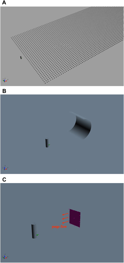
Figure 1. Design of safety improvement scheme for nuclear hydrogen production system. (A) Scheme 1: Passive decentralized arrangement. (B) Scheme 2: Passive centralized arrangement. (C) Scheme 3: Active fan array purge.
2.2 Governing equation
The process of leakage and diffusion involves the exchange of mass, momentum, and energy between hydrogen and air, with the entrainment of hydrogen by air also involving component transfers. The related equations are as follows:
The continuity equation is:
The momentum equation is:
The energy equation is:
The species transport equation is:
where Ui is the velocity (m/s), ρ is the density (kg/m3), P is the pressure (Pa), μ is the molecular viscosity (kg/(m·s)), h is the fluid enthalpy (m2/s2), λ is the thermal conductivity (W/(m·K)), T is the temperature (K), Yi is the local mass fraction of species i, Ji is the species diffusion flux.
In addition, the kinetic energy of the hydrogen jet changes drastically in the initial stage of leakage and diffusion, and the Shear Stress Transport (SST) k-ω turbulence model, known for its superior calculation accuracy and applicability (Yu and Thé, 2016; Adegboye et al., 2021), is employed for more accurate representation (Menter, 1994):
where k is the turbulence kinetic energy (m2/s2), ω is the specific dissipation rate (s-1), σ is the turbulent Prandtl number, μt is the eddy viscosity (kg/(m·s)), Ω is the vorticity magnitude (s-1), and the remaining variables are the empirical parameters of the model.
This study uses the SIMPLEC algorithm to solve the velocity field and pressure field. Since the distance between the leak port and the Mach Disk is very small, the hydrogen gas quickly expands to atmospheric pressure at the Mach Disk location after leaving the leak port. Therefore, this study uses the conditions of the Mach Disk position instead of the conditions of the leakage port to simplify the complex calculation of the expansion area and thereby improve the convergence. In terms of calculation assumptions, this study uses a full buoyancy model, ignores interphase interactions, and performs calculations based on the ideal gas assumption and constant pressure specific heat. In addition, this study assumes that the upstream pressure is a constant value and the air flow direction does not change with changes in air pressure.
2.3 Boundary conditions and model validation
Figure 2 illustrates the mesh division of the model, while Table 1 outlines the diverse boundary conditions employed in the study. Meshing utilizes a structured grid. Our study assessed the changes in jet centerline concentration across different grid numbers—166,000, 254,000, 398,000, and 546,000. Notably, at 254,000 grids, the concentration changes stabilized, satisfying the prerequisites for subsequent calculations.
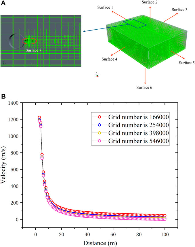
Figure 2. Meshing of the model. (A) Schematic diagram of meshing. (B) Grid independence verification.
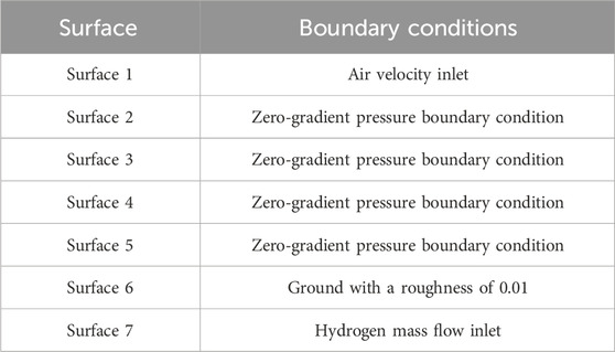
Table 1. Boundary conditions.
Hu et al. (Hu et al., 2018) conducted experimental measurements involving the concentration field of a helium jet impinging on an obstacle. The experimental setup included an initial pressure of 15 MPa and a 0.5 mm nozzle. The axial distance between the obstacle and the nozzle was varied at 0.2 m, 0.3 m, and 0.4 m. A thermal conductivity sensor mounted on the obstacle’s surface measured the concentration on the vertical centerline. Figure 3 illustrates the comparison between the simulation method employed in this study and the experimental results. The comparison revealed that the concentration change trend on the vertical centerline under different working conditions was consistent between the simulation and experimental results. Furthermore, the maximum absolute error was within 2%. This alignment indicated the suitability of the current model for calculating high-pressure hydrogen leakage scenarios.
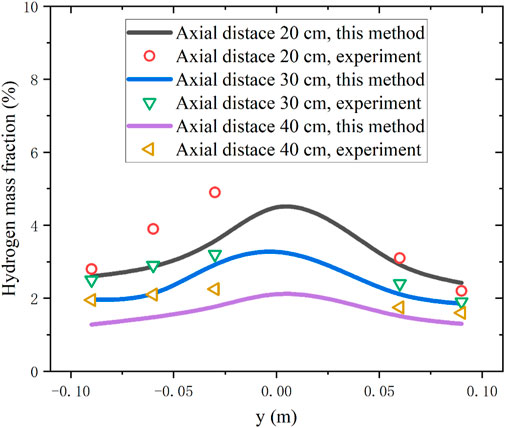
Figure 3. Model validation for calculation of high-pressure hydrogen leakage.
3 Results and discussion
This section focuses on calculating the leakage accident conditions of the nuclear hydrogen production system designed by the Institute of Nuclear and New Energy Technology at Tsinghua University. We sought to compare the diffusion distance and explosion distance of various security improvement schemes. The specific accident calculation conditions are outlined in Table 2. For this study, it is assumed that hydrogen clouds with a volume fraction exceeding 4% are flammable. The calculations consider two distinct working conditions with varying wind speeds.
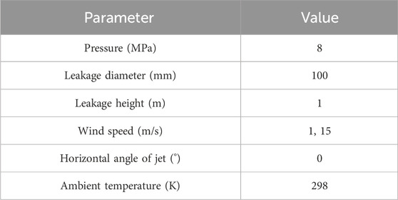
Table 2. Input parameters for leakage accidents.
3.1 The effect of the passive decentralized layout scheme
In the examination of this security improvement scheme, we classified the placement of hydrogen storage tanks and conical mounds, conducting calculations for four distinct cases as depicted in Figure 4. The variations between these cases were twofold. Firstly, it involved the orientation of the hydrogen storage tank leak, either facing a specific mound in the first row or directed towards the gap between the mounds in the first row. Secondly, it considered whether the mounds were arranged in a linear alignment or a staggered arrangement.
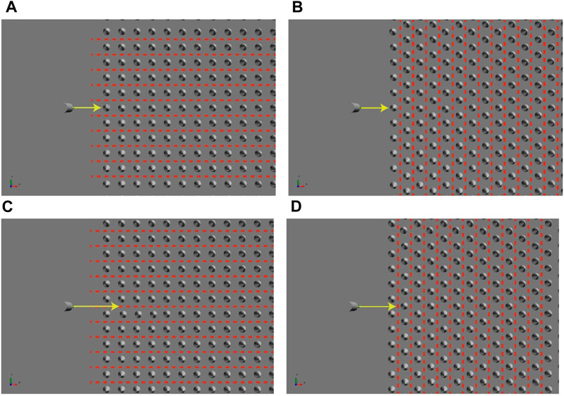
Figure 4. The case for passive decentralized arrangement. (A) Case 1: the hydrogen storage tank is facing the soil mound, aligned arrangement. (B) Case 2: the hydrogen storage tank is facing the soil mound, staggered arrangement. (C) Case 3: the hydrogen storage tank is facing the gap, aligned arrangement. (D) Case 4: the hydrogen storage tank is facing the gap, staggered arrangement.
Figure 5 shows the calculated results for the four cases under different wind speeds. Table 3 provides a summary of the diffusion distances of combustible hydrogen in these cases. Notably, the kinetic energy of the hydrogen jet yielded a prolonged impact at higher wind speeds, resulting in a more extensive spread. Observations revealed that, at wind speeds of 1 m/s and 15 m/s, the shortest diffusion distance of hydrogen occurred when soil mounds were arranged in a staggered manner. This outcome could be attributed to the soil mound effectively dividing the hydrogen jet into multiple streams upon impact, and the staggered arrangement continues this division, continuously diluting the overall concentration. Conversely, when the hydrogen jet was directed towards the gap and the mounds were arranged in an aligned manner, the diffusion distance is the longest. In this scenario, the gap did not shield the diffusion of the jet, and the kinetic energy decreased more gradually, leading to a more extensive spread.
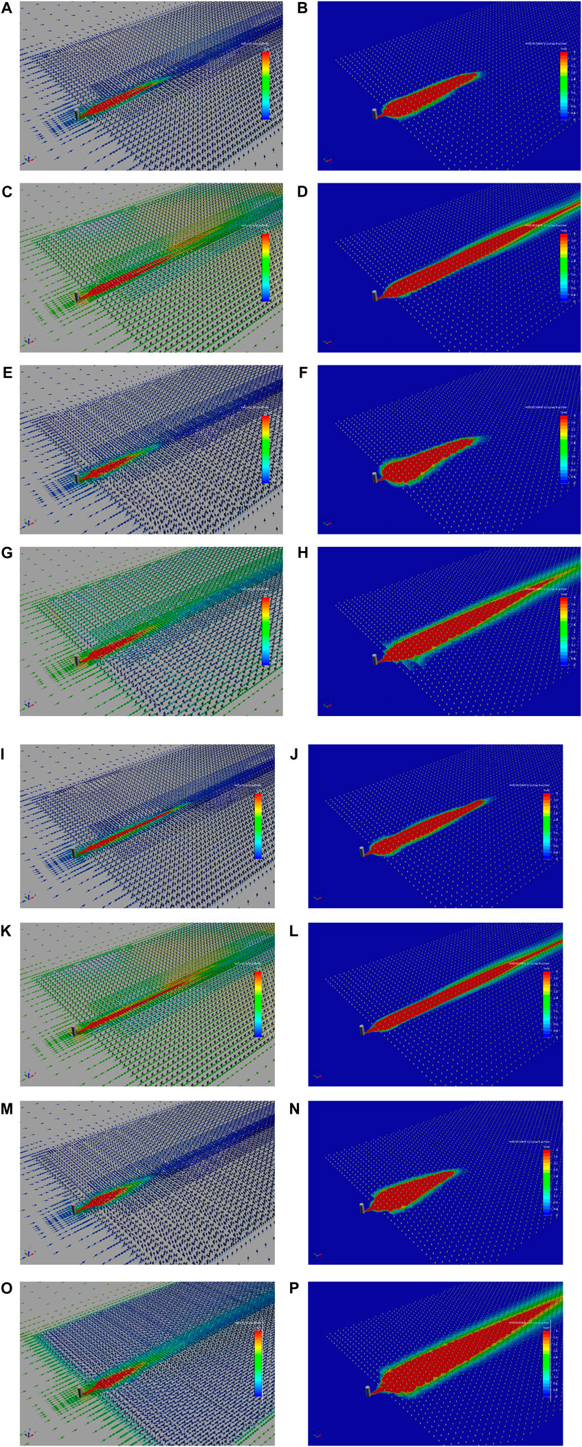
Figure 5. Flow field and concentration field of passive distributed arrangement scheme. (A) Case 1, 1 m/s wind speed: flow field (B) Case 1, 1 m/s wind speed: concentration field (C) Case 1, 15 m/s wind speed: flow field (D) Case 1, 15 m/s wind speed: concentration field (E) Case 2, 1 m/s wind speed: flow field (F) Case 2, 1 m/s wind speed: concentration field (G) Case 2, 15 m/s wind speed: flow field (H) Case 2, 15 m/s wind speed: concentration field (I) Case 3, 1 m/s wind speed: flow field (J) Case 3, 1 m/s wind speed: concentration field (K) Case 3, 15 m/s wind speed: flow field (L) Case 3, 15 m/s wind speed: concentration field (M) Case 4, 1 m/s wind speed: flow field (N) Case 4, 1 m/s wind speed: concentration field (O) Case 4, 15 m/s wind speed: flow field (P) Case 4, 15 m/s wind speed: concentration field
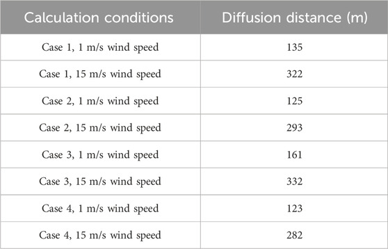
Table 3. Diffusion distance statistics of passive distributed arrangement scheme.
3.2 The effect of passive centralized layout scheme
Figure 6 shows the calculation results of the passive centralized arrangement scheme. Notably, the kinetic energy of the hydrogen jet experienced a rapid attenuation upon encountering the obstacle, a phenomenon that substantially diminished the diffusion distance. In this respect, under low wind speeds, the buoyancy effect of hydrogen became significant in proximity to the obstacle, causing the majority of combustible hydrogen to manifest above the obstacle. Conversely, under high wind speeds, the kinetic energy of the hydrogen jet underwent continuous replenishment from the swiftly moving air currents in the environment, thereby resulting in an augmented diffusion distance. It is worth noting that our investigation involved the utilization of half-cylindrical surfaces with a consistent structure. However, a notable distinction from previous studies lies in the straight edge of the semi-cylindrical surface upon ground contact, deviating from the previously employed arc-shaped configuration. This alteration introduced a distinct dynamic. For instances where the wind speed was 1 m/s and 15 m/s, the diffusion distances of combustible hydrogen gas were 56 m and 100 m, respectively.
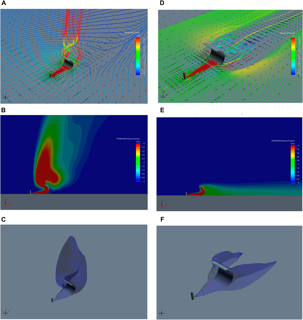
Figure 6. Flow field, concentration field, and isosurface of passive centralized arrangement scheme. (A) Flow field with a wind speed of 1 m/s. (B) Concentration field with a wind speed of 1 m/s. (C) Isosurface of 4% volume concentration with a wind speed of 1 m/s. (D) Flow field with a wind speed of 15 m/s. (E) Concentration field with a wind speed of 15 m/s. (F) Isosurface of 4% volume concentration with a wind speed of 15 m/s.
3.3 The effect of active fan array blowing
Within this section, the influence of the active fan array blowing, specifically the fan array purge, was examined. The fan’s wind speed varied at 5 m/s, 10 m/s, and 15 m/s. Illustrated in Figure 7 are the distinct flow fields and isosurfaces corresponding to these different operational states. The semi-transparent blue region delineates the boundary of the hydrogen cloud, characterized by a volume concentration of 4%. Table 4 provides a summary of the diffusion distances of combustible hydrogen across diverse operational conditions. When the ambient wind speed was 1 m/s, the fan’s wind speed surpassed the ambient wind speed, instigating a pronounced reverse airflow that could impede hydrogen diffusion while concurrently expanding the range of diffusion. With escalating fan speeds, the entrainment of hydrogen by the air intensified, leading to a continuous contraction of the isosurface depicting combustible hydrogen. In instances where the ambient wind speed reached 15 m/s, even though the fan’s speed did not exceed the ambient wind speed, the impact of ambient wind remained significant, thereby prolonging the diffusion distance. However, the accelerated fan speed contributed to concentration dilution, presenting a scenario where, in comparison to lower fan speeds, the diffusion distance could be diminished.
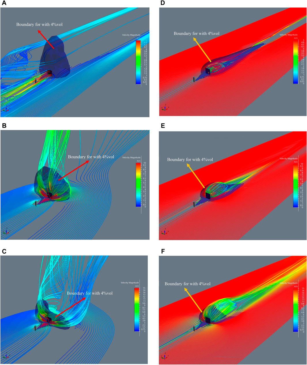
Figure 7. Flow field and isosurface with volume concentration of 4% of active fan array purging solution. (A) The wind speed of the fan is 5 m/s, and the ambient wind speed is 1 m/s (B) The wind speed of the fan is 10 m/s, and the ambient wind speed is 1 m/s (C) The wind speed of the fan is 15 m/s, and the ambient wind speed is 1 m/s (D) The wind speed of the fan is 5 m/s, and the ambient wind speed is 15 m/s (E) The wind speed of the fan is 10 m/s, and the ambient wind speed is 15 m/s (F) The wind speed of the fan is 15 m/s, and the ambient wind speed is 15 m/s.
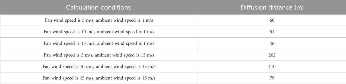
Table 4. Diffusion distance statistics of active fan array purging solution.
4 Conclusion
This investigation centers on the backdrop of a leakage accident within the nuclear hydrogen production system, comparing the efficacy of three distinct safety enhancement schemes through numerical simulations. Specifically, the schemes evaluated are the passive dispersed layout (involving numerous conical mounds), the passive centralized layout (involving a single semi-cylindrical surface), and the active fan array blowing scheme. Under a wind speed of 1 m/s, the respective shortest diffusion distances for the passive dispersed layout, passive centralized layout, and active fan array blowing scheme are 123 m, 56 m, and 46 m. As the wind speed elevates to 15 m/s, the corresponding diffusion distances expand to 282 m, 100 m, and 79 m for the aforementioned schemes. Notably, implementing mitigation measures unequivocally reduces the diffusion distance of combustible hydrogen, thereby enhancing safety. The passive solution’s distinct advantage lies in its independence from constant monitoring, accompanied by its low construction and maintenance costs. On the other hand, the proactive solution offers flexibility in adjusting response measures based on the evolving accident scenario, facilitating swift responses. Future security solutions can be tailored to specific application scenarios and engineering practices, allowing for a nuanced selection of safety measures.
The mitigation measures for leakage accidents in nuclear hydrogen production systems proposed in this study are an idealized solution. The impact of topography and surface roughness has not been considered, and optimization analysis of different solutions has not yet been carried out. Future research should fully integrate actual project scenarios and needs, comprehensively consider environmental policies, regulatory factors and other potential risks, and propose safety improvement plans that are more suitable for real nuclear energy hydrogen production systems.
Data availability statement
The original contributions presented in the study are included in the article/Supplementary material, further inquiries can be directed to the corresponding author.
Author contributions
QG: Methodology, Writing–original draft. QS: Software, Writing–review and editing. PZ: Validation, Writing–review and editing. GZ: Writing–review and editing. WP: Supervision, Writing–review and editing, Funding acquisition.
Funding
The author(s) declare financial support was received for the research, authorship, and/or publication of this article. This project was supported by the National Key R&D Program of China (Grant No. 2020YFB1901600), the National Natural Science Foundation of China (Grant No. 72374122) and the National S&T Major Project (Grant No. ZX069).
Conflict of interest
The authors declare that the research was conducted in the absence of any commercial or financial relationships that could be construed as a potential conflict of interest.
The author(s) declared that they were an editorial board member of Frontiers, at the time of submission. This had no impact on the peer review process and the final decision.
Publisher’s note
All claims expressed in this article are solely those of the authors and do not necessarily represent those of their affiliated organizations, or those of the publisher, the editors and the reviewers. Any product that may be evaluated in this article, or claim that may be made by its manufacturer, is not guaranteed or endorsed by the publisher.
References
Adegboye, M. A., Karnik, A., and Fung, W.-K. (2021). Numerical study of pipeline leak detection for gas-liquid stratified flow. J. Nat. Gas Sci. Eng. 94, 104054. doi:10.1016/j.jngse.2021.104054
Bauwens, C. R., and Dorofeev, S. B. (2014). CFD modeling and consequence analysis of an accidental hydrogen release in a large scale facility. Int. J. Hydrogen Energy 39, 20447–20454. doi:10.1016/j.ijhydene.2014.04.142
Chavda, A., Mehta, P., and Harichandan, A. (2022). Numerical analysis of multiphase flow in chemical looping reforming process for hydrogen production and CO2 capture. Exp. Comput. Multiph. Flow 4, 360–376. doi:10.1007/s42757-021-0105-7
Drela, K. (2021). Harnessing solar energy and green hydrogen–the energy transition. Procedia Comput. Sci. 192, 4942–4951. doi:10.1016/j.procs.2021.09.272
Gao, Q., Qu, X., Peng, W., Zhang, P., and Chen, S. (2022b). Influence of obstacle morphology on safety of nuclear hydrogen production system. Int. J. Hydrogen Energy 47, 36733–36748. doi:10.1016/j.ijhydene.2022.08.235
Gao, Q., Sun, Q., Zhang, P., Peng, W., and Chen, S. (2021). Sulfuric acid decomposition in the iodine–Sulfur cycle using heat from a very high temperature gas-cooled reactor. Int. J. Hydrogen Energy 46, 28969–28979. doi:10.1016/j.ijhydene.2020.08.074
Gao, Q., Wang, L., Peng, W., Zhang, P., and Chen, S. (2022a). Safety analysis of leakage in a nuclear hydrogen production system. Int. J. Hydrogen Energy 47, 4916–4931. doi:10.1016/j.ijhydene.2021.11.099
Gao, Q., Zhang, P., Sun, Q., Zhang, P., Chen, S., and Peng, W. (2023). Experimental and numerical investigation of sulfuric acid decomposition for hydrogen production via iodine–sulfur cycle. Energy Convers. Manag. 289, 117167. doi:10.1016/j.enconman.2023.117167
Gong, L., Yang, S., Han, Y., Jin, K., Lu, L., Gao, Y., et al. (2022). Experimental investigation on the dispersion characteristics and concentration distribution of unignited low-temperature hydrogen release. Process Saf. Environ. Prot. 160, 676–682. doi:10.1016/j.psep.2022.02.055
Hassan, Q., Algburi, S., Jaszczur, M., Al-Jiboory, A. K., Al Musawi, T. J., Ali, B. M., et al. (2024). Hydrogen role in energy transition: a comparative review. Process Saf. Environ. Prot. 184, 1069–1093. doi:10.1016/j.psep.2024.02.030
Hu, J., Christopher, D. M., and Li, X. (2018). Simplified partitioning model to simulate high pressure under-expanded jet flows impinging vertical obstacles. Int. J. Hydrogen Energy 43, 13649–13658. doi:10.1016/j.ijhydene.2018.05.036
Kobayashi, H., Naruo, Y., Maru, Y., Takesaki, Y., and Miyanabe, K. (2018). Experiment of cryo-compressed (90-MPa) hydrogen leakage diffusion. Int. J. Hydrogen Energy 43, 17928–17937. doi:10.1016/j.ijhydene.2018.07.145
Lach, A. W., and Gaathaug, A. V. (2021). Large scale experiments and model validation of Pressure Peaking Phenomena-ignited hydrogen releases. Int. J. Hydrogen Energy 46, 8317–8328. doi:10.1016/j.ijhydene.2020.12.015
Lach, A. W., Gaathaug, A. V., and Vaagsaether, K. (2020). Pressure peaking phenomena: unignited hydrogen releases in confined spaces–Large-scale experiments. Int. J. Hydrogen Energy 45, 32702–32712. doi:10.1016/j.ijhydene.2020.08.221
Lee, J., Cho, S., Cho, H., Cho, S., Lee, I., Moon, I., et al. (2022). CFD modeling on natural and forced ventilation during hydrogen leaks in a pressure regulator process of a residential area. Process Saf. Environ. Prot. 161, 436–446. doi:10.1016/j.psep.2022.03.065
Li, F., Yuan, Y., Yan, X., Malekian, R., and Li, Z. (2018). A study on a numerical simulation of the leakage and diffusion of hydrogen in a fuel cell ship. Renew. Sustain. Energy Rev. 97, 177–185. doi:10.1016/j.rser.2018.08.034
Li, X.-j., Xu, Y.-x., Li, X., Jin, Z.-j., and Qian, J.-y. (2021). Effect of wind condition on unintended hydrogen release in a hydrogen refueling station. Int. J. Hydrogen Energy 46, 5537–5547. doi:10.1016/j.ijhydene.2020.11.036
Mao, X., Ying, R., Yuan, Y., Li, F., and Shen, B. (2021). Simulation and analysis of hydrogen leakage and explosion behaviors in various compartments on a hydrogen fuel cell ship. Int. J. Hydrogen Energy 46, 6857–6872. doi:10.1016/j.ijhydene.2020.11.158
Menter, F. R. (1994). Two-equation eddy-viscosity turbulence models for engineering applications. AIAA J. 32, 1598–1605. doi:10.2514/3.12149
Qian, J.-y., Li, X.-j., Gao, Z.-x., and Jin, Z.-j. (2020a). A numerical study of unintended hydrogen release in a hydrogen refueling station. Int. J. Hydrogen Energy 45, 20142–20152. doi:10.1016/j.ijhydene.2020.05.063
Qian, J.-y., Li, X.-j., Gao, Z.-x., and Jin, Z.-j. (2020b). A numerical study of hydrogen leakage and diffusion in a hydrogen refueling station. Int. J. Hydrogen Energy 45, 14428–14439. doi:10.1016/j.ijhydene.2020.03.140
Shen, Y., Lv, H., Zheng, T., Liu, Y., Zhou, W., and Zhang, C. (2023). Temporal and spatial evolution of hydrogen leakage and diffusion from tube fittings on fuel cell vehicles under the effect of ambient wind. Renew. Sustain. Energy Rev. 185, 113596. doi:10.1016/j.rser.2023.113596
Sommersel, O. K., Bjerketvedt, D., Vaagsaether, K., and Fannelop, T. (2009). Experiments with release and ignition of hydrogen gas in a 3 m long channel. Int. J. Hydrogen Energy 34, 5869–5874. doi:10.1016/j.ijhydene.2009.02.058
Su, Y., Li, J., Yu, B., and Zhao, Y. (2022). Numerical investigation on the leakage and diffusion characteristics of hydrogen-blended natural gas in a domestic kitchen. Renew. Energy 189, 899–916. doi:10.1016/j.renene.2022.03.038
Wang, T., Huang, T., Hu, S., Li, Y., Yang, F., and Ouyang, M. (2023). Simulation and risk assessment of hydrogen leakage in hydrogen production container. Int. J. Hydrogen Energy 48, 20096–20111. doi:10.1016/j.ijhydene.2023.02.038
Wang, Z., Zhang, H., Pan, X., Jiang, Y., Wang, Q., Xiao, J., et al. (2020). Experimental and numerical study on the high-pressure hydrogen jet and explosion induced by sudden released into the air through tubes. Int. J. Hydrogen Energy 45, 5086–5097. doi:10.1016/j.ijhydene.2019.12.072
Wu, H., Gui, N., Yang, X., Tu, J., and Jiang, S. (2021). Parameter analysis and wall effect of radiative heat transfer for CFD-DEM simulation in nuclear packed pebble bed. Exp. Comput. Multiph. Flow 3, 250–257. doi:10.1007/s42757-020-0058-2
Xie, Y., Liu, J., Qin, J., Xu, Z., Zhu, J., Liu, G., et al. (2024). Numerical simulation of hydrogen leakage and diffusion in a ship engine room. Int. J. Hydrogen Energy 55, 42–54. doi:10.1016/j.ijhydene.2023.10.139
Yu, H., and Thé, J. (2016). Validation and optimization of SST k-ω turbulence model for pollutant dispersion within a building array. Atmos. Environ. 145, 225–238. doi:10.1016/j.atmosenv.2016.09.043
Yuan, W., Li, J., Zhang, R., Li, X., Xie, J., and Chen, J. (2022). Numerical investigation of the leakage and explosion scenarios in China's first liquid hydrogen refueling station. Int. J. Hydrogen Energy 47, 18786–18798. doi:10.1016/j.ijhydene.2022.04.060
Zhang, W., and Zhao, G. (2023). Leakage and diffusion characteristics of underground hydrogen pipeline. Petroleum. doi:10.1016/j.petlm.2023.06.002
Keywords: nuclear hydrogen production, hydrogen leakage and diffusion, active and passive solutions, diffusion distance, high temperature gas-cooled reactor (HTGR)
Citation: Gao Q, Sun Q, Zhang P, Zhao G and Peng W (2024) Research on active and passive schemes for safety improvement of nuclear energy hydrogen production system. Front. Nucl. Eng. 3:1381737. doi: 10.3389/fnuen.2024.1381737
Received: 04 February 2024; Accepted: 20 March 2024;
Published: 11 April 2024.
Edited by:
Francesco Di Maio, Politecnico di Milano, ItalyReviewed by:
Yandong Hou, Northeast Electric Power University, ChinaLuteng Zhang, Chongqing University, China
Copyright © 2024 Gao, Sun, Zhang, Zhao and Peng. This is an open-access article distributed under the terms of the Creative Commons Attribution License (CC BY). The use, distribution or reproduction in other forums is permitted, provided the original author(s) and the copyright owner(s) are credited and that the original publication in this journal is cited, in accordance with accepted academic practice. No use, distribution or reproduction is permitted which does not comply with these terms.
*Correspondence: Wei Peng, pengwei@tsinghua.edu.cn