Efficient nonresonant dipole force on molecules by a tightly focused laser
 Xing Nan Sun1
  Bum Suk Zhao
 Doo Soo Chung
- 1Molecule Optics and Bioanalytical Chemistry Lab, Department of Chemistry, Seoul National University, Seoul, South Korea
- 2Department of Chemistry, School of Natural Science, Ulsan National Institute of Science and Technology, Ulsan, South Korea
- 3Department of Physics, School of Natural Science, Ulsan National Institute of Science and Technology, Ulsan, South Korea
When a molecule is placed in a nonresonant laser field, the Stark interactions between the laser field and the induced molecular dipole result in a mechanical force on the molecule. This nonresonant dipole force is proportional to the intensity gradient of the laser, thus requiring a strong and focused pulsed laser for a sizable impact on the molecule. 36.4 mJ pulses of a 1064 nm Nd:YAG laser focused with a 17.5 cm focal length convex lens produced a 6.4 m/s change in the transverse velocity of a CS2 molecular beam. Using spherical mirrors with shorter focal lengths such as 10.0, 7.5, and 5.0 cm, dipole forces of similar magnitude were obtained with laser pulses of much lower energies. In particular the 5.0 cm focal length spherical mirror provided an 11.3 m/s change in the transverse velocity using 3.6 mJ laser pulses. This corresponds to 18-fold increase in the deflection efficiency, the ratio between the maximum velocity change and the pulse energy. From the improved efficiency, the nonresonant dipole force can be exerted with ease.
Introduction
Molecule optics that controls the molecular external degrees of freedom using optical forces from light-matter interactions has grown into a major branch of physics [1, 2]. Most widely used optical force is the dipole force—mechanical force of light resulting from molecular induced dipole-light field interactions. Due to the small magnitudes of induced dipoles, focused beams of high energy nonresonant infrared (IR) pulsed lasers have been used to exert a nonresonant dipole force to a molecule. Some examples include a molecule lens focusing a molecular beam [3–5], a molecule prism spatially separating a molecular mixture beam [6], a moving periodic optical potential slowing down or accelerating molecules [7–9], and correlated rotational alignment spectroscopy with aligning molecules non-adiabatically [10]. Ideas such as deflection of pre-aligned molecules were also proposed [11, 12].
One practical difficulty in molecule optics is the use of a high energy laser which causes issues with molecular ionization and optical component damages. We solved these problems by tight focusing of a laser exerting dipole forces. The dipole force on a molecule is proportional to the gradient of the optical field intensity. In comparison, the direct ionization probability by n photons is proportional to the n-th power of the intensity. Thus, if a lower energy laser is focused more tightly to obtain a dipole force of a similar magnitude, the molecular ionization is significantly reduced, in addition to the laser handling ease. When an IR laser is used for a nonresonant dipole force, more photons are needed than in the case of a visible laser to ionize a molecule. Therefore, the advantage of tight focusing will be more pronounced. Using focusing units of different focal lengths, pulses from a 1064 nm Nd:YAG laser were focused on a CS2 molecular beam to compare the nonresonant dipole force efficiency. By focusing with a 5.0 cm focal length spherical mirror, 3.6 mJ pulses produced an 11.3 m/s change in the transverse velocity of the molecular beam. Meanwhile a velocity change of 6.4 m/s was obtained by focusing 36.4 mJ pluses with a 17.5 cm focal length convex lens. The deflection efficiency, given as the ratio of the maximum velocity change and the pulse energy, was improved 18 times greater with a tighter focusing of the IR laser.
Materials and Methods
The experimental setup was similar to the one used by Zhao et al. [4]. CS2 vapor at room temperature was mixed with Ar to 2 atm and expanded to a vacuum system through a pulsed valve at 10 Hz (9-365-900 Solenoid Valve, Parker Instrumentation, Fairfield, NJ, USA). The vacuum system consisted of source and detection chambers, separated by a skimmer (Beam Dynamics, Minneapolis, MN, USA) with a 0.51 mm diameter hole. The source chamber was pumped by a 2400 L/s diffusion pump (VHS-6, Varian, San Francisco, CA, USA) and a rotary backing pump, yielding a 1.1 × 10⁻⁶ Torr pressure. Figure 1 shows the detection chamber that had a 20 cm cube with a 2.25 inch window for a laser beam to enter the chamber. There was also a 40 cm time of flight (TOF) tube with a 2D-imaging detector at its end. The 2D-imaging detector was a chevron-type microchannel plate (MCP, 3040-FM, Galileo, Sturbridge, MA, USA) and a P47 phosphor screen. The pressure inside the detection chamber was approximately 6 × 10⁻⁷ Torr, maintained by pumping with a 250 L/s turbo molecular pump (Turbo-V 250, Varian) and a rotary backing pump.
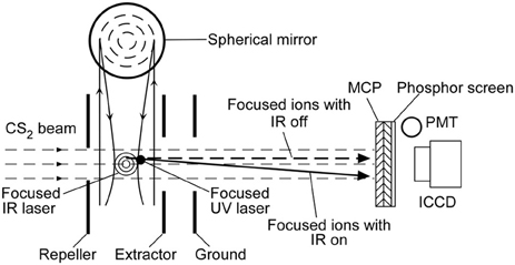
Figure 1. Schematic of the experimental layout. The molecular beam propagates along the z-axis while the laser beam is along the x-axis. The molecular beam is deflected by an IR laser pulse along the y-axis and then ionized by a UV laser pulse.
The expanded gas was collimated by the skimmer to create a molecular beam going through a 0.6 mm pinhole. The molecular beam was then deflected by a focused IR (wavelength λ = 1064 nm) pulse (10 ns) of a linearly polarized Nd:YAG laser (Powerlite 8000, Continuum, Santa Clara, CA, USA). A Glan-laser polarizer and a half wave plate controlled the polarization direction and IR laser intensity. After a 30 ns delay, the deflected molecular beam was crossed by a focused ultraviolet (UV, λ = 355 nm) pulse (10 ns) of another Nd:YAG laser (Surelite II-10, Continuum). The temporal profiles of both IR and UV laser beams were recorded by a photodiode. The UV laser ionized molecules through multiphoton-ionization processes [13]. The focusing degrees were changed by using different focusing components. A 17.5 cm focal length convex lens was placed in front of the detection chamber window to focus the IR and UV lasers. For tighter focusing, spherical mirrors of 5.0, 7.5, and 10.0 cm focal lengths were placed inside the chamber using a triple axis feed-through (PSM-1502, MDC, Hayward, California, USA). We controlled the input laser energy before focusing by a half wave plate and a linear polarizer. The IR laser focus center, laser propagation direction, and molecular beam axis were chosen as the origin, x-axis, and z-axis, respectively.
There was an electrostatic lens system of three electrode plates: a repeller, extractor and ground in the detection chamber. The electrostatic lens system details were provided in our previous report [14]. When the ions were focused onto the MCP by using a combination of three electrodes without grids, ions of the same velocity were mapped onto the same position regardless of their initial positions. This focusing electrode configuration performed velocity map imaging (VMI) [15] detecting the changes in molecular velocities deflected by the nonresonant dipole force by the IR laser pulse. The focal length of the electrostatic lens was controlled by the ratio of the extractor voltage and repeller voltage. The VMI condition in this report was 900, 600, and 0 V for the repeller, extractor, and ground, respectively. The accelerated ions arrived at the 2D detector 13.9 μs after ionization. When the focused molecular ions hit the MCP, the ion signals were amplified and electrons were emitted from its back. The emerged electrons impinged on the phosphor screen, which led to the phosphor screen flash. An intensified CCD camera (ICCD, DH534-18F-04, Andor, Belfast, UK) recorded the images on the phosphor screen. A photomultiplier tube (PMT; 1P21/E717-21, Hamamatsu, Hamamatsu City, Japan) and an oscilloscope (LT344, LeCroy, Seoul, Korea) were also used to measure the TOF of the focused molecular ions.
We scanned the UV laser focus in the y-axis by tilting the reflection mirror by 0.5 μm or 1 μm division. In our experimental setup, tilting the reflection mirror 1 μm resulted in 0.76, 1.13, 1.53, and 2.31 μm movement of the UV laser focus for the 5.0, 7.5, 10.0, and 17.5 cm focusing units, respectively. 1500 shot images were averaged, 60 pixels along the x-axis near the x-center were binned, and the profile was fit to a Gaussian function to obtain the y-center at each of the UV laser's y-position.
Results and Discussion
The velocity shift of the molecules of mass m in the y-direction by the dipole force is then given by Stapelfeldt et al. [3], Zhao et al. [4], and Chung et al. [14]
where ΔY is the distance between the y-centers of ion images obtained with the IR laser turned on and off. TOF is time of flight of the deflected ions. The y value is the y-coordinate of the UV laser focus with respect to that of the IR laser at the origin. α is the molecular polarizability and η the impedance of vacuum. I0, ω0, and τ are the peak intensity, beam waist radius, and pulse duration (full width at half maximum), respectively.
To investigate the effects of the nonresonant dipole force by the IR laser pulse on the molecular beam, the experimentally obtained Δvy values (= ΔY/TOF) were compared with the theoretical predictions provided in Equation (1). The beam waist radius (ω0) was determined by fitting the results to Equation (1). Figure 2A shows that 36.4 mJ/pulse IR laser pulses focused with the 17.5 cm focal length convex lens produced Δvmax = 6.7 m/s at y = ± ω0/2 with ω0 = 15.7 μm. When the spherical mirror of 10.0 cm focal length inside the detection chamber was used, 9.1 mJ IR pulses produced Δvmax = 6.6 m/s and ω0 = 9.5 μm (Figure 2B). Thus the tightly focused laser pulses of one-quarter energy exerted nonresonant dipole forces of similar magnitudes on CS2 molecules. Furthermore, with the 7.5 cm focal length spherical mirror, laser pulses with only one-tenth energy of 3.6 mJ/pulse produced Δvmax = 6.3 m/s and ω0 = 8.1 μm (Figure 2C). When the 5.0 cm focal length spherical mirror was used for 3.6 mJ/pulse IR laser pulses, a tighter focusing yielded Δvmax = 11.6 m/s and ω0 = 4.0 μm (Figure 2D). The average ω0 and Δvmax values are listed in Table 1. At 10 mJ/pulse or lower energy levels, the complications from molecular ionization and optical component damages were practically non-existing.
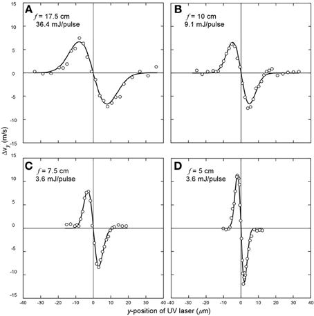
Figure 2. Deflection curves of the transverse velocity change along the y-axis vs. the relative y-position. (A) Focusing the IR laser with a 17.5 cm focal length lens for 36.4 mJ/pulse, I0 = 0.65 × 10¹² W/cm2. (B) Focusing the IR laser with a 10.0 cm focal length mirror for 9.1 mJ/pulse. I0 = 0.47 × 10¹² W/cm2. (C) Focusing the IR laser with a 7.5 cm focal length mirror for 3.6 mJ/pulse. I0 = 0.43 × 10¹² W/cm2. (D) Focusing the IR laser with a 5.0 cm focal length lens for 3.6 mJ/pulse. I0 = 1.09 × 10¹² W/cm2. The circles are the measured velocity changes along the y-axis and the solid lines are fits to Equation (1).
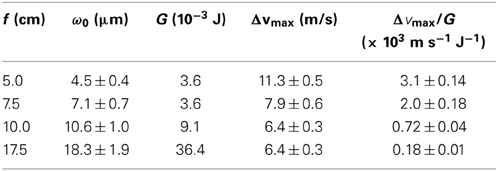
Table 1. Molecular deflection with tight focusing.
In a Gaussian-beam optical system, the beam waist radius is given by Saleh and Teich [16]
where f is the focal length of the focusing mirror (or lens) and ωL is the radius of the collimated beam at the mirror (or lens). The 1/e2 width of the IR laser beam equal to 2ωLwas 9.6 mm. M2 is the quality factor (1.0 for an ideal Gaussian beam). Figure 3 is a plot of ω0 vs. f. The circles are the data from the deflection curves using Equation (1) and the solid line represents Equation (2) with M2 = 1. Our data shows that the focused spot size was proportional to the focal length of the focusing unit with M2 = 1.5 as shown with a dotted line.
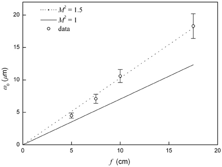
Figure 3. The relationship between the beam waist radius and focal length. The measured data are denoted by the circles. The solid line is a plot of Equation (2) with M2 = 1 and the dotted line with M2 = 1.5.
Using the energy per pulse of a Gaussian profile, G, the deflection efficiency of the dipole force defined as Δvmax/G becomes
Figure 4 shows a plot of the deflection efficiency as a function of ω0. When the focal length of the focusing unit was reduced, the deflection efficiency increased to 0.18 × 10³ (f = 17.5 cm), 0.72 × 10³ (f = 10.0 cm), 2.0 × 10³ (f = 7.5 cm), and 3.1 × 10³ (f = 5.0 cm) m s−1 J−1. Therefore, the deflection efficiency was enhanced more than 18-fold with tighter focusing using the 5.0 cm spherical mirror compared to the 17.5 cm convex lens. The results are listed in Table 1. The solid line represents the theoretical deflection efficiency of Equation (3) using α = 9.7 × 10−40 C m2 V−1, η = 376.7 Ω, vz = 498 m/s [17], m = 1.26 × 10⁻²⁵ kg, and τ = 10 ns. The experimental data provided with error bars showed a similar pattern with the theoretical line, but more deviation from the theoretical line with smaller ω0. The deflection efficiency of the dipole force in Stapelfeldt et al. [3] was about 1.2 × 10³ m s−1 J−1. For comparison, the result in Stapelfeldt et al. [3] with the corresponding theoretical line using their experimental parameters is shown in Figure 4.
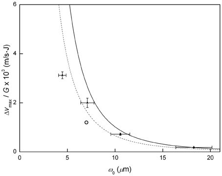
Figure 4. Deflection efficiency (Δvmax/G) vs. ω0. The solid line represents the deflection efficiency in Equation (3). The filled triangles are the experimental data. The dashed line represents the deflection efficiency with the experimental conditions in Stapelfeldt et al. [3], and the circle is the result from Stapelfeldt et al. [3].
Conclusions
Using a short focal length mirror, we demonstrated that a low energy laser pulse could exert a nonresonant dipole force on the molecule to yield a sizable impact on the molecular motion. The gradient of the focused laser intensity was increased to result in a larger dipole force with a shorter focal length. 1/10 energy IR laser pulses focused by a 5.0 cm mirror produced a 1.8-fold change in the transverse velocity of a CS2 molecular beam compared to the case with a 17.5 cm lens. The deflection efficiency was enhanced 18-fold. Therefore, the nonresonant dipole can be utilized for molecule optics with much less concern for problems such as ionization, fragmentation of molecules, or optical component damages. A high energy pulsed laser at a fixed wavelength hitherto was used for molecular deflection. If a tightly focused laser of 5 mJ pulse energy, readily available from a tunable laser over the visible and near IR ranges, is used for molecular deflection, more interesting investigations on molecule optics can be carried out.
Conflict of Interest Statement
The authors declare that the research was conducted in the absence of any commercial or financial relationships that could be construed as a potential conflict of interest.
Acknowledgments
This work was supported by the Interdisciplinary Research Program from the Research Institute for Basic Sciences, Seoul National University and by the National Research Foundation of Korea (2011-0015360 and NRF-2012R1A1A1041789). Bum Suk Zhao acknowledges support from TJ Park Science Fellowship.
References
1. Seideman, T. New means of spatially manipulating molecules with light. J Chem Phys. (1999) 111:4397–405. doi: 10.1063/1.479204
2. Lemeshko, M, Krems, RV, Doyle, JM, and Kais, S. Manipulation of molecules with electromagnetic fields. Mol Phys. (2013) 111:1648–82. doi: 10.1080/00268976.2013.813595
3. Stapelfeldt, H, Sakai, H, Constant, E, and Corkum, P. Deflection of neutral molecules using the nonresonant dipole force. Phys Rev Lett. (1997) 79:2787. doi: 10.1103/PhysRevLett.79.2787
4. Zhao, BS, Chung, HS, Cho, K, Lee, S, Hwang, SH, Yu, J, et al. Molecular lens of the nonresonant dipole force. Phys Rev Lett. (2000) 85:2705–8. doi: 10.1103/PhysRevLett.85.2705
5. Purcell, SM, and Barker, PF. Tailoring the optical dipole force for molecules by field-induced alignment. Phys Rev Lett. (2009) 103:153001. doi: 10.1103/PhysRevLett.103.153001
6. Zhao, BS, Lee, SH, Chung, HS, Hwang, S, Kang, WK, Friedrich, B, et al. Separation of a benzene and nitric oxide mixture by a molecule prism. J Chem Phys. (2003) 119:8905. doi: 10.1063/1.1613934
7. Fulton, R, Bishop, A, Shneider, M, and Barker, P. Controlling the motion of cold molecules with deep periodic optical potentials. Nat Phys. (2006) 2:465–8. doi: 10.1038/nphys339
8. Bishop, A, Wang, L, and Barker, P. Creating cold stationary molecular gases by optical Stark deceleration. New J Phys. (2010) 12:073028. doi: 10.1088/1367-2630/12/7/073028
9. Maher-McWilliams, C, Douglas, P, and Barker, P. Laser-driven acceleration of neutral particles. Nat Photon. (2012) 6:386–90. doi: 10.1038/nphoton.2012.87
10. Schröter, C, Kosma, K, and Schultz, T. CRASY: mass-or electron-correlated rotational alignment spectroscopy. Science (2011) 333:1011–5. doi: 10.1126/science.1204352
11. Gershnabel, E, and Averbukh, IS. Deflection of field-free aligned molecules. Phys Rev Lett. (2010) 104:153001. doi: 10.1103/PhysRevLett.104.153001
12. Gershnabel, E, and Averbukh, IS. Controlling molecular scattering by laser-induced field-free alignment. Phys Rev A. (2010) 82:033401. doi: 10.1103/PhysRevA.82.033401
13. Couris, S, Patsilinakou, E, Lotz, M, Grant, ER, Fotakis, C, Cossart−Magos, C, et al. The (2+ 1) multiphoton ionization spectrum of jet−cooled CS between 54 000 58 000 cm. J Chem Phys. (1994) 100:3514. doi: 10.1063/1.466393
14. Chung, HS, Zhao, BS, Lee, SH, Hwang, S, Cho, K, Shim, S-H, et al. Molecular lens applied to benzene and carbon disulfide molecular beams. J Chem Phys. (2001) 114:8293. doi: 10.1063/1.1367380
15. Brouard, M, Campbell, EK, Johnsen, AJ, Vallance, C, Yuen, WH, and Nomerotski, A. Velocity map imaging in time of flight mass spectrometry. Rev Sci Instrum. (2008) 79:123115. doi: 10.1063/1.3036978
Keywords: nonresonant dipole force, carbon disulfide, focusing, deflection, molecule optics
Citation: Sun XN, Shin SE, Zhao BS and Chung DS (2014) Efficient nonresonant dipole force on molecules by a tightly focused laser. Front. Physics 2:34. doi: 10.3389/fphy.2014.00034
Received: 13 February 2014; Accepted: 11 May 2014;
Published online: 02 June 2014.
Edited by:
Robert Moszynski, University of Warsaw, PolandReviewed by:
Raúl A. Rica, ICFO - The Institute of Photonic Sciences, SpainRosario Gonzalez-Ferez, Universidad de Granada, Spain
Copyright © 2014 Sun, Shin, Zhao and Chung. This is an open-access article distributed under the terms of the Creative Commons Attribution License (CC BY). The use, distribution or reproduction in other forums is permitted, provided the original author(s) or licensor are credited and that the original publication in this journal is cited, in accordance with accepted academic practice. No use, distribution or reproduction is permitted which does not comply with these terms.
*Correspondence: Doo Soo Chung, Molecule Optics and Bioanalytical Chemistry Lab, Department of Chemistry, Seoul National University, Seoul 151-747, South Korea e-mail: dschung@snu.ac.kr;
Bum Suk Zhao, Department of Chemistry, School of Natural Science, Ulsan National Institute of Science and Technology, 50 UNIST-gil, Bldg. 103, Ulsan 689-798, South Korea e-mail: zhao@unist.ac.kr