The Ultrastructure of Bone and Its Relevance to Mechanical Properties
 Henry P. Schwarcz
 Diab Abueidda2
  Iwona Jasiuk
- 1School of Geography and Earth Sciences, McMaster University, Hamilton, ON, Canada
- 2Department of Mechanical Science and Engineering, University of Illinois at Urbana-Champaign, Urbana, IL, United States
Bone is a biologically generated composite material comprised of two major structural components: crystals of apatite and collagen fibrils. Computational analysis of the mechanical properties of bone must make assumptions about the geometric and topological relationships between these components. Recent transmission electron microscope (TEM) studies of samples of bone prepared using ion milling methods have revealed important previously unrecognized features in the ultrastructure of bone. These studies show that most of the mineral in bone lies outside the fibrils and is organized into elongated plates 5 nanometers (nm) thick, ~80 nm wide and hundreds of nm long. These so-called mineral lamellae (MLs) are mosaics of single 5 nm-thick, 20–50 nm wide crystals bonded at their edges. MLs occur either stacked around the 50 nm-diameter collagen fibrils, or in parallel stacks of 5 or more MLs situated between fibrils. About 20% of mineral is in gap zones within the fibrils. MLs are apparently glued together into mechanically coherent stacks which break across the stack rather than delaminating. ML stacks should behave as cohesive units during bone deformation. Finite element computations of mechanical properties of bone show that the model including such features generates greater stiffness and strength than are obtained using conventional models in which most of the mineral, in the form of isolated crystals, is situated inside collagen fibrils.
Introduction
One of the main functions of bone in land-living vertebrates is to provide a support for the animal and also a framework to which musculature can be attached. For this reason mechanical properties of bone are an important characteristic of this material. Bone has excellent mechanical properties for its load-bearing functions due to its complex composite structure. The properties of bone depend on properties of the component materials and the geometrical and topological characteristics of the assemblage. For these reasons it is important to understand as clearly as possible the way in which bone's components are arranged.
Bone is a hierarchically structured material, with several distinct levels of organization (e.g., [1–4]). Bone consists of cortical bone which forms an outer shell and a trabecular bone which is a spongy bone present within or at bone's ends. Newly formed bone is composed of lamellar or fibro-lamellar bone. Later, most of the cortical bone is remodeled through the action of osteons which propagate in approximately straight paths following the axes of long bones. A single osteon is also made of lamellar bone but circling around a central Haversian canal [5]. Both lamellar and osteonal bones contain cells called osteocytes, one of whose functions is to be a sensor of stress acting on the bone [6]. At the next lower hierarchical level, laminar bone is organized into a pattern called twisted plywood in which the orientation of the collagen fibrils gradually or discretely rotates from one layer to the next [7, 8]. The next hierarchical level is the nanometer scale, that of the collagen fibrils and crystals. This paper focuses on the nanoscale level, which is least understood, but of high importance since the collagen-crystal arrangement at the nanoscale forms a building block of bone. The collagen-crystal unit, referred to as a mineralized collagen fibril, has a key influence on the overall mechanical properties of bone and is needed as an input for multiscale models of bone. Thus, it is crucial to characterize its architecture and predict the resulting mechanical properties.
Mammalian bone is a composite material made up of collagen (~30–45% by volume) and apatite crystals (~30–50% by volume) and small amounts of non-collagenous proteins, all bathed in fluids. The actual percentages vary depending on bone source, age, health, and other factors [2, 9, 10]. Tropocollagen molecules are assembled into quasi-cylindrical fibrils which contain and are also surrounded by crystals of apatite. Both the fibrils and the crystals are nanometer-scale objects and the critical structural features can therefore only be observed using transmission electron microscopy (TEM). Various models have been previously proposed based on interpretations of TEM images of sections cut using ultramicrotome methods but we have shown [11] that it is important to prepare the sections using ion milling methods in order to be able to accurately visualize the spatial relationships between the components. Here, we will summarize our studies of these relationships and present theoretical models for the mechanical properties of bone based on them. We also show how these models differ from existing ones.
The Components of Bone
Collagen
The collagen of bone is exclusively Type I which forms triple helices consisting of two molecules of α1 and one of α2. The helices are assembled into cylindrical fibrils about 30–60 nm in diameter in which collinear molecules are separated by a gap 40 nm long (Figure 1). The gaps are arranged in such a way that that they are all positioned at the same distances along the length of the fibril, thus forming periodic zones across the width of the fibril (gap zones). Adjacent to each gap zone on either side and along the fibril are 27 nm-long zones in which no gap is present: the overlap zones. Each gap is surrounded by about 6 ungapped helices, enclosing a cavity about 1.4 nm wide and 40 nm long. While most illustrations of fibrils show them to be linear, a detailed structure of the microfibril, the primary unit of this arrangement, as described by Orgel et al. [12], shows that the molecules inside the fibril are twisted into a complex 3D structure.
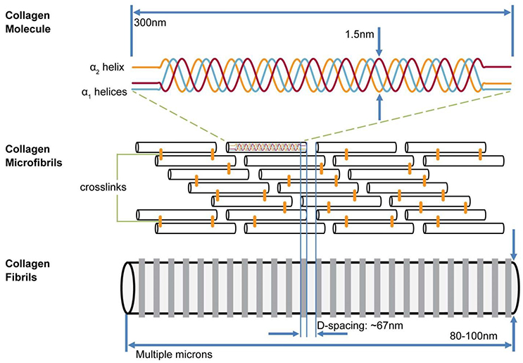
Figure 1. Model of hierarchical structure of collagen fibrils. Three helical (two α1, one α2) collagen molecules form a triple helix 300 nm long; these are assembled into a fibril containing a staggered array of helices with 40 nm gap between C and N termini of collinear helices. Gaps are aligned across width of collagen fibrils. Alongside each 40 nm wide “gap zone” (white) is a zone 27 nm wide in which no gaps exist (from Canelón and Wallace [13])
The first stage of bone formation is the creation of an assemblage of fibrils called osteoid, in which the fibrils are in contact. They are also in registry so that gap zones of any two adjacent fibrils are next to each other, thus continuing the gap zone/overlap zone structure over a scale of hundreds of nanometers. The links between fibrils may be proteoglycan molecules (specifically, glycosoaminoglycan, GAG) [14].
Mineral of Bone
Chemically, the mineral in bone has the composition of an apatite with a formula resembling Ca5 (PO4)3 OH (hydroxyapatite). X-ray diffraction (XRD) analysis of whole bone confirms that the mineral in bone is an apatite, although XRD alone cannot distinguish between the various members of the apatite family. Infra-red spectrometry shows the presence of significant amounts of carbonate substituting for both PO4 and OH [15]. Notably, bone mineral does not display a peak at 3,572 cm−1 for OH [16], although some amount of OH is detectable in NMR spectra [17].
When bone is attacked with an oxidant (bleach, hydrazine, etc.) the residual crystals viewed in TEM appear to be flake-like, with thickness of about 5 nm and maximum lateral dimensions of 20–50 nm [18]. Wide-angle X-ray scattering shows that the crystals are elongated along their crystallographic c-axis, with a length/width ratio of ~3 [19]. The flat surfaces of the flakes are formed by the 100 face of the apatite crystal [20], so that the c-axis must lie in the plane of the flakes.
Other Components of Bone
Besides collagen and apatite, bone contains other molecular components. About 10% of the organic matter of bone is a variety of non-collagenous proteins which play a role in the formation of bone. These include osteopontin, osteonectin, osteocalcin, bone sialoprotein, proteoglycans, matrix Gla protein, and alkaline phosphatases. Osteopontin appears to be the most abundant of these, and is associated with regions of growth in developing bone [21]. Proteoglycans are probably residual from the structure of osteoid. Some authors believe that one or more of these molecules could serve as a glue holding crystals together [22] although it is not clear which molecules are involved. Citrate is present in bone at a level of about 2 wt% [23] but its role is unclear; it has also been proposed to act as a glue between crystals [24]. The importance of this glue to a model for the strength of bone will be elaborated on later.
Three-Dimensional Organization of Bone at Nanoscale
TEM Imaging of Bone
In order to obtain satisfactory information about the 3D organization of the components of bone, it is essential that sections for TEM analysis are prepared in a way which does not disturb bone's nanostructure. In earlier studies of bone, sections of bone thin enough to be analyzed by TEM have been cut using a microtome equipped with a diamond knife [25, 26]. We have shown (Figure 10 in [11]) that this technique may seriously alter the appearance of the nanostructure of bone, specifically by shattering the main mineralized structural elements of bone to be described below. Therefore, studies of bone done prior to the introduction of ion-milling methods yielded images which gave incomplete information about the distribution of mineral in bone. Many previous TEM studies using microtome-cut sections of bone concluded that much of the mineral in bone resided in the gap zone between collinear triple helices of collagen (e.g., [27–31]). While there is a wide consensus that a large part of the mineral of bone must also lie outside the fibrils ([32–45]), the detailed structure of this extrabrillar component was poorly known before the use of ion milling for preparation of TEM samples.
Recently, researchers began to use ion milling techniques to prepare sections of bone and teeth for TEM studies [11, 42, 46, 47]. In these techniques, bone is gently eroded by bombardment with ions. In focused ion beam milling, Ga+ ions excavate a thin slice out of a polished surface. In ion milling, a pre-thinned disc of bone is slowly rotated in vacuum under two beams of Ar+ ions striking above and below the disc at low angles, until a hole appears. The edges of this hole are thin enough for use in TEM. Because no stress is applied to the sample in either of these methods, internal structures are not distorted or broken. By cooling the sample during milling, organic materials can be protected from damage, although some selective erosion of collagen has been observed.
Overall Structure of Bone
Orientation of Sections
Most bone is highly anisotropic. In preparing sections for TEM analysis it is important to select the orientation of the plane of the section in relation to the known anisotropy of the sample. In the analysis of long bones, which have been the subject of many TEM studies, sections cut perpendicular and parallel to the long axis of the bone yield fundamentally different views which provide complementary information about the overall 3D nanostructure of bone. Fibrils in long bones tend to be oriented at low angles with respect to the long axis of the bone. Cutting sections parallel or perpendicular to that long axis allow us to select either cross-sectional or longitudinal views of collagen fibrils and their associated minerals. Tomographic TEM analysis of sections [48], as well as use of a tilting stage in the microscope, allow us to make a link between the two sets of views.
Longitudinal Views
In all bright-field TEM images, areas of higher average mass appear darker due to stronger electron scattering. In bone, these represent areas where Ca and P are more abundant, either as mineral or as amorphous calcium phosphate. A typical section of a long bone of a mammal cut approximately parallel to the fibril axes is shown in Figure 2. Sections of bones of mammals ranging in size from mice to elephants look essentially similar to this view with very small differences in the scale of the component features.
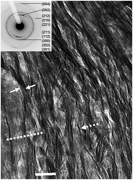
Figure 2. Longitudinal view of human femur: dashed arrow, single mineral lamella viewed edgewise; solid arrows enclose a stack of mineral lamellae; dashed line shows trace of a mineralized gap zone; scale = 50 nm. Inset: SAED (selected-area electron-diffraction) pattern from this section indexed for the apatite Bragg reflections; note that 002 reflection is in form of two arcs, showing partial preferred orientation of c-axes of apatite crystals parallel to the long-axis of bone.
The collagen fibrils are detectable through the presence of darker bands 40 nm in width and spaced every 67 nm which represent the gap zones. Note that the gap zones are in registry between adjacent fibrils over hundreds of nm. Oriented parallel to the fibrils are dark, highly mineralized features which extend for many hundreds of nm, although the precise termination of any such single feature is difficult to resolve. We have shown [11] that these are edge-on views of plates composed of apatite. We refer to these structures as mineral lamellae (MLs). Mineral lamellae viewed face-on (i.e., oriented with the plane of the plate parallel to the plane of the section) are also present in this view but not resolvable because they are electron-transparent in that orientation. An insert to Figure 2, focusing on a selected area electron diffraction pattern (SAED) for this section, shows that it is apatite. Note that the 002 reflection, from planes normal to the c-axis, is in the form of two arcs, indicating that the c-axes of apatite are oriented approximately parallel to the axes of the fibrils.
Figure 3 shows a view of such a section using both bright field (BF; Figure 3A) and dark-field (DF; Figure 3B) imaging, in the latter of which only electrons scattered from one Bragg reflection, in this case the 002 arc, are used to construct the image [49]. Anything illuminated in this view must be a crystal of apatite. We see that the mineral lamellae are not single crystals but are rather constructed of many single crystals in a slightly different crystallographic orientation with the result that some are illuminated and others are not. Notably, we observed that in DF images of longitudinal sections, the positions occupied by the gap zone were not selectively illuminated, although some crystals were visible where gap zones existed. We surmise that the crystals seen in these locations are from MLs that are fortuitously superimposed on the gap zones, while the gap zones themselves do not contain crystals of apatite large enough to Bragg scatter and light up in a DF image.
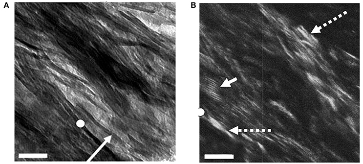
Figure 3. Bright- and dark-field views of same area in an ion-milled section of a bovine femur cut parallel to the long axis of the bone: (A) Bright field: white circle, reference point in both images; arrow, edge-wise view of single mineral lamella; (B) Dark-field image obtained using 002 reflection; dashed arrows, single crystals of apatite; solid arrow, Moiré fringes produced by two overlapping apatite crystals viewed face-on. Scale = 50 nm. From Schwarcz et al. [49]
From such DF views we have concluded that the MLs are actually mosaics of single crystals a few tens of nm across, and about 4–6 nm thick (Figure 4). When powdered bone is treated with an oxidizing agent such as bleach (NaClO) or hydrazine, the product is single flake-like crystals of apatite which are about 5 nm thick, and 20–50 nm across (Figure 4). No crystals are found adhering to one another in a planar array; this suggests that the crystals are held together in the MLs by some kind of organic glue.
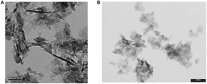
Figure 4. Isolated crystals extracted from bone using NaClO (bleach): (A) from experiments with E. McNally (unpublished); note that dark linear objects ~100 nm long are edge-wise views of fragments of mineral lamellae; most of the light-gray objects in the image are also ML fragments lying flat on the carbon grid. Scale =50 nm; (B) from Trueman et al. [50]. Some ML fragments are also present in this image. Smallest objects are single apatite crystals. Scale = 100 nm.
We have attempted to isolate single mineral lamellae from bone by treating it with ethylene diamine which dissolves only collagen but no other organic molecules [51, 52]. We obtained mainly stacks of mineral lamellae as well a small proportion of isolated MLs. On viewing these on a tilting stage, we were able to show that the distinctive edge-wise view of a mineralized structure ~5 nm in width was transformed into a plate containing multiple crystals (Figure 5) (Valente and Schwarcz, in preparation). The stacks resemble clusters of MLs seen in ion-milled sections of bone between adjacent collagen fibrils.
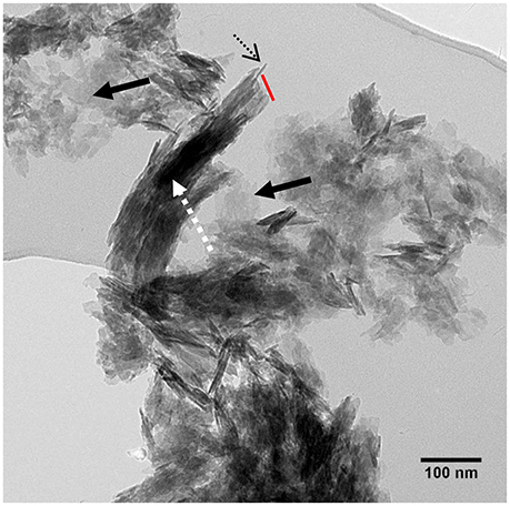
Figure 5. TEM view of stacks of mineral lamellae extracted from deproteinized bovine bone mounted on carbon grid: dashed arrow, stack of about 15 mineral lamellae; dotted black arrow, edgewise view of single ML in stack; red line, broken end of stack cutting across all MLs. Solid black arrows: single MLs lying flat on carbon grid. From Valente and Schwarcz, unpublished research.
Cross-Sectional Views
TEM images of bone that was sectioned perpendicular to the collagen fibril axes appear strikingly different from longitudinal views (Figure 6). Ion-milled sections have a lacy appearance in which electron-opaque structures partly curve around circular features of uniform diameter that appear to be holes in the section. Many of these circular features contain remnants of weakly electron-absorbing material which, when analyzed using electron energy loss spectroscopy (EELS), are shown to contain N as well as Ca and P (Luo, Binkley, Andrei, and Schwarcz, research in progress). Such composition indicates that they are cross-sections of collagen fibrils. The average radius of fibrils size ranges from 30 to 60 nm depending on the species of vertebrate.
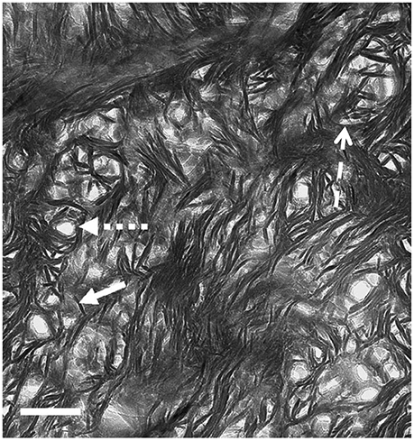
Figure 6. TEM view of ion milled section of bovine femur, with plane of section oriented normal to the axis of the bone (cross section). Small-dashed arrow, hole marking site of collagen fibril; solid arrow, single mineral lamella viewed end-on; large-dash arrow, mineral lamella wrapping around fibril. Scale = 100 nm. From Schwarcz [53].
The electron-opaque material wrapping around the fibrils is in the form of structures 4–6 nm thick and about 60–80 nm long. Some are curved to fit snugly around the fibril, or around another ML that is closer to the fibril. At greater distances from the fibril, these structures are straight, and clustered together in stacks. We conclude that these are views of mineral lamellae, seen in sections cutting across the long structures which were visible in the longitudinal sections.
Synthesis of Longitudinal and Cross-Sectional Views
It is apparent that the ~5 nm thick electron opaque objects visible in both cross- and longitudinal-sections are two aspects of the same objects, and that they must lie external to the fibrils. Note that a number of previous models of the ultrastructure of bone posited that most of the mineral in bone occurs inside the gap zone of the collagen fibrils, while a lesser amount is situated externally to the fibrils as mentioned in Section Overall Structure of Bone (Figure 7). We have shown that, in DF images of longitudinal sections, the mineral crystals do not appear to follow the gap zones but rather are oriented along the paths of mineral lamellae visible in BF images of the same section. Based on the synthesis of the information from longitudinal and cross-section views, we propose an alternative model as shown in Figure 8.
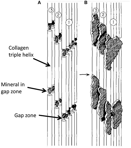
Figure 7. Schematic diagram showing progressive steps in mineralization of collagen molecules in a single fibril, assuming that most mineral in bone is intrafibrillar. (A) is earlier stage of mineralization with all mineral in gap zone; in (B), further mineralization extends into adjacent overlap zones. From Landis et al. [27].
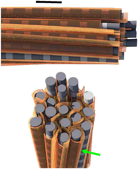
Figure 8. Conceptual model for the ultrastructure of bone, from Schwarcz et al. [49]. Scale = 100 nm.
The main aspects of this model relevant to the present discussion are as follows:
(a) Most (>80%) of the mineral in bone occurs in the form of flattened, elongated structures which extend for distances of more than 200 nm parallel to the long axes of the collagen fibrils.
(b) These structures (mineral lamellae) are mosaics of single apatite crystals whose thickness is the same as the thickness of the ML.
(c) Some of the mineral lamellae are curved into hemi-cylindrical forms which are wrapped part way around fibrils. The radius of curvature of these MLs increases with distance from the surface of the fibril.
(d) Still further away from the fibrils are straight (uncurved) MLs which are mainly arranged in stacks of 4–20 MLs. The space between adjacent MLs in a stack is <1 nm; there does not appear to be any other kind of material between adjacent MLs but molecules consisting of low atomic-weight elements (C,H,N,O) would be undetectable in TEM.
(e) A significant amount of Ca and P occurs within the collagen fibrils, in the gap zone where its presence can be detected using EELS [43]. However, this does not appear to be in the form of crystals of apatite.
The stacks of straight or slightly curved mineral lamellae have been observed isolated from bone (Valente and Schwarcz, unpublished). They appear to be broken off at one end (Figure 5), presumably because they were subjected to loading stress during preparation of the particles for viewing. The stacks of lamellae always break across the stack and do not delaminate. The implication is that there is a strong bond acting between the lamellae. This could be a molecular “glue” attached to the surfaces of adjacent lamellae in the stack. The absence of stacks of lamellae in samples prepared using an oxidant implies that the glue is also oxidized. This glue should contribute to the overall strength of bone. The presented experimental observations provide new insights into bone.
The observations that most of minerals are extrafibrillar agree with selected TEM studies mentioned in Section TEM Imaging of Bone. Also, the notion of extrafibrillar minerals in the form of a foam or a polycrystal was proposed by Hellmich and Ulm [40, 54] on mechanical grounds. Later modeling papers provided further support for extrafibrillar fibers [10, 55], motivated by imaging studies (e.g., [56, 57]). However, the ideas of multiple concentric lamellae surrounding collagen fibril or parallel lamellae between mineralized fibrils are novel. Additional insights on these geometries can be obtained by modeling. In next section we will focus on modeling of a mineralized collagen fibril with multiple concentric mineral lamellae.
Modeling of Bone at Nanoscale
Various Geometric Models
The collagen-mineral model of bone at the nanoscale is of high scientific and practical importance. This nanoscale unit is a building block of bone from which the hierarchical structure of bone forms, leading to a material which is strong, stiff, tough and lightweight.
Knowledge of the collagen-mineral arrangement is needed to create nanoscale models which can serve as inputs for hierarchical or multiscale models of bone. Due to the very small scales involved, the experimental characterization of bone at the nanoscale is challenging. In Section Three-Dimensional Organization of Bone at Nanoscale, we described TEM results on imaging of the bone nanostructure. Experimental validation of the mechanical properties of bone at the nanoscale is also very challenging. Relevant experimental studies include atomic force microscopy measurements combined with electron microscopy imaging (SEM and TEM) (e.g., [58–60]) and tests on micro-pillars of bone at a μm scale [61–63]. Theoretical models can give valuable insights on bone's response at the nanoscale and the structure-property relations of bone in general. Such knowledge is needed to understand the mechanisms that lead to the overall properties of bone and how the hierarchical structure of bone is affected by various factors such as age, disease, diet, exercise, and others. This information can also lead to improved diagnostic tools and can guide bone treatments.
Numerous theoretical models of bone at the nanoscale have been proposed, as summarized in the review papers by Hamed and Jasiuk [64] and Sabet et al. [65], among others. They range from analytical models involving strength of materials and micromechanics models to computational studies including atomic level simulations using molecular dynamics and continuum level studies utilizing a finite element method. Most of these models assume two constituents of bone, collagen and apatite crystals, while a few also include non-collagenous proteins and water. The mechanics models need as inputs the composition and properties of the constituents as well as the mineral-collagen spatial arrangement. Most of the modeling studies of bone at the nanoscale assumed that the crystals are isolated and embedded within a collagen fibril (e.g., [29, 31, 66–69]). The most cited model, proposing a staggered arrangement of crystals in a collagen fibril, is due to Jäger and Fratzl [70]. Fewer studies employed models in which minerals are also present on the outside of the collagen fibril (e.g., [40, 54, 71–75]).
In this paper, we study computationally the novel geometric model of a mineralized collagen fibril, described in Section Three-Dimensional Organization of Bone at Nanoscale and shown in Figure 8, involving the extrafibrillar mineral lamellae encircling a collagen fibril, and compare it with a classical model involving isolated minerals in a collagen fibril. Such newly proposed geometrical arrangement of collagen and apatite crystals at the nanoscale should have a significant impact on the mechanical properties of bone at the nanoscale and higher scales.
Finite Element Modeling
We study computationally two geometrical models of mineral-collagen arrangement in bone at the nanoscale. We compare mechanical properties computed using the classical model involving isolated staggered minerals within a collagen fibril, called Model I, and the proposed model involving extrafibrillar crystals arranged into mineral lamellae on the outer shell of a collagen fibril, referred to as Model II. The second model follows the TEM observations summarized in Section Three-Dimensional Organization of Bone at Nanoscale. A more comprehensive analysis was done in Abueidda et al. [76] where we compared these two geometric models by considering plane stress (thin sheet), plane strain (thick sheet), and axisymmetric (rotation about the long axis of collagen fibril) cases. Since the mineralized collagen fibril has a three-dimensional (3D) structure, in this paper we focus on the axisymmetric case only, as it may more closely reflect the 3D case than the plane cases. Furthermore, the Model II involves two interfacial cases: one involving a soft matrix (interphase) between the mineral lamellae and one with no matrix (interphase) layer. The Model I and the two versions of the Model II are sketched in Figure 9.
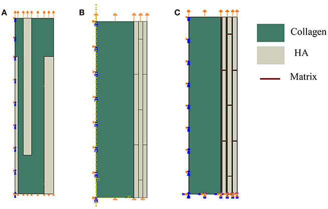
Figure 9. Geometrical models of bone at the nanoscale. Model I: (A) isolated staggered minerals, Model II: (B) mineral lamellae with no matrix, and (C) mineral lamellae with matrix (interphase).
In the Model I, shown in Figure 9A, the mineral platelets have length of 100 nm, total radius is 14 nm, and variable thickness (1, 3, and 3.42 nm) with values increasing with distance from the center. In the Model II the minerals are also 100 nm in length. For the case of no matrix (interphase) between mineral lamellae, shown in Figure 9B, the radius of the collagen fibril is 30 nm while thicknesses of mineral lamellae are 3.435 nm and for the case of matrix (interphase) between the mineral lamellae, shown in Figure 9C, the radius of the collagen fibril is 31 nm, the thickness of ML is 4 nm and the matrix (interphase) between them is 1 nm. The mineral dimensions are chosen to reflect the 45% volume fraction of minerals.
In the analysis we employ the finite element method using a commercial software Abaqus [77]. Biquadratic 8-node axisymmetric quadrilateral elements (CAX8R), available in the Abaqus library, are used in simulations. Meshes are refined until results are not sensitive to decreased mesh sizes. Model I (Figure 9A) has 25,000 elements, while the Model II (Figure 9B) with no interphase has 14,400 elements and the model II (with interphase) (Figure 9C) has 126,000 elements. We assume that the main damage mechanism is sliding and debonding at collagen-mineral interfaces. We model sliding and debonding by using cohesive surface elements. We model the interfaces by using a surface-based cohesive behavior model, available in Abaqus [77] (see tutorial 37.1.10), which assumes that the interface thickness is negligibly small [78, 79]. Schematic of the traction-separation law, used in this model is given in Figure 10. Normal traction-displacement law (opening/debonding mode) and tangential traction-deformation relation (sliding mode) are illustrated in Figures 10A,B, respectively.
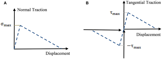
Figure 10. Schematic of a traction-separation law using in finite element simulations. (A) Opening mode (normal traction-deformation) and (B) sliding mode (tangential traction-deformation).
In the interfacial model, variables include the stiffness, strength and damage characteristics of the interface in the normal and transverse directions. These parameters have been computed using molecular dynamics simulations and recently measured experimentally by [80]. In the analysis, we use the values reported in Luo et al. [69] which align with the data of [80]. Further details of the model include assumptions about the mineral-mineral interfaces in the mineral lamellae. Here, we consider two cases, one involving mineral-mineral interfaces connected via the traction-separation interface model and one assuming a protein layer between the mineral lamellae and taking the properties of that layer same as of the collagen, for simplicity. This layer could physically represent non-collagenous proteins, as mentioned in Section Three-Dimensional Organization of Bone at Nanoscale.
In the analysis, we assume that the apatite crystals and collagen are linear elastic and isotropic. Collagen fibril has elastic modulus E = 1.0 GPa and Poisson's ratio v = 0.3 while minerals have E = 110 GPa and v = 0.3. In the literature, the elastic modulus of collagen ranges from less than unity to about 11 GPa, while the modulus of elasticity of apatite spans 60–180 GPa. Our selected values are in the mid-range of these values.
We compute the overall longitudinal stress-strain response for the Models I and II. We use mixed boundary conditions which include symmetric boundary conditions along the axis of rotation, zero tractions on lateral sides, zero displacement in the vertical direction and zero tangential traction at the bottom surface, and applied displacement in the vertical/longitudinal direction and zero tangential traction, as shown schematically in Figure 9.
In order to investigate the effect of interfacial bonding, we vary the total fracture energy in the range 0.01–1.0 J/m2 and assign the strength of the interface as 30 and 64 MPa and the stiffness of interface as 80 GPa, following Luo et al. [69]. The total fracture energy value agrees well with recent measurements of [80]. In the analysis, we assume that failure will take place in the interface by sliding or debonding and we do not allow collagen nor crystals to fail in the model, for simplicity.
Finite Element Modeling Results
Finite element computations provide results on the longitudinal tensile elastic modulus and strength for the Model I (consisting of interfibrillar isolated minerals) and Model II (with mineral lamellae with or without the matrix/interphase). A clear difference can be observed between the Models I and II, with the Model II having higher mechanical properties. Figure 11 shows the longitudinal tensile elastic moduli under different geometrical conditions, assuming the strength of the interface as 64 MPa, and the fracture energy of 0.2 J/m2. The Model I gives the elastic modulus of 14.4 GPa while the Model II gives values of nearly 49.4 GPa for the no matrix/interphase case and 35.7 GPa for the case when interphase (matrix) is included between mineral lamellae. A similar trend can be seen in Figure 12 which illustrates the longitudinal tensile strength for the three models, showing again an advantage of the Model II. In addition, Figure 12 shows a strong effect of the fracture energy of the interface on the longitudinal tensile strength. The strength of the Model I ranges from 150 to 250 MPa while the strength of the Model II spans from 150 to nearly 350 MPa, depending on the interfacial fracture energy. Stress-strain curves are presented in Figure 13. Note that the Model II with no interphase shows highest stiffness and strength while Model I gives highest strain at failure.
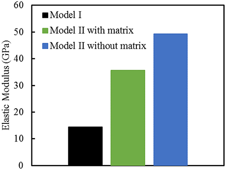
Figure 11. Longitudinal tensile elastic moduli for different geometric models of bone. The strength of the interface is 64 MPa, and the fracture energy is 0.2 J/m2.
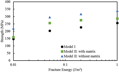
Figure 12. Effect of fracture energy on the longitudinal tensile strength for different geometric models of bone. The strength of the interface is 64 MPa.
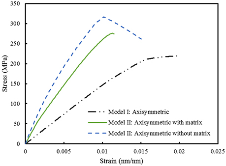
Figure 13. Comparison between Model I and Model II. The strength of the interface is 64 MPa while the fracture energy is 0.2 J/m2.
Discussion of Finite Element Results
We computed and compared mechanical properties of bone at the nanoscale using the classical model involving isolated staggered minerals within a collagen fibril (Model I) and the new model with all crystals being in the mineral lamellae on the outer shell of a collagen fibril (Model II). In the analysis, we used the assumption of axisymmetry, for simplicity. Note that the axisymmetry implies a 360 degree rotation about the axis of the fibril. Thus, the axisymmetric case is a good representation of the 3D geometry for the ML case since that model involves concentric cylinders which encircle a collagen fibril. The staggered mineral arrangement model, in the axisymmetric representation, implies that isolated minerals are in the form of finite circular hollow cylinders embedded within a collagen fibril which is different than the small isolated minerals. However, based on the study of Yuan et al. [68] of the model with staggered arrangement of minerals, longitudinal elastic moduli are not very sensitive to a 3D arrangement of crystals.
The results for longitudinal tensile elastic modulus, shown in Figure 11, are reported for a given interfacial condition. However, the elastic modulus is independent of interface parameters, as expected, and also shown computationally in Abueidda et al. [76]. The Model I gives lowest value of elastic modulus (14.4 GPa) while the Model II without interphase gives a three times higher stiffness (nearly 50 GPA). This value is close to an upper bound (rule of mixtures, or Voigt model) given by:
where E denotes elastic modulus, V is a volume fraction. Substituting in this expression 0.45 for volume fraction of mineral (Vmineral), and elastic moduli as Ecollagen = 1.0 GPa and Emineral = 110 GPa gives Elongitudinal = 50 GPa. This is in close agreement to the value of 49.4 computed by the finite element analysis. The Model I, which involves a collagen matrix reinforced by apatite crystals, gives lowest value. Minerals stiffen soft matrix as they partially carry the load but the behavior is governed by the matrix. The Model II with the matrix (interphase) gives an intermediate value. It benefits from the mineral core (like in the Model II with no matrix) but the mineral lamellae have characteristics of the Model I (crystals are staggered with the matrix in between).
The longitudinal elastic modulus predicted by the Model I is on a low side. Numerous nanoindentation experiments report values ranging from 15 to 30 GPa. These experiments are done at a microscale, which already includes some porosity. Micropillar experiments of Luczynski et al. [62], which give modulus of about 30 GPa, agree most closely with the Model II with matrix (interphase). Further experiments are needed to learn about the interfaces between the mineralized lamellae.
What are the implications of each of these two models: mineralized lamellae encircling the collagen fibril vs. the isolated minerals located inside a collagen fibril? At the macroscale, whole long bones are hollow shafts where a cortical bone is forming a stiff outer shell. Such geometry is optimized by nature to yield a stiff, strong and yet lightweight material. From a structural mechanics perspective a hollow geometry gives stronger and stiffer response in bending and torsion, for the same bone tissue volume. In fact, older bone becomes thinner and has larger radius in a cross-section. Such architecture minimizes weight and maximizes mechanical performance. The proposed nanoscale model has similar features but at a much smaller scale. Mineral sheets encircling collagen fibril should give the mineralized collagen fibril higher bending and torsional stiffness and thus allow it to withstand higher loads.
Note that in our computational model we assumed only interfacial failures. Thus, our simulations did not allow the failure of bone's components: collagen and minerals. The computed strengths reflect that assumption. Thus, the results provide a comparative study between these different geometric models of bone, subject to this limitation. Extension of this study, accounting for failure of collagen and minerals is needed for a direct comparison with experiments (e.g., [59]).
Also, bone is mainly loaded in compression. The Model II is expected to have a better compressive response since collagen has a lower capacity to withstand compression. Nair et al. [74] studied the staggered mineral arrangement (Model I) and concluded that the collagen fibril with interfibrillar minerals only is not sufficient to withstand the experimentally predicted compressive behavior.
This computational study has several limitations.
(1) Idealized axisymmetric model was used. Lamellar mineral structures surrounding the collagen fibrils were modeled as solid cylinders, rather than as discrete but connected minerals.
(2) Boundary conditions were idealized with tractions assumed to be zero on side boundary. More realistic boundary conditions should account for presence of other mineralized fibrils.
(3) Interface parameters were chosen based on those found in literature. It is not clear whether these are realistic values for collagen-mineral interfaces in bone as experiments are limited.
(4) Idealized linear elastic constitutive models were used for collagen and mineral phases with no plasticity, creep or fracture allowed in these two phases.
(5) Damage was only assumed in the form of sliding and debonding at the collagen-mineral interfaces.
(6) Collagen fibril in the Model II had no interfibrillar minerals present although some mineral may be present there (estimated 20%).
(7) Only tensile longitudinal constitutive response was computed.
Further theoretical and experimental studies can be done to address these idealizations for the studied model.
This computational study of bone at the nanoscale complements other modeling studies which incorporated elastoplasticity [81], creep [82] and poroelasticity [55] and more complex 3D geometries of collagen structures within the collagen fibril [83–86], cross-linking between collagen fibrils [67], and formulated molecular dynamics models [87]. Extensions of such constitutive models and theoretical frameworks to the lamellar model presented in this paper would further advance understanding of the proposed model and the mechanical behavior of bone at the nanoscale and higher scales.
Summary
We summarized our recent transmission electron microscopy observations pointing out to an alternate collagen-mineral arrangement in bone at the nanoscale. This model proposes mineral lamellae surrounding outer surfaces of collagen fibrils, as opposed to minerals being mainly embedded in a collagen fibril. Secondly, we used this model of the mineral lamellae (representing connected minerals outside collagen fibrils) and compared its mechanical properties with those of a classical model involving isolated minerals situated inside the collagen fibril. We conducted this analysis computationally, using a finite element method with cohesive surface elements at collagen-mineral interfaces. Significant improvements in stiffness and strength were found for the new model, when compared with the isolated minerals model, and closer comparison with experiments was achieved. This research brings a new perspective on the structure and mechanical properties of bone at the nanoscale.
Author Contributions
HS did TEM imaging and wrote the experimental part of this paper (Sections Introduction, The Components of Bone, Three-Dimensional Organization of Bone at Nanoscale). DA is a graduate student, advised by IJ, and he did computational modeling. IJ wrote computational part of the paper (Section Modeling of Bone at Nanoscale). All authors contributed to the overall editing of the paper and approved the final version.
Conflict of Interest Statement
The authors declare that the research was conducted in the absence of any commercial or financial relationships that could be construed as a potential conflict of interest.
Acknowledgments
This research was partially supported by the National Science Foundation DMR Program Grant 15-07169 (IJ). Computations were done at the Visualization Lab at Beckman Institute at the University of Illinois. TEM analyses were supported by a grant to HS from the Natural Sciences and Engineering Research Council of Canada (HS). HS thanks Andrew Valente and Beth McNally for permission to include unpublished figures.
References
1. Rho JY, Kuhn-Spearing L, Zioupos P. Mechanical properties and the hierarchical structure of bone. Med Eng Phys. (1998) 20:92–102. doi: 10.1016/S1350-4533(98)00007-1
2. Olszta MJ, Cheng X, Jee SS, Kumar R, Kim YY, Kaufman MJ, et al. Bone structure and formation: a new perspective. Mater Sci Eng R Rep. (2007) 58:77–116. doi: 10.1016/j.mser.2007.05.001
3. Reznikov N, Shahar R, Weiner S. Bone hierarchical structure in three dimensions. Acta Biomater. (2014a) 10:3815–326. doi: 10.1016/j.actbio.2014.05.024
4. Weiner S, Wagner HD. The material bone: structure mechanical function relations. Annu Rev Mater Sci. (1998) 28:271–98.
6. Klein-Nulend J, Bonewald LF. The osteocyte. In: Bilezekian J, Raisz L, Martin, TJ, editors. Principles of Bone Biology. 3rd ed. Cambridge, MA: Academic Press (2008) 153–174.
7. Giraud-Guille M M. Twisted plywood architecture of collagen fibrils in human compact bone osteons. Calcif Tissue Int. (1988) 42:167–80. doi: 10.1007/BF02556330
8. Reznikov N, Shahar R, Weiner S. Three-dimensional structure of human lamellar bone: the presence of two different materials and new insights into the hierarchical organization. Bone (2014b) 59:93–104. doi: 10.1016/j.bone.2013.10.023
9. Lees S. Considerations regarding the structure of the mammalian mineralized osteoid from viewpoint of the generalized packing model. Conn. Tiss. Res. (1988) 6:281–303.
10. Fritsch A, Hellmich C. ‘Universal’ microstructural patterns in cortical and trabecular, extracellular and extravascular bone materials: micromechanics-based prediction of anisotropic elasticity. J Theor Biol. (2007) 224:597–620. doi: 10.1016/j.jtbi.2006.09.013
11. McNally EA., Schwarcz HP, Botton GA, Arsenault L. A model for the ultrastructure of bone based on electron microscopy of ion-milled sections. PLoS ONE (2012) 7:e29258. doi: 10.1371/journal.pone.0029258
12. Orgel J, Irving T, Miller A, Wess T. Microfibrillar structure of type I collagen in situ. Proc Natl Acad Sci U.S.A. (2006) 103:9001–5. doi: 10.1073/pnas.0502718103
13. Canelón SP, Wallace JM. β-Aminopropionitrile-induced reduction in enzymatic crosslinking causes in vitro changes in collagen morphology and molecular composition. PLoS ONE (2016) 11:e0166392. doi: 10.1371/journal.pone.0166392
14. Orgel J, Eid A, Antipova O, Bella J, Scott JE. Decorin Core Protein (Decoron) shape complements collagen fibril surface structure and mediates its binding. PLoS ONE (2009) 4:e7028. doi: 10.1371/journal.pone.0007028
15. Rey C, Miquel J, Facchini L, Legrand A., Glimcher MJ. Hydroxyl groups in bone mineral. Bone (1995) 16:583–6. doi: 10.1016/8756-3282(95)00101-I
16. Pasteris JD, Wopenka B, Freeman JJ, Rogers K, Valsami-Jones E, van der Houwen JAM, et al. Lack of OH in nanocrystalline apatite as a function of degree of atomic order: implications for bone and biomaterials. Biomaterials (2004) 25:229–38. doi: 10.1016/S0142-9612(03)00487-3
17. Wang Y, Von Euw S, Fernandes FM, Cassaignon S, Selmane M, Laurent G, et al. Water-mediated structuring of bone apatite. Nat Mater. (2013) 12:1144–53. doi: 10.1038/nmat3787
18. Weiner S, Price PA. Disaggregation of bone into crystals. Calcif Tiss Internat. (1986) 393:65–375. doi: 10.1007/BF02555173
19. Turunen MJ, Kaspersen JD, Olsson U, Guizar-Sicairos M, Bech M, Schaff F, et al. Bone mineral crystal size and organization vary across mature rat bone cortex. J Struc Biol. (2016) 195:337–44. doi: 10.1016/j.jsb.2016.07.005
20. Moradian-Oldak J, Weiner S, Addadi L, Landis WJ, Traub W. Electron imaging and diffraction study of individual crystals of bone, mineralized tendon and synthetic carbonate apatite. Conn Tiss Res. (1991) 25:219–28. doi: 10.3109/03008209109029158
21. McKee MD, Nanci A. Osteopontin at mineralized tissue interfaces in bone, teeth, and osseointegrated implants: ultrastructural distribution and implications for mineralized tissue formation, turnover, and repair. Microsc Res Tech. (1996) 33:141–64.
22. Fantner GE, Hassenkam T, Kindt JH, Weaver JC, Birkedal H, Pechenik L, et al. Sacrificial bonds and hidden length dissipate energy as mineralized fibrils separate during bone fracture. Nat Mater (2005) 4:612–6. doi: 10.1038/nmat1428
23. Schwarcz HP, Agur K, Jantz LM. A new method for determination of post- mortem interval: citrate content of bone. J For Sci. (2011) 55:1516–22. doi: 10.1111/j.1556-4029.2010.01511.x
24. Davies E, Müller KH, Wong WC, Pickard CJ, Reid DG, Skepper JN, et al. Citrate bridges between mineral platelets in bone. Proc Natl Acad Sci U.S.A. (2014) 111:E1354–63. doi: 10.1073/pnas.1315080111
26. Fernandez-Moran H. A diamond knife for ultrathin sectioning. Exp Cell Res. (1953) 5:255–6. doi: 10.1016/0014-4827(53)90112-8
27. Landis WJ, Song MJ, Leith A, McEwen L, McEwen BF. Mineral and organic matrix interaction in normally calcifying tendon visualized in three dimensions by high-voltage electron microscopic tomography and graphic image reconstruction. J Struct Biol. (1993) 110:39–54. doi: 10.1006/jsbi.1993.1003
28. Landis WJ, Hauschka BT, Rogerson CA, Glimcher MJ. Electron microscopic observations of bone tissue prepared by ultracryomicrotomy. J Ultrastruct Res. (1977) 59:185–206. doi: 10.1016/S0022-5320(77)80079-8
29. Arsenault AL. A comparative electron microscopic study of apatite crystals in collagen fibrils of rat bone, dentin and calcified turkey leg tendons. Bone Miner. (1989) 6:165–77. doi: 10.1016/0169-6009(89)90048-2
30. Lee DD, Glimcher MJ. Three-dimensional spatial relationship between the collagen fibrils and the inorganic calcium phosphate crystals of pickerel (Americanus americanus) and herring (Clupea harengus) bone. J. Mol. Biol. (1991) 217:487–501. doi: 10.1016/0022-2836(91)90752-R
31. Weiner S, Arad T, Traub W. Crystal organization in rat bone lamellae. FEBS Lett. (1991) 285:49–54. doi: 10.1016/0014-5793(91)80722-F
32. Bonar LC, Lees S, Mook HA. Neutron diffraction studies in collagen in fully mineralized bone. J Mol Biol. (1985) 181:265–70. doi: 10.1016/0022-2836(85)90090-7
33. Lees S, Bonar LC, Monk HA. A study of dense mineralized tissue by neutron diffraction. Int J Biol Macromol. (1984) 6:321–6. doi: 10.1016/0141-8130(84)90017-5
34. Lees S, Prostak K. The locus of mineral crystallites in bone. Connect Tissue Res. (1988) 18:41–54. doi: 10.3109/03008208809019071
35. Landis WJ, Song MJ. Early mineral deposition in calcifying tendon characterized by high voltage electron microscopy and 3-dimensional graphic imaging. J Struct Biol. (1991) 107:116–27. doi: 10.1016/1047-8477(91)90015-O
36. Lees S, Prostak KS, Ingle VK, Kjoller K. The loci of mineral in turkey leg tendon as seen by atomic force microscope and electron microscopy. Calcif Tissue Int. (1994) 55:180–9.
37. Landis WJ, Hodgens KJ, Song MJ, Arena J, Kiyonaga S, Marko M, et al. Mineralization of collagen may occur on fibril surfaces: evidence from conventional and high-voltage electron microscopy and three-dimensional imaging. J Struct Biol. (1996) 117:24–35. doi: 10.1006/jsbi.1996.0066
38. Prostak KS, Lees S. Visualization of crystal-matrix structure. In situ mineralized turkey leg tendon and bone. Calcif Tissue Int (1996) 59:474–9. doi: 10.1007/BF00369213
39. Sasaki N, Tagami A, Goto T, Taniguchi M, Nakata M, Hikichi K. Atomic force microscopic studies on the structure of bovine femoral cortical bone at the collagen fibril–mineral level. J Mater Sci Mater Med. (2002) 13:333–7. doi: 10.1023/A:1014079421895
40. Hellmich C, Ulm F-J. Average hydroxyapatite concentration is uniform in the extracollagenous ultrastructure of mineralized tissues: evidence at the 1–10-μm scale. Biomech Models Mechanobiol (2003) 2:21–36. doi: 10.1007/s10237-002-0025-9
41. Hassenkam T, Fantner GE, Cutroni JA, Weaver JC, Morse DE, Hansma PK. High-resolution AFM imaging of intact and fractured trabecular bone. Bone (2004) 35:4–10. doi: 10.1016/j.bone.2004.02.024
42. Jantou V, Turmaine M, West GD, Horton MA, McComb DW. Focused ion beam milling and ultramicrotomy of mineralized ivory dentine for analytical transmission electron microscopy. Micron (2009) 40:495–501. doi: 10.1016/j.micron.2008.12.002
43. Jantou-Morris V, Horton MA, McComb DW. The nano-morphological relationships between apatite crystals and collagen fibrils in ivory dentine. Biomaterials (2010) 31:5275–86. doi: 10.1016/j.biomaterials.2010.03.025
44. Alexander B, Daulton TL, Genin GM, Lipner J, Pasteris JD, Wopenka B, et al. The nanometre-scale physiology of bone: steric modelling and scanning transmission electron microscopy of collagen–mineral structure. J R Soc Interface (2012) 9:1774–86. doi: 10.1098/rsif.2011.0880
45. Su X, Sun K, Cui FZ, Landis WJ. Organization of apatite crystals in human woven bone. Bone (2003) 32:150–62. doi: 10.1016/S8756-3282(02)00945-6
46. Cressey B, Cressey G. A model for the composite nanostructure of bone suggested by high-resolution transmission electron microscopy. Min Mag. (2003) 67:1171–82. doi: 10.1180/0026461036760156
47. Nalla RK, Porter AE, Daraio C, Minor AM, Radmilovic V, Stach EA, et al. Ultrastructural examination of dentin using focused ion-beam cross-sectioning and transmission electron microscopy. Micron (2005) 36:672–80. doi: 10.1016/j.micron.2005.05.011
48. McNally EA, Nan F, Schwarcz HP, Botton G. Scanning transmission electron microscopic tomography of cortical bone using Z-contrast imaging. Micron (2013) 49:46–53. doi: 10.1016/j.micron.2013.03.002
49. Schwarcz HP, McNally EA, Botton GA. Dark-field transmission electron microscopy of cortical bone reveals details of extrafibrillar crystals. J Struc Biol. (2014) 188:240–8. doi: 10.1016/j.jsb.2014.10.005
50. Trueman CNG, Behrensmeyer AK, Tuross N, Weiner S. Mineralogical and compositional changes in bones exposed on soil surfaces in Amboseli National Park, Kenya: diagenetic mechanisms and the role of sediment pore fluids. J Archaeol Sci. (2004) 31:721–39. doi: 10.1016/j.jas.2003.11.003
51. Peckham S, Losee FL, Ettleman I. Ethylenediamine versus potassium hydroxide-glycol in the removal of organic matter from dentine. J. Dent. Res. (1956) 35:947–9.
52. Williams JB, Irvine JW. Preparation of the inorganic matrix of bone. Science (1954) 119:771–2. doi: 10.1126/science.119.3100.771
53. Schwarcz HP. The ultrastructure of bone as revealed in electron microscopy of ion-milled sections. Semin Cell Dev Biol. (2015) 46:44–50. doi: 10.1016/j.semcdb.2015.06.008
54. Hellmich C, Ulm F-J. Micromechanical model for ultrastructural stiffness of mineralized tissues. J Eng Mechanics (2002) 128:898–908. doi: 10.1061/(ASCE)0733-9399(2002)128:8(898)
55. Morin C, Hellmich C. A multiscale poromechanical approach to wave propagation and atenuation in bone. Ultrasonics (2014) 54:1251–69. doi: 10.1016/j.ultras.2013.12.005
56. Anderson HC, Garimella R, Tague SE. The role of matrix vesicles in growth plate development and biomineralization. Front Biosci. (2005) 10:822–37. doi: 10.2741/1576
57. Hong SI, Hong SK, Kohn DH. Nanostructural analysis of trabecular bone. J Mater Sci Mater Med. (2009) 20:1419–26. doi: 10.1007/s10856-009-3708-2
58. Wallace JM. Applications of atomic force microscopy for the assessment of nanoscale morphological and mechanical properties of bone. Bone (2012) 50:420–7. doi: 10.1016/j.bone.2011.11.008
59. Hang F, Barber AH. Nano-mechanical properties of individual mineralized collagen fibrils from bone tissue. J R Soc Interface (2011) 8:500–5. doi: 10.1098/rsif.2010.0413
60. Jimenez-Palomar I, Shipov A, Shahar R, Barber AH. Mechanical behavior of osteoporotic bone at sub-lamellar length scales. Front Mater. (2015) 2:9. doi: 10.3389/fmats.2015.00009
61. Schwiedrzik J, Raghavan R, Burki A, LeNader V, Wolfram U, Michler J, et al. In situ micro pillar compression reveals superior strength and ductility but an absence of damage in lamellar bone. Nat Mater. (2014) 13:740–7. doi: 10.1038/nmat3959
62. Luczynski KW, Steiger-Thirsfeld A, Bernardi J, Eberhardsteiner J, Hellmich C. Extracellular bone matrix exhibits hardening elastoplasticity and more than double cortical strength: evidence from homogeneous compression of non-tapered single micron-sized pillars welded to a rigid substrate. J Mech Behav Biomed Mater. (2015) 52:51–62. doi: 10.1016/j.jmbbm.2015.03.001
63. Tertuliano OA, Greer JR. The nanocomposite nature of bone drives its strength and damage resistance. Nat Mater. (2016) 15:1195–202. doi: 10.1038/nmat4719
64. Hamed E, Jasiuk I. Elastic modeling of bone at nanostructural level. Mater Sci Engi R Rep. (2012) 73:27–49. doi: 10.1016/j.mser.2012.04.001
65. Sabet F, Najafi Raeisi A, Hamed E, Jasiuk I. Modelling of bone fracture and strength at different length scales–a review. Interface Focus (2016). 6:20150055. doi: 10.1098/rsfs.2015.0055
66. Kotha SP, Guzelsu N. The effects of interphase and bonding on the elastic modulus of bone: changes with age-related osteoporosis. Med Eng Phys. (2000) 22:575–85. doi: 10.1016/S1350-4533(00)00075-8
67. Siegmund T, Allen MR, Burr DB. Failure of mineralized collagen fibrils: modeling the role of collagen cross-linking. J. Biomech. (2008) 41:1427–35. doi: 10.1016/j.jbiomech.2008.02.017
68. Yuan F, Stock SR, Haeffner DR, Almer JD, Dunand DC, Brinson LC. A new model to simulate the elastic properties of mineralized collagen fibril, Biomech. Model Mechanobiol. (2011) 10:147–60. doi: 10.1007/s10237-010-0223-9
69. Luo Q, Nakade R, Dong X, Rong Q, Wang X. Effect of mineral-collagen interfacial behavior on the microdamage progression in bone using a probabilistic cohesive finite element model. J Mech Behav Biomed Mater. (2011) 4:943–52. doi: 10.1016/j.jmbbm.2011.02.003
70. Jäger I, Fratzl P. Mineralized collagen fibrils: a mechanical model with a staggered arrangement of mineral particles. Biophys. J. (2000) 79:1737–46. doi: 10.1016/S0006-3495(00)76426-5
71. Pidaparti R, Chandran A, Takano Y, Turner C. Bone mineral lies mainly outside collagen fibrils: predictions of a composite model for osternal bone. J Biomech. (1996) 29:909–16. doi: 10.1016/0021-9290(95)00147-6
72. Hellmich C, Barthélémy J-F, Dormieux L. Mineral–collagen interactions in elasticity of bone ultrastructure–a continuum micromechanics approach. Eur J Mech. (2004) 23:783–810. doi: 10.1016/j.euromechsol.2004.05.004
73. Nikolov S, Raabe D. Hierarchical modeling of the elastic properties of bone at submicron scales: the role of extrafibrillar mineralization. Biophys J. (2008) 94:4220–32. doi: 10.1529/biophysj.107.125567
74. Nair AK, Gautieri A, Buehler MJ. Role of intrafibrillar collagen mineralization in defining the compressive properties of nascent bone. Biomacromolecules (2014) 15:2494–500. doi: 10.1021/bm5003416
75. Lin L, Samuel J, Zeng X, Wang X. Contribution of extrafibrillar matrix to the mechanical behavior of bone using a novel cohesive finite element model. J Mech Behav Biomed Mater. (2017) 65:224–35. doi: 10.1016/j.jmbbm.2016.08.027
76. Abueidda D, Sabet FA, Jasiuk I. Modeling of stiffness and strength of bone at nanoscale. J. Biomech Eng. (2017) 139:051006-1-10. doi: 10.1115/1.4036314
78. Benzeggagh ML, Kenane M. Measurement of mixed-mode delamination fracture toughness of unidirectional glass/epoxy composites with mixed-mode bending apparatus. Compos Sci Technol. (1996) 56:439–49.
79. Camanho PP, Davila C. Mixed-mode decohesion finite elements for the simulation of delamination in composite materials. Tech. Rep. NASA/TM-2002-211737, NASA (2002).
80. Hang F, Gupta HS, Barber AH. Nanointerfacial strength between non-collagenous protein and collagen fibrils in antler bone. J R Soc Interface (2014) 11:20130993. doi: 10.1098/rsif.2013.0993
81. Morin C, Vass V, Hellmich C. Micromechanics of elastoplastic porous polycrystals: theory, algorithm, and application to osteonal bone. Int J Plasticity (2017) 91:238–67. doi: 10.1016/j.ijplas.2017.01.009
82. Eberhardsteiner L, Hellmich C, Scheiner S. Layered water in crystal interfaces as source for bone viscoelasticity: arguments from a multiscale approach. Comput Methods Biomech Biomed Eng. (2014) 17:48–63. doi: 10.1080/10255842.2012.670227
83. Barkaoui A, Bettamer A, Hambli R. Failure of mineralized collagen microfibrils using finite element simulation coupled to mechanical quasi-brittle damage. Procedia Eng. (2011) 10:3185–90. doi: 10.1016/j.proeng.2011.04.526
84. Barkaoui A, Hambli R. Finite element 3D modeling of mechanical behaviour of mineralized collagen microfibril. J Appl Biomater Biomech. (2011) 9:207–13. doi: 10.5301/JABB.2011.8876
85. Barkaoui A, Hambli R. Nanomechanical properties of mineralised collagen microfibrils based on finite elements method: biomechanical role of cross-links. Comput. Methods Biomech. Biomed. Eng. (2014) 17:1590–601. doi: 10.1080/10255842.2012.758255
86. Hambli R, Barkaoui A. Physically based 3D finite element model of a single mineralized collagen microfibril. J. Theor. Biol. (2012) 301:28–41. doi: 10.1016/j.jtbi.2012.02.007
Keywords: bone ultrastructure, nanoscale, transmission electron microscopy, finite element modeling, mechanical properties, stiffness, strength
Citation: Schwarcz HP, Abueidda D and Jasiuk I (2017) The Ultrastructure of Bone and Its Relevance to Mechanical Properties. Front. Phys. 5:39. doi: 10.3389/fphy.2017.00039
Received: 11 May 2017; Accepted: 21 August 2017;
Published: 05 September 2017.
Edited by:
Simo Saarakkala, University of Oulu, FinlandReviewed by:
Asa Barber, University of Portsmouth, United KingdomChristian Hellmich, Vienna University of Technology, Austria
Mikael Turunen, University of Eastern Finland, Finland
Copyright © 2017 Schwarcz, Abueidda and Jasiuk. This is an open-access article distributed under the terms of the Creative Commons Attribution License (CC BY). The use, distribution or reproduction in other forums is permitted, provided the original author(s) or licensor are credited and that the original publication in this journal is cited, in accordance with accepted academic practice. No use, distribution or reproduction is permitted which does not comply with these terms.
*Correspondence: Iwona Jasiuk, ijasiuk@illinois.edu