Current-Free Electric Double Layer in a Small Collisional Plasma Thruster Nozzle Simulation
 Teck Seng Ho
 Christine Charles
 Roderick W. Boswell
- Space Plasma, Power and Propulsion Laboratory, Research School of Physics, The Australian National University, Canberra, ACT, Australia
A computational fluid dynamics and plasma model of a collisional (~ a few Torr) radiofrequency (at 13.56 MHz) argon plasma capacitively coupled in a converging-diverging nozzle (applied to the optimization of electrothermal plasma thrusters for space use) shows the formation of a strong stationary current-free double layer (CFDL) at the 1.5 mm diameter nozzle throat for a downstream pressure of ~ 0.1 Torr. The cycle average magnitude of the double layer potential is ΔΦDL = 77 V and the electron temperature at the high potential edge of the double layer is kBTe = 2.64 eV, yielding a strength of ΔΦDL/(kBTe) ~ 30. The double layer is 1.2 mm wide which corresponds to ~ 90 Debye lengths. The axial electric field of the double layer accelerates ions along the nozzle to a maximum drift velocity of 17 km s−1, about 3.3 times the ion sound speed, and their kinetic energy is transferred to neutrals by ion-neutral charge exchange collisions. The ion transit time τi through the potential structure spontaneously forming at the nozzle throat is about 5 times the radiofrequency excitation period τRF. These findings are discussed in the broader context of double layer physics and the dynamics of their formation as well as in the context of electrothermal thruster optimization in which neutral propellant heating via ion-neutral charge exchange collisions is the main source of thrust.
1. Introduction
Electric double layers (DLs) are transient or stationary localized potential structures which form in space plasmas [1–3], laboratory plasmas [4–10], and numerical simulations of plasmas [11–13]. Since the early analytical work of Langmuir [14], there has been a number of analytical propositions such as the ion acoustic shock wave, the B.G.K. solution of the Vlasov equation (the simplest collision model for the kinetic equation), and other works [3, 15–19], followed by reviews on laboratory current-driven [20] and current-free [21] DLs. From the early 1980s DLs have been experimentally measured in the Earth's auroral plasma using probes on polar-orbiting satellites [2, 22]. They cause the acceleration of charged particles in the magnetospheres of Earth and Jupiter that generate auroral displays. Their existence has been proposed in solar flares [23] and in the solar corona [24]. They can be created in a broad range of laboratory plasmas such as constricted gas discharges, Q-machines and triple plasma devices, laser-produced plasmas, tandem mirrors, and expanding unmagnetized or magnetized plasmas [21]. Emerging fields of research in medicine and pharmacology are currently reporting on the importance of DLs and the understanding of charged particle transport in colloid and interface science [25]. The direct connection between double layers and particle acceleration/heating has generated interest in their laboratory control for the development of various thrusters such as the Helicon Double Layer Thruster [26], the Helicon plasma thruster [27], and the electrothermal “Pocket Rocket” thruster [28–30]: these studies also relate to the physics of geometric [31] and magnetic nozzles [27].
DLs are ubiquitous but differ vastly in properties: they can be propagating or stationary, weak or strong (ΔΦDL/(kBTe) ~ 1 to 2, 000, where kBTe is the electron temperature in units of [eV]), in single or multiple steps, relativistic or non-relativistic, narrow or wide (Δz/λD ~ 10 to 1, 000, where λD is the Debye length), current-driven or current-free. Current-free DLs were first analytically proposed by Perkins and Sun [32] and experimentally demonstrated by zero-current operation of Q-machines [20], two-electron-temperature plasma expansion in vacuum [9], and lately in low pressure expanding magnetized radiofrequency plasmas in diverging or converging-diverging magnetic nozzles [10, 33–36]. Schrittwieser [13] has discussed the complex analytical challenge in understanding whether a DL can form in an absolutely collisionless plasma (i.e., vacuum), a low-collisional plasma, or a collisional plasma. Andrews and Allen [15] have analytically described their formation as a boundary layer between two plasmas (generated at about 1 Torr) in a constricted gas discharge tube containing a cathode and an anode. Holleinstein et al. [7] have shown the role of turbulent collisions in a potential jump generated in a low-pressure argon plasma (0.4 mTorr).
Although double layers have been mostly studied for collisionless plasmas, they also appear in collisional plasma (both current-carrying and current-free); examples are the current carrying DL in the cathode region of DC (direct current) discharges with two field reversals in the negative glow and Faraday dark space [37] and in the anode region of DC discharges [38]; the positive column of DC discharges in a constricted tube shows the formation of a DL often associated with the appearance of standing striations near the tube constriction [39, 40]. The DL is also found in hollow cathode collisional discharges in which the anode is placed in a separate vacuum vessel communicating with the discharge chamber through an orifice [41]. In this case, the double layer often appears near the orifice and serves as a plasma anode transparent for the fast electrons. Slow plasma electrons are accelerated in the double layer up to 20–30 eV and are directed through the orifice to the vessel. To make these electrons effectively ionize gas in the vessel and maintain the anode plasma of the double layer, the gas flows to the chamber through the vessel due to pressure gradient. Collisional DLs have been also observed in nonlinear striations (ionization waves) [42]. Recent two-dimensional simulations of such nonlinear moving striations in DC discharges have been reported in Arslanbekov and Kolobov [43].
Perkins and Sun [32] provided in their analytical work on double layers without current (i.e., no relative electron-ion drift) suggestions for creating such states in experiments and computer simulations. Here, a computational fluid dynamics (CFD) and plasma simulation of an unmagnetized converging-diverging argon plasma nozzle is developed that shows the spontaneous formation of a current-free stationary collisional electric DL at the nozzle throat when the plasma expands into sufficiently low pressure environment (0.1 Torr). In the present study the millimetric size of the nozzle does not allow a direct comparison with experiments but the main characteristics of the radiofrequency plasma periodic steady state have been previously verified experimentally (via electrical and optical probes), computationally, and analytically in cylindrical geometry [31, 44–46] in the context of electric propulsion with the thruster referred to as “Pocket Rocket.” The simulations are performed using the commercial CFD-ACE+ multiphysics package which includes flow, heat transfer, chemistry, electric, and plasma modules described in detail in ESI-Group [47], Kolobov [48], and Kolobov et al. [49]1.
2. Computer Simulation of the Plasma Thruster Nozzle
2.1. CFD-ACE+ Simulation Configuration
2.1.1. Nozzle Geometry
The plasma device simulated here, using a previously described CFD-plasma modeling technique [31, 44], is shown in Figure 1 and consists of a converging-diverging nozzle embedded within a larger 1.6 mm thick aluminum metallic structure acting as a large area ground electrode (parts in gray in Figure 1). The two panels of Figure 1 correspond to two different outlet pressures of 0.349 Torr (reference simulation without DL) and 0.1 Torr (DL simulation), respectively. The radiofrequency (RF) powered electrode (shown by the part in brown in Figure 1) is a copper annulus with an external radius of 5 mm and a length of 4.48 mm (−8.46 mm ≤ z ≤ −3.98 mm, with the reference z = 0 mm set at the nozzle exit). The RF electrode has a trapezoidal cross section and the internal edge conforms to the angle of the convergent section of the nozzle. The 1 mm thick alumina (Al2O3) discharge chamber wall (part in yellow in Figure 1) is sculpted to the nozzle dimensions: the angles of the converging-diverging nozzle are set to 15° converging and 20° diverging with a nozzle throat diameter of 1.5 mm. The length of the divergent section of the nozzle is optimized to 3.98 mm, which gives an exit radius of 2.2 mm. The entrance to the discharge chamber is set to the same radius as the exit for simplicity, and the length of the discharge chamber is 12.6 mm (−12.6 mm ≤ z ≤ 0 mm). A Macor piece (part in dark green in Figure 1) isolates the RF electrode from the grounded structure. The length of the upstream grounded plenum cavity, into which argon gas is introduced via a inlet on the side wall, is 5.8 mm (−18.4 mm ≤ z ≤ −12.6 mm). The radius of the plenum is 18.4 mm, making the external radius 20 mm including the thickness of the structure. A short but wide cylindrical plenum maximizes the area of the upstream grounded electrode and maintains the geometrical asymmetry of the capacitively coupled plasma for the development of a large negative self-bias on the alumina wall underneath the RF electrode [31]. The plasma is current-free with the RF electrode effectively acting as a “cathode” and the two-part (plenum wall and exit wall) grounded electrode an “anode.” The simulation domains extends to z = 50 mm and r = 50 mm with a hemispherical outlet boundary shape [44] not shown here for clarity.
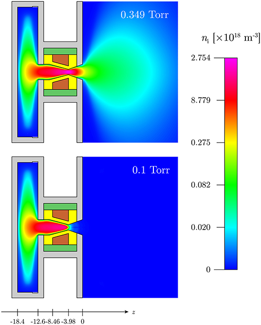
Figure 1. Schematic of the experimental system and CFD-plasma simulation set up showing major components and a 2D color map of the cycle average ion density ni for the 0.349 Torr outlet pressure reference simulation (top) and the 0.1 Torr outlet pressure DL simulation (bottom). The color scale is logarithmic with the yellow region of the spectrum representing 1/10 of the full scale. The propellant inlet is the notch in the corner of the plenum, and the flow direction is from left to right. The solid regions are: the discharge chamber wall (yellow, Al2O3), powered RF electrode (brown, Cu), insulation (dark green, Macor), and structure (gray, Al).
2.1.2. Numerical Method
The simulation method (mesh, volume conditions, boundary conditions, fluid dynamics, and kinetic treatment) is described in detail in Ho [30] and Ho et al. [31], and is summarized here. The CFD-plasma simulation mesh has 33, 667 cells with an optimum spatial resolution in the nozzle throat: the mesh density in the discharge chamber is 0.1 mm × 0.1 mm or under, varying because of the sloped nozzle walls; at the throat it is ~ 0.1 mm (along z) ×0.034 mm (0.75 mm radius divided by 22 cells along r). The input parameters for the CFD-plasma simulation correspond to an inlet boundary of 100SCCM of argon gas at 300 K outlet boundary conditions of 0.1 Torr and a backflow temperature of 100 K (bottom panel of Figure 1). The low backflow temperature ensures that the downstream region is an absolute thermal energy sink to approach “vacuum” expansion and is the lowest value that still produces a convergent solution. A slip boundary condition is used in this rarefied flow regime, with appropriate tangential momentum and thermal accommodation coefficient previously described and compared to experiments [31, 44–46].
The CFD-plasma simulation is solved in a transient manner in order to capture the time-dependent plasma dynamics within the RF cycle, with the powered electrode imposed with a 13.56 MHz RF waveform at 300 V peak. Two distinct solver time-steps are used, a time-step of Δτf = 1 s for fluid dynamics and a time-step of Δτp = 0.615 ns for plasma dynamics, equivalent to 1/120 of the RF period at 13.56 MHz (73.7 ns). These time-steps are used for solving their corresponding equations independently and do not have to be synchronized: the fluid iteration involves the flow, heat transfer and chemistry modules controlling parameters such as flow velocity and pressure. The plasma iteration involves the electric and plasma modules controlling parameters such as the electron number density, electron energy, and electric potential. Electron dynamics include particle and energy conservation, drift and diffusion transport, diffusivity and mobility, as well as ohmic, inductive, and collisionless stochastic sheath heating. Given the high collision frequency in this high pressure discharge, the electron energy distribution function is assumed to be a single temperature Maxwellian. Ion dynamics include drift and diffusion transport, diffusivity and mobility and inertia. The six plasma species Ar, Ar(4sm), Ar(4sr), Ar(4p), Ar+, and e- constitute a total of 29 volumetric reactions [30, 31, 46]. The plasma-facing solid surfaces (i.e., fluid-solid interfaces and the top left wall of the downstream region) are defined with surface chemical reactions that transform incident Ar(4sm), Ar(4sr), Ar(4p), and Ar+ species to neutral Ar with a sticking coefficient of unity. These surfaces are set to have a secondary electron emission coefficient of 0.1.
The final solution of the CFD-plasma simulation constitutes of the final 5 RF cycles (600 time-steps) after a convergence run lasting 500 RF cycles (60, 000 time-steps) and is representative of the periodic steady state at ~ 1 s after plasma ignition (experiments in cylindrical geometry have shown that the plasma reaches stability in less than ~ 1 s). The power injected in the discharge is computed to be 12.01 W. A second simulation which uses similar parameters except for an outlet boundary condition of 0.349 Torr and a backflow temperature of 300 K is used as a reference case (top panel of Figure 1) of a plasma where no double layer forms.
2.2. Pressure and Axial Ion Density
Figure 1 shows a 2D axisymmetric color map of the cycle average ion density ni over 5 RF cycles for the 0.349 Torr outlet pressure reference simulation (top panel) and the 0.1 Torr outlet pressure DL simulation (bottom panel). In this type of asymmetric discharge defined by the respective positioning and geometry of the grounded and RF electrodes, a negative self-bias forms on the surface of the dielectric radial walls in contact with the RF electrode: ion bombardment of the walls induces emission of secondary electrons primarily yielding a “gamma” power coupling mode [31, 44] and the self-bias and plasma generation are confined to the section of the discharge chamber wall in the convergent section of the nozzle. Figure 1 shows that similar maximum ion densities in the low 1018 m−3 range are obtained in the upstream plasma but a higher density exhaust plasma plume expands in the downstream region for the 0.349 Torr outlet pressure reference simulation. The 0.1 Torr outlet pressure simulation shows a very abrupt density decrease. This is further analyzed below.
The axial profile of the static pressure is shown in Figure 2. The static pressure (blue solid line) decreases from 6.38 Torr in the plenum (z = −18.4 mm) to 5.80 Torr at the position of maximum ion density (z = −5.58 mm, discussed below) to 3.37 Torr at the nozzle throat (z = −3.98 mm). The pressure at the nozzle exit (z = 0 mm) is 0.11 Torr, indicating close to ideal expansion into the 0.1 Torr ambient background pressure. The mean free path of ion-neutral charge exchange collisions at the entrance and exit of the nozzle (marked by the vertical dashed lines in Figure 2) is 2.4 m and 137 m respectively; at the throat (marked by the vertical dotted line) it is 4.5 m, i.e., orders of magnitude smaller than the throat diameter.
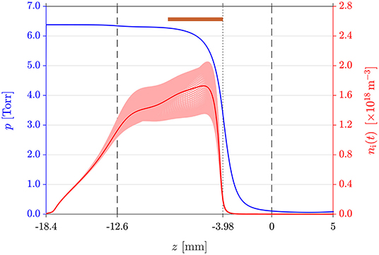
Figure 2. Static pressure p (blue solid line) and temporally varying ion density ni(t) (light red lines) and cycle average ni (red solid line) along the z-axis for the 0.1 Torr outlet pressure DL simulation. The brown bar at the top shows the axial location of the RF electrode around the nozzle. The entrance and exit of the nozzle are shown by the vertical dashed lines; the nozzle throat (i.e., end of the RF electrode) is indicated by the vertical dotted line.
The brown bar at the top of Figure 2 indicates the axial extent of the RF electrode. The ion density (red solid line) peaks near the downstream end of the RF electrode at z = −5.58 mm with , and the plasma extends upstream into the plenum. The temporal variation of ni during the RF cycle (light red lines) exhibits maximum variation of about ±20% at z = −5.58 mm. The ion density decreases to at the nozzle throat at z = −3.98 mm, and a much weaker plasma expands in the diverging part of the nozzle with at z = −1.3 mm (later defined as point C) and at z = 0 mm. The ionization fraction ni/n is less than ~ 2.5 × 10⁻⁵ throughout the plasma device and has a similar axial profile as that of ni; the electron to ion density ratio ne/ni is lower than 1 only in the plenum wall sheath, radial wall sheath, and in the DL structure. Electroneutrality is maintained everywhere else.
2.3. Plasma Potential
The plasma potential along the z-axis is plotted for both outlet pressure cases on Figure 3: the outlet boundary condition of 0.349 Torr (red line) shows a quasi-constant cycle average potential along the nozzle, i.e., there is no DL potential “structure.” Figure 3 plots the temporally varying Φp(t) (light blue lines) and cycle average Φp (solid blue line) plasma potential along the z-axis for the outlet boundary condition of 0.1 Torr. Φp(t) plotted at each of the 120 time-steps within the RF cycle reflects the electron dynamics of the capacitively coupled asymmetric discharge. The potential shapes across and just downstream of the nozzle throat are not dissimilar to the transformation of moving potential perturbations into a stationary potential DL as reported by Quon [6]. Here, during a large fraction of the RF cycle, the structure corresponds to a potential drop that accelerates ions across the nozzle throat into the divergent section of the nozzle. The cycle average Φp exhibits a steep potential drop (DL between point A and point B) near the nozzle throat, accompanied by a smaller amplitude potential barrier for ions (point B to point C) on the low-potential side of the DL in the divergent section of the nozzle. This type of structure with a clear negative potential dip (point B) has been reported for propagating DLs in computer simulations, in experimental systems, and in space plasmas, and is sometimes referred to as a triple or quadruple layer [2, 11, 20, 50]. Here point A is defined as the axial position where the local ion sound speed is reached [51] and point B is the axial position of minimum Φp. The electric DL (blue solid line between point A and point B in Figure 3) is stationary and constrained to the physical location corresponding to the nozzle throat. It is current-free since no direct current can flow from the “cathode” to ground.
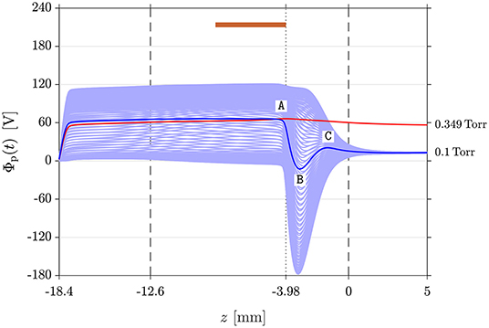
Figure 3. Temporally varying plasma potential Φp(t) (light blue lines) and cycle average Φp (blue solid line) along the z-axis for the 0.1 Torr outlet pressure DL simulation. Points A, B, and C correspond to the DL upper edge, lower edge, and the maximum potential of the tail barrier respectively. The red solid line represents Φp of the 0.349 Torr outlet pressure reference simulation (top panel in Figure 1). Vertical dashed and dotted lines are defined in Figure 2.
The cycle average plasma potential is Φp = 66.1 V at z = −5.58 mm where the ion density peaks. The abrupt potential drop between point A (Φp,A = 64.2 V at z = −4.28 mm) and point B (Φp,B = 12.7 V at z = −3.09 mm) yields a DC DL amplitude of ΔΦDL = 76.9 V. The thickness of the DL at Δz = 1.19 mm is a similar dimension to the throat diameter of 1.5 mm (Φp,throat = 51.8 V at z = −3.98 mm). The electron temperature kBTe is 2.25 eV at z = −5.58 mm, 2.64 eV at point A, and 5.16 eV at the nozzle throat respectively. DL strengths are usually estimated using the temperature of the coldest electron species entering the DL [52]: here using kBTe at point A yields ΔΦDL/(kBTe) ~ 29 which meets the definition of a strong current-free DL in literature [52]. Ion and electron axial transport across the nozzle throat is driven by the DL and its low-potential tail of amplitude 33.4 V existing between point B and point C (Φp,C = 20.7 V at z = −1.3 mm).
The total length of the potential structure between point A and point C is Δz = 2.98 mm. The Debye length λD at point A is 13 m, i.e., orders of magnitude smaller than the thickness of the potential structure of ~ 3 mm, the throat diameter of 1.5 mm, and the device dimensions. Using the plasma parameter values at point A yields a DL width of ~ 90 · λD which is typical of experimental and simulated DLs described in the literature [6, 21]. Detailed spatial characterization of DLs have been experimentally achieved in double plasma devices by reducing plasma densities (~ 1014 cm−3) to increase the Debye length [6, 52]. Here, fine spatial characterization of a DL of typical characteristic length and strength but for much higher densities (~ 1017 cm−3) is obtained via CFD-plasma modeling. The simulation is not limited to the DL itself but includes the complete plasma domain including all boundaries.
2.4. Electric Field and Ion Drift Velocity
To further study the ion dynamics across the DL, Figure 4 shows the temporally varying Ez(t) (light blue lines) and cycle average Ez (solid blue line) axial electric field as well as the temporally varying uz,i(t) (light red lines) and cycle average uz,i (solid red line) axial ion drift velocity. In the DL, a peak of is attained at z = −3.88 mm, slightly downstream of the nozzle throat (z = −3.98 mm).
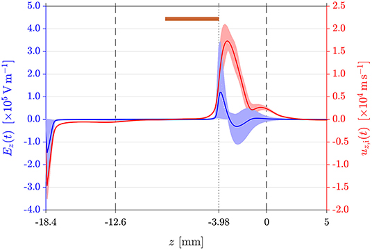
Figure 4. Temporally varying electric field Ez(t) (light blue lines) and ion drift velocity uz,i(t) (light red lines) along the z-axis for the 0.1 Torr outlet pressure DL simulation. The blue and red solid lines show the cycle average Ez and uz,i respectively. Vertical dashed and dotted lines are defined in Figure 2.
Ions are accelerated in the axial direction to a maximum drift velocity of at z = −3.29 mm, i.e., 0.6 mm downstream of the maximum Ez location. Using the kBTe = 11.4 eV at z = −3.29 mm yields , thus giving uz,i = 3.29·cs,i. Their kinetic energy is subsequently transferred to neutrals via ion-neutral charge exchange collisions. The pressure decreases from 4.26 Torr at point A, where the mean free path of ion-neutral charge exchange collisions for thermal ions at ~ 4 Torr is 3.8 m, to 1.06 Torr at point B (a factor of ~ 4). The ion density falls from 8.36 × 1017 cm−3 to 7.22 × 1015 cm−3 between point A and point B, i.e., a decrease by a factor of ~ 116. There are very few reports on the spatial characterization and occurrence of collisional DLs. Hollenstein et al. [7] have reported spatially resolved ion and electron temperature measurements in a current-driven stationary DL generated in a triple-plasma device in the presence of a low amplitude DC magnetic field (25 G), where the DL strength is of the order of ΔΦDL/(kBTe) ~ 5 with an upstream kBTe = 1.2 eV and a DL width in the 300 · λD to 500 · λD range. In their experiment, the effective collisional mean free path is 5 to 7 times smaller than the observed potential jump. The reported axial ion temperature profile obtained using a directional ion energy analyser shows a very similar peaked profile as that of uz,i in Figure 4. Turbulent collisions dominate the current-driven DL reported by Hollenstein et al. [7].
3. Discussion
In the present CFD-plasma model, the hot ions generated via acceleration through the DL thermalize with the neutrals via charge exchange collisions, as shown by the strong increase and subsequent decrease of uz,i just downstream of the nozzle throat (Figure 4). Similar ion collisional behavior has also been observed experimentally in the supersonic expanding plume of a cascade arc discharge, in which ion-neutral charge exchange collisions are responsible for enhancing recombination in the first few centimeters of the expansion (the axial potential profile was not provided for the device) [53]. Thermal heating of neutrals [46] is most significant in the region of maximum ion density (converging part of the nozzle), while the formation of the DL contributes to kinetic heating of neutrals in the throat region.
In an expanding nozzle, there is a cone of silence after the transonic point in the isentropic flow which essentially separates the upstream and downstream zones of flow, and the measured upstream flow is not affected by pressure changes in the downstream flow. The pressure gradient at the nozzle throat is a measure of the geometric expansion and induces significant changes in the plasma parameters as was shown for the resulting potential profile for the reference simulation run for a downstream outlet pressure of 0.349 Torr instead of 0.1 Torr (Figure 3). The DL is clearly not present when the downstream pressure is increased to 0.349 Torr (red line on Figure 3), resulting in a higher density exhaust plasma plume expanding into the downstream region (top panel in Figure 1). Although the present CFD-plasma simulation loses its validity for outlet pressures much lower than 0.1 Torr, the results suggest that similar nozzle results and DL formation would be obtained in vacuum [44]. For the 0.1 Torr outlet case, confinement of the plasma upstream of the nozzle throat minimizes electrical contact with the downstream grounded electrode and it is mostly the upstream plenum walls which form the ground electrode or “anode.” The DL acts as a boundary layer in an expanding plasma as predicted by Allen [16] but here it is current-free and self-consistently created by a single plasma generated upstream of the constriction. The potential drop forms spontaneously at the constriction to accelerate the ions and provide the necessary decrease in ion density for charge neutrality in the diverging part of the nozzle. The average ion transit time τi through the nozzle potential structure was calculated for the 0.1 Torr outlet pressure DL case by performing a fourth order Runge-Kutta analysis on the cycle average axial ion drift velocity to obtain the cycle average axial drift position of the ion as a function of time (Figure 5). The results have shown that τi between point A and point C is approximately 5 times the radiofrequency excitation period τRF = 73.7 ns, confirming that the ions respond to the cycle average plasma potential shown in Figure 3.
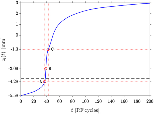
Figure 5. Runge-Kutta analysis of ion transit path across the DL potential structure (points A, B, and C defined on Figure 3) for the 0.1 Torr outlet pressure DL simulation. The vertical and horizontal dotted red lines are visual guides. The dashed horizontal line corresponds to the nozzle throat, i.e., end of the RF electrode (Figure 2).
The 0.349 Torr and 0.1 Torr (DL) outlet pressure cases are sufficiently choked to be comparable a 0 Torr vacuum case. The 0.1 Torr DL case should have mostly identical flow dynamics up to the nozzle and a bit beyond: the presence of the DL seems to not affect the fluid dynamics, but the cycle average axial neutral velocity (presented in Figure 13 of [44]) suggests the presence of some neutral pumping by ion-neutral charge exchange collisions downstream of the RF electrode. Still, these observations do not constitute absolute evidence of the phenomenon as the large fluid time-step size also affects the temporal variation of the axial neutral velocity.
Perkins and Sun [32] predicted the existence of current-free solutions with the assumption of Maxwellian electrons on both sides of the DL. Although the interpretation of electron temperature measurements is not easy and likely varies with the potential structure and is the object of on-going studies, both Sato [54] and Hollenstein et al. [7] have reported a localized increase of kBTe in collisionless and collisional DLs, respectively: from 2 eV to 11 eV in the former case and from to 1 eV to 8 eV in the latter. Presently, an increase from 2.25 eV at the position of maximum density (z = −5.58 mm) to 2.64 eV at point A and 11.8 eV at point B is observed. Perkins and Sun [32] acknowledged the lack of detail on the DL dynamics or on the high and low density plasma generation on either side, but extended their theoretical analysis to a negative surface charge density imposed by a grid within a plasma. In the present system, there is no immersed grid or electrode but there is a concentrated self-bias forming at the insulated RF electrode, and the plasma sheath along the discharge chamber wall in contact with the RF electrode merges to form a cone that becomes a current-free DL in the nozzle throat for a sufficiently low outlet pressure (i.e., 0.1 Torr).
Neutral gas heating can be directly applied to the optimization of electrothermal thrusters for space use and should play an increasing role in basic research on infrared emission spectroscopy applied to exoplanets such as “hot-Jupiters” [55]. In the context of thruster development, there is no electrode directly in contact with the plasma and no need for a neutralizer. The source of thrust is from heated neutrals, and the present geometry is a demonstration of optimization of both cold gas operation and plasma operation. The boundary DL controls charged particle transport between the converging and diverging parts of the nozzle. In the present DL case, the maximum gas temperature of about 825 K is obtained near the position of maximum axial ion density. Ion-neutral charge exchange collisions in the divergent section of the nozzle not only aid fast recombination and ensures a neutral plume, but may also impart axial momentum to a small population of neutrals and be beneficial for thrust performance. However, due to the low ionization fraction, this contribution and the thrust force from the remaining ions in the exhaust plume are expected to be very small relative to the main flow. In the present device the DL neutral heating mechanism is negligible compared to volumetric gas heating in the upstream section of the throat. Although not treated in the present simulation (which only reflects the first second after plasma ignition) neutral heating from the thermally lossy walls from ion bombardment for operation over 30–60 s will occur [56]. In much larger magnetized plasma nozzles (cavity diameter of about 15 cm) in which the operating pressure is of the order of a mTorr, the observed collisionless DL forming at the thruster exit plays a major role in ion heating/acceleration and thrust generation [35].
In the context of exoplanets research, there is increasing interest in ground-based laboratory spectroscopic data at very high temperatures in the infrared to update and upgrade the incomplete current databases used by theoreticians and modelers to retrieve the thermal structure and the composition of the atmosphere of hot exoplanets [55]: the high gas temperatures (up to 2, 500 K) make the calculation of these synthetic spectra currently extremely complicated with many unidentified features. Since a vibrational temperature of 4, 000 K for a 60 W nitrogen plasma has been previously experimentally obtained in a cylindrical version of the present plasma device [56], additional simulation work should help the future design of gas and plasma nozzles tailored for integration into High Enthalpy Source facilities [55] to produce high vibrational temperatures and low rotational temperatures jets: the low rotational temperatures obtained by jet expansion is of major importance for accessing high resolution “simplified” and controlled spectroscopic data [55]. It is envisaged that much greater gas flow rates needed by good optical/noise spectroscopic signal ratios compared to those used for the thruster application will be possible by considering laminar nozzles. Conditions less favorable to thruster operation at low input power when using molecular propellants (with a large fraction of the available power trapped in molecular vibrational states and never converted into propellant heating) are most favorable to spectroscopic studies for exoplanet research.
4. Conclusion
In summary, the class of current-free collisionless DLs generated by a single plasma source reported by Hairapetian [9] for two-temperature plasmas expanding in vacuum, by Charles [10] for low pressure expanding magnetized plasmas, and by Fruchtman [18] for space plasmas is presently extended to a current-free collisional DL forming in an unmagnetized converging-diverging plasma nozzle having a strong pressure gradient at the nozzle throat and a concentrated self-bias at a virtual insulated “cathode” to produce a single plasma in the converging part of the nozzle. The present simulations have been limited to a narrow range of external parameters; future studies will investigate the scaling of such DLs to initiate an experimental validation: although direct measurement of the localized ion acceleration would be challenging in small nozzles, experimental investigation of the plasma confinement mode may be possible using optical diagnostics. Recent demonstration of direct thrust measurement with increased sensitivity in the 0.1–1 mN range for a new prototype of such electrothermal thruster [57] suggests that additional experimental testing using this complimentary non-intrusive diagnostic can soon be envisaged.
Data Availability Statement
The raw data supporting the conclusions of this manuscript will be made available by the authors, without undue reservation, to any qualified researcher.
Author Contributions
TH performed all the simulation work (including preparation of all figures). CC prepared the manuscript with input from TH and RB. CC and RB supervised the research of Ph.D. student TH.
Conflict of Interest
The authors declare that the research was conducted in the absence of any commercial or financial relationships that could be construed as a potential conflict of interest.
Footnote
1. ^https://www.esi-group.com/software-solutions/virtual-environment/cfd-multiphysics/ace-suite/cfd-ace
References
1. Mozer FS, Carlson CW, Hudson MK, Torbert RB, Parady B, Yatteau J, et al. Observations of paired electrostatic shocks in the polar magnetosphere. Phys Rev Lett. (1977) 38:292–5. doi: 10.1103/PhysRevLett.38.292
2. Temerin M, Cerny K, Lotko W, Mozer FS. Observations of double layers and solitary waves in the auroral plasma. Phys Rev Lett. (1982) 48:1175–9. doi: 10.1103/PhysRevLett.48.1175
3. Carlqvist P. On the physics of relativistic double layers. Astrophys Space Sci. (1982) 87:21–39. doi: 10.1007/BF00648904
4. Coakley P, Hershkowitz N, Hubbard R, Joyce G. Experimental observations of strong double layers. Phys Rev Lett. (1978) 40:230–3. doi: 10.1103/PhysRevLett.40.230
5. Iizuka S, Michelsen P, Rasmussen JJ, Schrittwieser R, Hatakeyama R, Saeki K, et al. Dynamics of a potential barrier formed on the tail of a moving double layer in a collisionless plasma. Phys Rev Lett. (1982) 48:145–8. doi: 10.1103/PhysRevLett.48.145
6. Quon BH, Wong AY. Formation of potential double layers in plasmas. Phys Rev Lett. (1976) 37:1393–6. doi: 10.1103/PhysRevLett.37.1393
7. Hollenstein C, Guyot M, Weibel ES. Stationary potential jumps in a plasma. Phys Rev Lett. (1980) 45:2110–3. doi: 10.1103/PhysRevLett.45.2110
8. Sato N, Hatakeyama R, Iizuka S, Mieno T, Saeki K, Rasmussen JJ, et al. Ultrastrong stationary double layers in a nondischarge magnetoplasma. Phys Rev Lett. (1981) 46:1330–3. doi: 10.1103/PhysRevLett.46.1330
9. Hairapetian G, Stenzel RL. Observation of a stationary, current-free double layer in a plasma. Phys Rev Lett. (1990) 65:175–8. doi: 10.1103/PhysRevLett.65.175
10. Charles C, Boswell R. Current-free double-layer formation in a high-density helicon discharge. Appl Phys Lett. (2003) 82:1356–8. doi: 10.1063/1.1557319
11. Degroot JS, Barnes C, Walstead AE, Buneman O. Localized structures and anomalous dc resistivity. Phys Rev Lett. (1977) 38:1283–6. doi: 10.1103/PhysRevLett.38.1283
12. Sato T, Okuda H. Ion-acoustic double layers. Phys Rev Lett. (1980) 44:740–3. doi: 10.1103/PhysRevLett.44.740
13. Schrittwieser R. Double Layers and Other Nonlinear Potential Structures in Plasmas. Innsbruck: World Scientific (1992). p. 444–49.
14. Langmuir I. The interaction of electron and positive ion space charges in cathode sheaths. Phys Rev. (1929) 33:954–89. doi: 10.1103/PhysRev.33.954
15. Andrews JG, Allen JE. Theory of a double sheath between two plasmas. Proc R Soc A Math Phys Eng Sci. (1971) 320:459–72. doi: 10.1098/rspa.1971.0003
16. Allen JE. Some researches on double layers. Plasma Phys Control Fusion. (1985) 27:1343–57. doi: 10.1088/0741-3335/27/12A/002
17. Raadu MA. The physics of double layers and their role in astrophysics. Phys Rep. (1989) 178:25–97. doi: 10.1016/0370-1573(89)90109-9
18. Fruchtman A. Electric field in a double layer and the imparted momentum. Phys Rev Lett. (2006) 96:3–6. doi: 10.1103/PhysRevLett.96.065002
19. Lieberman MA, Charles C, Boswell RW. A theory for formation of a low pressure, current-free double layer. Phys Rev Lett. (2006) 97:045003. doi: 10.1103/PhysRevLett.97.045003
20. Hershkowitz N. Review of recent laboratory double layer experiments. Space Sci Rev. (1985) 41:351–91. doi: 10.1007/BF00190655
21. Charles C. A review of recent laboratory double layer experiments. Plasma Sources Sci Technol. (2007) 16:R1–25. doi: 10.1088/0963-0252/16/4/R01
22. Mozer FS, Cattell CA, Hudson MK, Lysak RL, Temerin M, Torbert RB. Satellite measurements and theories of low altitude auroral particle acceleration. Space Sci Rev. (1980) 27:155–213. doi: 10.1007/BF00212238
23. Jacobsen C, Carlqvist P. Solar flares caused by circuit interruptions. Icarus. (1964) 3:270–2. doi: 10.1016/0019-1035(64)90023-5
24. Boswell RW, Marsch E, Charles C. The current-free electric double layer in a coronal magnetic funnel. Astrophys J. (2006) 640:L199–202. doi: 10.1086/503155
25. Ohshima H, Makino K. Colloid and Interface Science in Pharmaceutical Research and Development. Oxford: Elsevier (2014). Available online at: https://www.elsevier.com/books/colloid-and-interface-science-in-pharmaceutical-research-and-development/ohshima/978-0-444-62614-1
26. Charles C. Plasmas for spacecraft propulsion. J Phys D Appl Phys. (2009) 42:163001. doi: 10.1088/0022-3727/42/16/163001
27. Takahashi K. Helicon-type radiofrequency plasma thrusters and magnetic plasma nozzles. Rev Modern Plasma Phys. (2019) 3:3. doi: 10.1007/s41614-019-0024-2
28. Charles C, Boswell RW, Takahashi K. Investigation of radiofrequency plasma sources for space travel. Plasma Phys Control Fusion. (2012) 54:124021. doi: 10.1088/0741-3335/54/12/124021
29. Charles C, Boswell RW. Measurement and modelling of a radiofrequency micro-thruster. Plasma Sources Sci Technol. (2012) 21:022002. doi: 10.1088/0963-0252/21/2/022002
30. Ho TS. Supersonic Constricted Plasma Flows. The Australian National University (2018). Available online at: https://hdl.handle.net/1885/148759
31. Ho TS, Charles C, Boswell R. Performance modelling of plasma microthruster nozzles in vacuum. J Appl Phys. (2018) 123:173301. doi: 10.1063/1.5012765
32. Perkins FW, Sun YC. Double layers without current. Phys Rev Lett. (1981) 46:115–8. doi: 10.1103/PhysRevLett.46.115
33. Sutherland O, Charles C, Plihon N, Boswell RW. Experimental evidence of a double layer in a large volume helicon reactor. Phys Rev Lett. (2005) 95:1–4. doi: 10.1103/PhysRevLett.95.205002
34. Sun X, Keesee AM, Biloiu C, Scime EE, Meige A, Charles C, et al. Observations of ion-beam formation in a current-free double layer. Phys Rev Lett. (2005) 95:1–4. doi: 10.1103/PhysRevLett.95.025004
35. Charles C, Boswell RW, Hawkins R. Oblique double layers: a comparison between terrestrial and auroral measurements. Phys Rev Lett. (2009) 103:28–31. doi: 10.1103/PhysRevLett.103.095001
36. Takahashi K, Charles C, Boswell R, Hatakeyama R. Erratum: Radial characterization of the electron energy distribution in a helicon source terminated by a double layer [Physics of Plasmas (2008) 15 (074505)]. Phys Plasmas. (2011) 18:74505. doi: 10.1063/1.2959137
37. Kolobov VI, Tsendin LD. Analytic model of the cathode region of a short glow discharge in light gases. Phys Rev A. (1992) 46:7837–52. doi: 10.1103/PhysRevA.46.7837
38. Song B, D'Angelo N, Merlino RL. On anode spots, double layers and plasma contactors. J Phys D. (1991) 24:1789–95. doi: 10.1088/0022-3727/24/10/012
39. Sirghi L, Ohef K, Popa G. Interactions between ionization waves and potential structure formed at a constriction of the dc He positive column. J Phys D. (1997) 30:2431–40. doi: 10.1088/0022-3727/30/17/009
40. Zobnin AV, Usachev AD, Petrov OF, Fortov VE. Two-dimensional positive column structure in a discharge tube with radius discontinuity. Phys Plasmas. (2014) 21:113503. doi: 10.1063/1.4901307
41. Kolobov VI, Metel AS. Glow discharges with electrostatic confinement of fast electrons. J Phys D. (2015) 48:233001. doi: 10.1088/0022-3727/48/23/233001
42. Embleus KG, Love B, Withersfoon AE. The striated positive column. J Electron Control. (1956) 1:559–60. doi: 10.1080/00207215608961457
43. Arslanbekov RR, Kolobov VI. Advances in simulations of moving striations in DC discharges of noble gases. Phys Plasmas. (2019) 26:104501. doi: 10.1063/1.5121846
44. Ho TS, Charles C, Boswell R. Redefinition of the self-bias voltage in a dielectrically shielded thin sheath RF discharge. J Appl Phys. (2018) 123:193301. doi: 10.1063/1.5023076
45. Ho TS, Charles C, Boswell RW. A comprehensive cold gas performance study of the pocket rocket radiofrequency electrothermal microthruster. Front Phys. (2017) 4:55. doi: 10.3389/fphy.2016.00055
46. Ho TS, Charles C, Boswell R. Neutral gas heating and ion transport in a constricted plasma flow. Phys Plasmas. (2017) 24:084501. doi: 10.1063/1.4996014
48. Kolobov VI. Fokker Planck modeling of electron kinetics in plasmas and semiconductors. Comput Mater Sci. (2003) 28:302–20. doi: 10.1016/S0927-0256(03)00115-0
49. Kolobov VI, Arslanbekov RR, Bogdanov EA, Eliseev S, Kudryavtsev AA. Comparison of computational tools for simulations of glow and corona discharges. In: 31st International Conference on Ionised Gases. Granada (2013).
50. Bennet A, Charles C, Boswell RW. Field-aligned Boltzmann electric triple layer in a low-pressure expanding plasma. Plasma Sources Sci Technol. (2019) 28:06LT01. doi: 10.1088/1361-6595/ab20a5
51. Stangeby PC, Allen JE. Plasma boundary as a mach surface. J Phys A Proc Phys Soc Gen. (1970) 3:304–8. doi: 10.1088/0305-4470/3/3/017
52. Coakley P, Hershkowitz N. Laboratory double layers. Phys Fluids. (1979) 22:1171. doi: 10.1063/1.862719
53. Meulenbroeks RFG, Schram DC, Jaegers LJM, van de Sanden MCM. Rayleigh scattering as a means of molecular concentration. Phys Rev Lett. (1992) 69:1379–82. doi: 10.1103/PhysRevLett.69.1379
54. Sato N. Double Layers and Other Nonlinear Potential Structures in Plasmas. Innsbruck: World Scientific (1992). p. 273–78.
55. Louviot M, Suas-David N, Boudon V, Georges R, Rey M, Kassi S. Strong thermal nonequilibrium in hypersonic CO and CH 4 probed by CRDS. J Chem Phys. (2015) 142:214305. doi: 10.1063/1.4921893
56. Greig A, Charles C, Paulin N, Boswell RW. Volume and surface propellant heating in an electrothermal radio-frequency plasma micro-thruster. Appl Phys Lett. (2014) 105:054102. doi: 10.1063/1.4892656
Keywords: plasma simulation, plasma nozzle, thruster, double layer, ion acceleration
Citation: Ho TS, Charles C and Boswell RW (2019) Current-Free Electric Double Layer in a Small Collisional Plasma Thruster Nozzle Simulation. Front. Phys. 7:200. doi: 10.3389/fphy.2019.00200
Received: 25 August 2019; Accepted: 11 November 2019;
Published: 27 November 2019.
Edited by:
Gianpiero Colonna, Italian National Research Council (CNR), ItalyReviewed by:
Andrea Cristofolini, University of Bologna, ItalyVladimir I. Kolobov, CFD Research Corporation, United States
Copyright © 2019 Ho, Charles and Boswell. This is an open-access article distributed under the terms of the Creative Commons Attribution License (CC BY). The use, distribution or reproduction in other forums is permitted, provided the original author(s) and the copyright owner(s) are credited and that the original publication in this journal is cited, in accordance with accepted academic practice. No use, distribution or reproduction is permitted which does not comply with these terms.
*Correspondence: Christine Charles, christine.charles@anu.edu.au