Physical Characteristics of Section Coal and Rock Pillars Under Roof Shock Disturbances From Goaf
 Ronghua Su
 Hongshuang Shen
- School of Mechanics and Engineering, Liaoning Technical University, Fuxin, China
The stability of a rock strata structure is closely related to its response physical characteristics under external shock disturbance. The roof shock disturbance from goaf is usually one of the important factors that cause coal and rock pillar instability. It is necessary to study the dynamic physical characteristics of coal and rock pillars under roof shock disturbance from goaf. The dynamic structural system model of elastic-plastic finite element was established for the formation of surrounding rock and coal pillars in a deep stope. The response physical characteristics of coal pillars with different widths were analyzed under the roof shock disturbance intensity and frequency from goaf. The natural vibration characteristics of the stope model were calculated and the first 10-order natural frequencies were extracted. The calculations indicated that the vertical displacement and the plastic zone occupation ratio of the coal pillar increased with the increase of the shock disturbance intensity, decreased with the increase of the shock disturbance frequency, and decreased with the increase of the coal pillar width. The influence of the vertical deformation and the plastic zone occupation ratio of the coal pillar under shock disturbance frequency was more obvious compared with that of the shock disturbance intensity, especially at low frequency. The closer the shock disturbance frequency was to the natural frequency of the model, the larger the plastic zone of the coal pillars was, with the bearing capacity of the coal pillar decreasing significantly. It is significant that more attention should be paid to monitoring the frequency of roof shock disturbance signal when designing coal pillars width in the coal mine.
Introduction
Owing to the layout of the mining operation for underground coal mining, a large number of coal and rock pillars are needed [1–4]. The coal and rock pillars have many different functions, including protecting the tunnels, isolating goafs, and avoiding surface subsidence [5–9]. The stability of coal and rock pillars will directly affect the safe production of mines and the safety of surface buildings. The stress conditions of coal and rock pillars are complex [10]. These pillars are subjected to various kinds of shock disturbances caused by mining operations, such as blast vibrations, periodic pressure disturbances, and mine earthquakes, while being subjected to gravity loads [11–14]. The periodic fault–slip burst of a roof is a common phenomenon triggered by a shock disturbance during cave mining; this phenomenon has the characteristics of a short action time and a great shock disturbance force [15]. Shock disturbances have a great influence on the stability of coal pillars. A strong shock disturbance is one of the main factors that induce dynamic disasters of deep coal mine stopes. The determination of the section coal pillars width in a high-strength mine with a fully mechanized top-coal caving working face should consider many factors, such as repeated and intensive mining, basic roof fractures, large tunnel sections, and other shock disturbance factors [16, 17]. The rational design and the stability analysis of the coal and rock pillar size have caused a great concern in the field of mining at home and abroad and have become important research topics [18–24]. An understanding of the mechanical response characteristics of coal and rock pillars under complex loading conditions is expected and is the premise of the abovementioned analysis.
External shock disturbance must be taken into account when selecting the section coal and rock pillar widths. Thus, it has been very important to study the stability of section coal and rock pillars and determine the width of section coal and rock pillars. A mechanical model of section coal pillars with different widths during working face extraction was established by fast Lagrangian analysis of continua in three dimensions [25]. Comparing the differences in the distribution laws of the stress and deformation and plastic zones in the surrounding rock, a reasonable width of the section coal pillars was obtained. Generally, the reasonable width of a coal and rock pillar under dynamic simulation was much larger than that under static simulation [26]. The stress state of coal bodies subjected to the effect of roof strata was investigated, and the shock risk of the roof fracture vibration on coal was studied by numerical simulation [27]. The results showed that the shock risk of the coal body increases during roof shock disturbance. Crack initiation, development, and propagation in the coal were one cause of coal body instability [28]. The deformation of coal and rock pillars during excavation could be determined by on-site monitoring, and better monitoring results were obtained by using a 3D laser scanner [29]. To effectively reduce the shock disturbance on coal and rock pillars due to the dynamic pressure of mining, the stability of coal pillars in a bilateral goaf was analyzed by theoretical analyses and numerical simulations, and the stress distribution characteristics of section coal pillars were obtained [30]. Previous researches have also studied the microcrack development, structural damage, and energy transformation of coal and rock mass to the failure rules of coal and rock mass and revealed the mechanism of coal and rock dynamic disasters [31–33]. Acoustic emission technique and moment tensor analysis were used to evaluate the temporal–spatial evolution and damage of micro-cracks of schist [34]. The study of energy conversion and failure mechanism of coal mass under repeated loads was beneficial to the risk assessment of dynamic disasters [35]. It is necessary to reveal the principle of the dynamic shock disturbance effect of the roof under high-strength mining. The conditions, mechanism, and influencing factors that induced the dynamic load shock effect of the roof in high-strength mining stopes were investigated [36]. The study of the dynamic physical characteristics of coal and rock structure under shock disturbance intensity is a hot topic. The stability of the section coal and rock pillars also depends on whether the design of the coal and rock pillars is in line with the actual situation and whether the construction is in place. To investigate the reasonable size of coal and rock pillars, field monitoring and analyses [37, 38], similar simulation experiment analyses [39, 40], numerical simulations [22, 41], and other means have been applied to study the mechanism of section coal and rock pillar-induced dynamic disasters.
Roof shock disturbance from goaf, which affects mining safety, is one of the important factors to study on the dynamic physical characteristics of section coal and rock pillars. A dynamic structural system model of elastic-plastic finite element was established for the formation of surrounding rock and coal pillars in a deep stope. The physical characteristics of section coal and rock pillars in the model were investigated mainly by varying the shock disturbance frequencies and the intensities in the research. The variation characteristics of the vertical deformation and plastic zone of different section coal pillar widths, under a combination of different shock disturbance intensities and frequencies, were discussed. The vibration characteristics of the stope model were analyzed. The relationship between the physical characteristics of coal pillars under roof shock disturbance frequency and the natural vibration characteristics of the stope was discussed and analyzed. This study could provide a theoretical reference for the rational design and stability analysis of section coal and rock pillars used in deep coal mine stopes.
Basic Assumptions and Model Establishment
Engineering Background and Basic Assumptions
The coal field of the underground coal mine is 850 m in depth. It belongs to the North China-type carboniferous Permian coal-bearing strata, which is located in the north margin of the syncline and is a monoclinal structure. The average thickness of the coal seam is 4 m, and the coal seam is a nearly horizontal structure. The dip angle of the maximum principal stress in the in situ stress field of the mining area is close to the horizontal direction. The in situ stress in the mining area is mainly horizontal tectonic stress. The bearing of the maximum principal stress is north by west. The roof is composed mostly of mudstone and sandy mudstone, and the floor is composed mostly of dark gray sandy mudstones. Using the method of longwall mining, the full height is immediately mined. According to the actual situation of the field, the basic hypothesis of the model is as follows: the rock stratum is regarded as a horizontal rock layer. The section coal and rock pillars (section coal pillar; hereafter sometimes referred to as the pillar) and the surrounding rock strata in the deep coal mine stope (hereafter sometimes referred to as the stope) are established by an elastoplastic model to analysis. The section coal and rock pillars, direct roof rock, and direct bottom rock of the coal seams are treated as elastic-plastic bodies, while the other layers adopt an elastic model. The Drucker–Prager (D–P) yield criterion is satisfied. The yield condition of the D–P criterion is:
where I1 is the first invariant of the stress tensor, J2 is the second invariant of the strain tensor, , , c is the cohesion of the material, and ϕ is the friction angle.
A schematic diagram of the section coal pillar arrangement in the profile of a fully mechanized mining face is shown in Figure 1. It is the profile along the strike of the vertical working face. The changes of vertical deformation and plastic zone (the region where deformation occurs under roof shock disturbance) of section coal and rock pillars are analyzed by adopting the plane strain model.
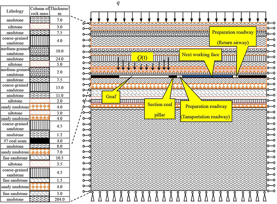
Figure 1. Schematic diagram of the section coal pillar arrangement in profile of fully mechanized mining face.
Figure 1 presents the schematic diagram of the section coal pillar arrangement. The figure shows the stratal relationships.
The width of the section coal pillars (represented by symbol B) of the stope model can be designed with different values on the working face. B refers to the solid section coal pillar width, q is the uniformly distributed vertical stress, and Q(t) is the shock disturbance. The physical and the mechanical parameters of the coal and rock are obtained through laboratory experiments, and they are shown in Table 1. The computed strength of coal is equivalent strength, which considers the supporting conditions.
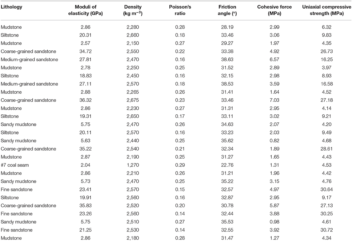
Table 1. The physical and the mechanical parameters of coal and rock.
Finite Element Model
Adopting the ANSYS software, the deep coal mine stope model containing section coal and rock pillars is established, which is 628 m in length and 364.7 m in height. The Plane 82 unit (plane strain mode) is adopted. There are 27 layers of coal and rock, the thickness of each coal and rock stratum is different, and the coal is mined from the 18th layer. In this layer, the goaf is 200 m in length, the width of the section coal pillars is set as a variable quantity, and the tunnel is 4 m in length. Using the mapping grid, the key parts are processed by encrypted grids. For example, when 24 m of section coal pillars is left, 7,504 units and 7,684 nodes are divided into finite element models. To eliminate the influence of boundary effects, a 200-m boundary remains at the left and at the right ends of the model. The constraint conditions include a horizontal displacement constraint on the left and the right boundaries and a vertical displacement constraint on the lower boundary. The stress of the overlying strata, with a thickness of 750 m, is simplified as a uniformly distributed load on the top of the model. The finite element model of the deep stope with section coal pillars is shown in Figure 2.
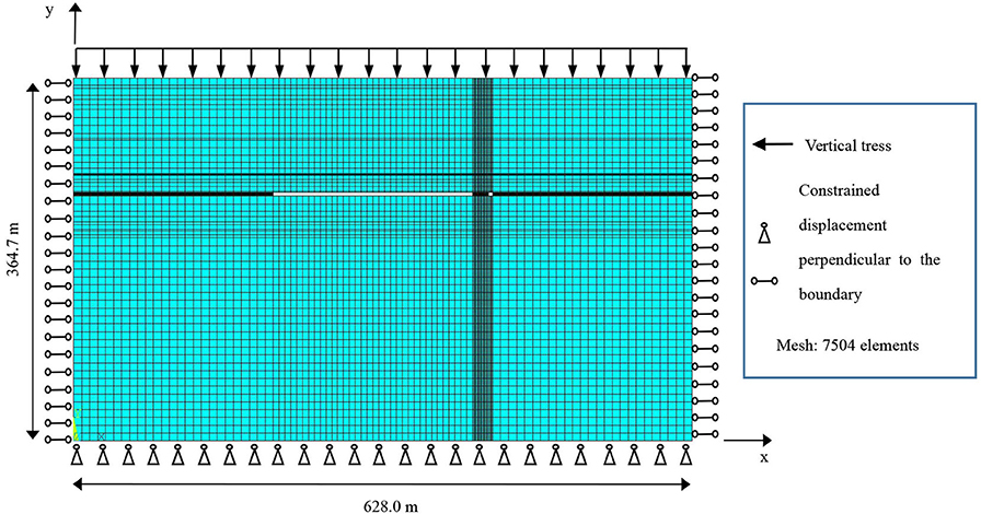
Figure 2. Finite element model of the deep stope with section coal pillars.
According to the Ginnick hypothesis named after the Soviet scholar, the stress boundary conditions are as follows:
where q is the uniformly distributed vertical stress, γ is the average bulk density of the rock mass, which is set as 24.96 kN/m3, and H is the thickness of the overlying strata of the coal seam.
In the finite element model, the thickness of the overlying strata of the coal seam is 750 m. Using formula (2), the vertical stress is calculated to be 18.75 MPa, i.e., q = 18.75 MPa.
The shock disturbance from the overlying strata has a significant effect on the lower rock layer or coal seam, such as the sudden breaking of the main roofs, which is much more than the effect of gravity. Q(t) is the shock disturbance produced by the main roof fracture. The shock disturbance mainly propagates in the lower rock by the form of stress waves [42]. Almost all the elastic waves are superimposed by several simple harmonic waves with different amplitudes and frequencies. It is assumed that the elastic wave from the goaf roof satisfies the following relationship:
where Q(t) is the shock disturbance, F is the amplitude of the shock disturbance intensity, f is the shock disturbance frequency, and t is time; t0 = 1/ω, ω is the dynamic load frequency and t0 is the dynamic load period.
According to the actual geological conditions and a large number of field monitoring datapoints, F is selected as 20, 30, or 40 MPa, and f is selected as 5, 8, 10, 25, or 40 Hz in this research. The physical characteristics of section coal pillars are analyzed.
Response Characteristics of Coal Pillars Under Shock Disturbance
Mechanical Analysis After Working Face Excavation
By simulating the coal mining process, the physical characteristics of section coal pillars are analyzed after excavation, the widths of which are B1 = 16 m, B2 = 24 m, B3 = 30 m, or B4 = 40 m. According to these four coal pillar widths, the vertical displacement and the vertical stress are obtained. Figure 3A shows the displacement contour map of the stope, where the 16-m section coal pillar is located, and the local enlarged displacement contour map of the section coal pillar. Figure 3B shows the displacement contour map of the stope, where the 24-m section coal pillar is located, and the local enlarged displacement contour map of the coal pillar. The displacement of the section coal pillar is asymmetrically distributed. The displacement of the left side of the section coal pillar next to the goaf is larger than that of the right side next to the tunnel. The maximum displacement occurs at the upper of the section coal pillar next to the goaf. With the increase of the section coal pillar width, the change tendency of the displacement on both sides of the section coal pillar decreases. The results show that the wider the section coal pillar is, the safer the section coal pillar is.
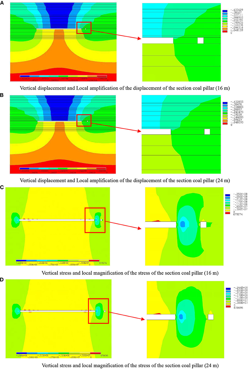
Figure 3. Vertical displacement contour maps and vertical stress contour maps of the deep stope with 16 and 24 m section coal pillar width. (A) Vertical displacement and Local amplification of the displacement of the section coal pillar (16 m). (B) Vertical displacement and Local amplification of the displacement of the section coal pillar (24 m). (C) Vertical stress and local magnification of the stress of the section coal pillar (16 m). (D) Vertical stress and local magnification of the stress of the section coal pillar (24 m).
Figures 3C,D show the contour maps of the potential stress distribution in the stope. Figure 3C shows the stress contour map of the stope, where the 16-m section coal pillar is located, and the local enlarged stress contour map of the section coal pillar. Figure 3D shows the stress contour map of the stope, where the 24-m section coal pillar is located, and the local enlarged stress contour map of the coal pillar. The maximum vertical stress of the section coal pillar decreases with the increase of the section coal pillar width. When the section coal pillar width is >24 m, the stress distribution law of the section coal pillar has no obvious change with the increase of the section coal pillar width. The stress concentration of the section coal pillar decreases gradually with the increase of the coal pillar widths.
Vertical Deformation Characteristics of Pillars Under Shock Disturbance
In order to get the vertical deformation characteristics of pillars under roof shock disturbance, the shock disturbance from goaf is set to F1 = 20 MPa, with f = 25 Hz and t = 40 ms. The transient nonlinear dynamic response is calculated, the analysis pillar widths selected of which are B1 = 16 m, B2 = 24 m, B3 = 30 m, or B4 = 40 m, respectively.
The displacement observation points (represented by the symbol wi) are arranged in pairs at the top and the bottom of the pillar at 1-m intervals, that is, B1 = 16 m, i = 16; B2 = 24 m, i = 24; B3 = 30 m, i = 30; and B4 = 40 m, i = 40. The numbering of the displacement observation points of the pillar starts from the side of the goaf. The layout diagram of the measuring points is shown in Figure 4. The vertical displacement is represented by the symbol Uy. The vertical displacement of the different width pillars are monitored by observation points, and the deformation between each pair of observation points is calculated by:
where Uyi is the vertical displacement of the i-th pair of observation points, Uyi, up is the vertical displacement of the i-th observation point at the top of the coal pillar, and Uyi, bottomis the vertical displacement of the i-th observation point at the bottom of the coal pillar.
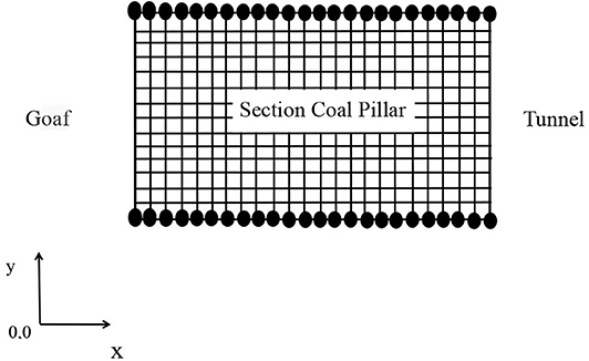
Figure 4. Layout diagram of the displacement observation points of the 24 m section coal pillar.
By using formula (2), the vertical deformation of coal pillars is obtained, and the deformation curves of the different widths coal pillar are shown in Figure 5. On the one hand, there is no effect of the shock disturbance intensity on the section coal pillar. On the other hand, the effect of the shock disturbance intensity and the frequency are considered. Clearly, the trends of the vertical deformation curves of the different widths coal pillar are similar, and the vertical deformation Uyi is related to coal pillar widths B. By comparison, the vertical deformation Uyi on the left side of the section coal pillar obviously increases under shock disturbance, and the vertical deformation Uyi on the right side of the section coal pillar changes slightly. The larger the section coal pillar width is, the smaller the deformation of the right side of the section coal pillar is. It is revealed that the deformation of the section coal pillar decreases with the increase of coal pillar widths under shock disturbance.
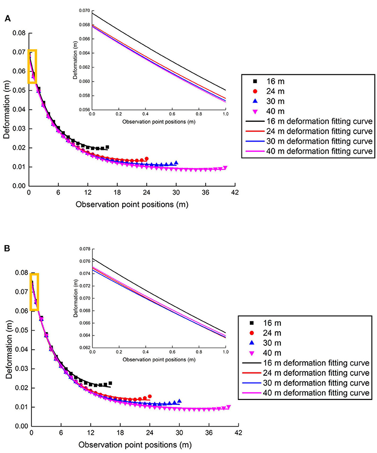
Figure 5. Vertical deformation curves of the observation points of section coal pillars with different widths. (A) Without shock. (B) With shock.
Development Characteristics of the Plastic Zone in the Coal Pillar
The plastic strain distribution (plastic strain is represented by the symbolεp) in section coal pillars with different widths are analyzed under the following shock disturbances: F1 = 20 MPa, f = 25 Hz, and t = 40 ms. Figure 6 shows the distribution cloud charts of εp, considering the 24-m section coal pillar. As shown in Figure 6A, the shock disturbance is not considered, and in Figure 6B, the model considers the shock disturbance conditions of F1 = 20 MPa, f = 25 Hz, and t = 40 ms. It was found that εp is related to B, and εp on the left of the section coal pillar, near the goaf, is more sensitively affected by the shock disturbance. Compared with the strain cloud charts of the coal pillar under shock disturbance and without shock disturbance, it shows that shock disturbance causes a sudden increase of strain on the top of the coal pillar and an obvious increase of the plastic zone.
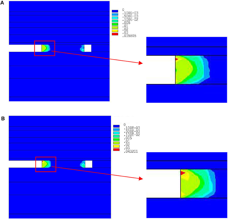
Figure 6. Plastic strain distribution cloud charts of the 24 m section coal pillar. (A) Without shock. (B) With shock.
The percentage of plastic zone in the coal pillar is represented by the symbol ΔR (herein referred to as the plastic zone occupation ratio), which satisfies the following relation:
where R is the plastic zone area in the coal pillar, A is the area of the coal pillar, ΔR is a function of F, f , and B in this research, which is ΔR=ΔR(F, f, B).
Table 2 displays the data of ΔR in coal pillars under shock disturbance or without shock disturbance. The plastic zone occupation ratio of the coal pillar under shock disturbance intensity F is represented by the symbol ΔRS, and the plastic zone occupation ratio of the coal pillar under without F is represented by the symbol ΔRN. Clearly, ΔRS is higher than ΔRN of the section coal pillars, and ΔRS> ΔRN is true for all section coal pillar widths. Furthermore, ΔR is related to B. Usually, ΔR is used to evaluate the damage of the coal pillars.
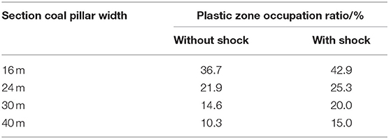
Table 2. Plastic zone occupation ratio with different section coal pillar widths.
Physical Characteristics of Pillars Under Different Shock Disturbance Intensities
Vertical Deformation of Section Coal Pillars Under Different Shock Disturbance Intensities
The model is disturbed by different shock disturbance intensities. The shock disturbance intensities are F1 = 20 MPa, F2 = 30 MPa, or F3 = 40 MPa, where the shock disturbance frequency is f = 25 Hz and the coal pillar widths are B1 = 16 m, B2 = 24 m, B3 = 30 m, or B4 = 40 m. The vertical deformation Uy(F, f, B) (F ∈ [F1, F2, F3], and B ∈ [B1, B2, B3, B4]) of coal pillars is obtained. Figure 7 shows the vertical deformation curves varying with the observation points position wi in the coal pillar. In Figure 7, the vertical deformation increases with the shock disturbance intensity, which creates a greater deformation at the goaf side (the left side of the coal pillar). On the left side of the coal pillar, the vertical deformation Uy(F, f, B)|F=F3 of the observation point under shock disturbance intensity F3 is obviously greater than that of Uy(F, f, B)|F=F1 under shock disturbance intensity F2. With the increase of the coal pillar width, the middle position of the coal pillar is formed, the deformation invariable area (where no plastic strain occurs in the section coal pillar), and the external shock disturbance intensity is not obviously affected on the deformation of coal pillar. The deformation of both sides of the coal pillar is changed under the shock disturbance intensity, of which there is always
at f = 25 Hz with the same coal pillar width.
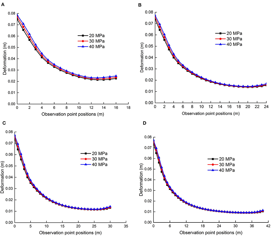
Figure 7. Vertical displacement curves of the coal pillar varying with different pillar widths and shock disturbance intensities. (A) Vertical displacement curves of the 16 m section coal pillar. (B) Vertical displacement curves of the 24 m section coal pillar. (C) Vertical displacement curves of the 30 m section coal pillar. (D) Vertical displacement curves of the 40 m section coal pillar.
Plastic Deformation Characteristics of Pillars Under Different Shock Disturbance Intensities
The maximum plastic strain εpmax of the section coal pillars under different shock disturbance intensities are shown in Table 3, considering that F1 = 20 MPa, F2 = 30 MPa, or F3 = 40 MPa and f = 25 Hz, that is, F ∈ [F1, F2, F3] and B ∈ [B1, B2, B3, B4]. The maximum plastic strain εpmax(F, f, B) of the coal pillar increases with the increase of shock disturbance intensity F, when the coal pillar width is fixed, that is:
under shock disturbance frequency f = 25 Hz.
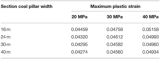
Table 3. Maximum plastic strain of section coal pillars varying with different widths.
The more serious the plastic deformation of the coal pillar is, the more serious the damage of the coal pillar is.
The plastic zone occupation ratio ΔR(F, f, B) of the coal pillar is calculated under different shock disturbance intensities, where, and f = 25 Hz. The corresponding histogram of the plastic zone occupation ratio is shown in Figure 8. The plastic zone occupation ratio ΔR(F, f, B) of the coal pillar increases and the damage probability of the coal pillar increases with the increase of shock disturbance intensity under the same shock disturbance frequency, that is,
while the coal pillar width is fixed.
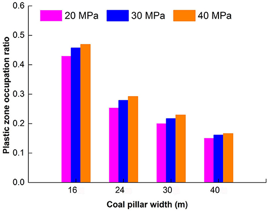
Figure 8. Plastic zone occupation ratio chart of section coal pillars varying with different widths and shock disturbance intensities.
The plastic zone occupation ratio ΔR(F, f, B) of the coal pillar decreases with the increase of coal pillar widths when the shock disturbance intensity of the coal pillar is fixed; thus:
The dynamic physical characteristics of the section coal pillars under the shock disturbance intensity do not change significantly when the coal pillar width is >24 m.
Physical Characteristics of Pillars Under Different Shock Disturbance Frequencies
Vertical Deformation of Pillars Under Various Shock Disturbance Frequencies
The vertical deformation of the section coal pillars is obtained under different shock disturbance frequencies. The shock disturbance frequency is f 1 = 5 Hz, f 2 = 8 Hz, f 3 = 10 Hz, f 4 = 25 Hz, or f 5 = 40 Hz applied to the model, while the shock disturbance intensity is F1 = 20 MPa, and the coal pillar width is set to B1 = 16 m, B2 = 24 m, B3 = 30 m, or B4 = 40 m, that is, f ∈ [f1, f2, f3, f4, f5], B ∈ [B1, B2, B3, B4]. The vertical deformation Uy(F, f, B) of section coal pillars changed with displacement observation points wi, as shown in Figure 9. Figure 9 shows that the larger the shock disturbance frequency is, the smaller the vertical deformation Uy(F, f, B), while the shock disturbance intensity is constant. The change of the vertical deformation Uy(F, f, B) of the section coal pillars is more significant under shock disturbance frequency compared with that of shock disturbance intensity. The low shock disturbance frequency causes a large vertical deformation Uy(F, f, B) to the coal pillar. Specifically, the deformation Uy(F, f, B) of both sides of the 16-m section coal pillar is more obvious under a condition of f = 5 Hz shock disturbance, where the Uy(F, f, B) of the coal pillar is obviously affected by the shock disturbance frequency f .
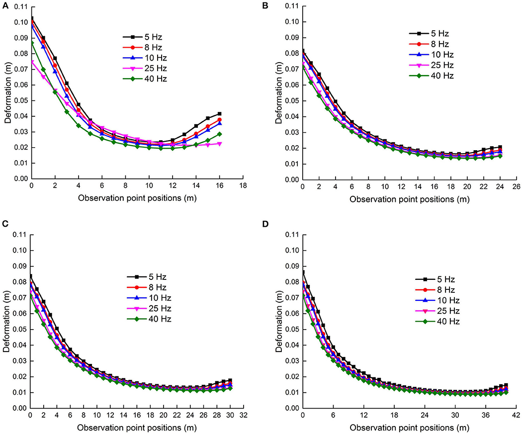
Figure 9. Vertical displacement curves of the section coal pillar varying with different widths and shock disturbance frequencies. (A) Vertical displacement curves of the 16 m section coal pillar. (B) Vertical displacement curves of the 24 m section coal pillar. (C) Vertical displacement curves of the 30 m section coal pillar. (D) Vertical displacement curves of the 40 m section coal pillar.
Plastic Deformation Characteristics of Section Coal Pillars Under Various Shock Disturbance Frequencies
Figure 10 shows a histogram of the plastic zone occupation ratio ΔR(F, f, B) in the section coal pillars with different coal pillar widths, wheref ∈ [f1, f2, f3, f4, f5], B ∈ [B1, B2, B3, B4], and F is a constant.
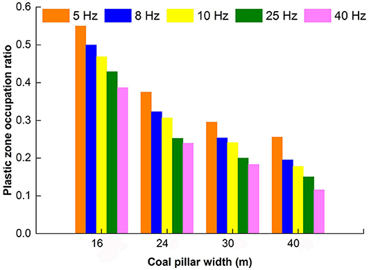
Figure 10. Plastic zone proportion ratio chart of section coal pillars varying with different widths and shock disturbance frequencies.
It can be seen from Figure 10 that the plastic zone occupation ratio ΔR(F, f, B) decreases with an increase in the shock disturbance frequency f for the same shock disturbance intensity F, while the coal pillar width is a constant. When the shock disturbance frequency is f = 5 Hz, the plastic zone occupation ratio of B1 = 16 m accounts for more than 50%, that is, ΔR(F, f, B)|f=f1, B=B1 > 50.0%, and there is a potential safety hazard, which is if the coal pillar loses its carrying capacity. When the width of the coal pillar is B2 = 24 m, ΔR(F, f, B)|f=f1, B=B2 = 39.0%. When the coal pillar width is B3 = 30 m or B4 = 40 m and the plastic zone occupation ratio ΔR(F, f, B)|f=f1, B=B3 or ΔR(F, f, B)|f=f1, B= B4 is < 35.0%, then the coal pillar has a better bearing capacity. It turns out that the smaller the frequency f is, the larger the plastic zone occupation ratio ΔR of the coal pillar is.
Under different shock disturbance intensities and frequencies, in the case of the same section coal pillar width, it turns out that the plastic zone occupation ratio increases with increasing shock disturbance intensity, that is:
and decreases with the increase of the shock disturbance frequency, that is:
The change of the dynamic physical characteristics of coal pillars is more obvious under shock disturbance frequency than that of shock disturbance intensity. Especially the plastic zone proportion ratio of the section coal pillars is changed obviously under shock disturbance frequency. When the shock disturbance frequency is
there are always
regardless of the coal pillar width.
Natural Vibration Characteristics of the Stope
The natural vibration characteristics of the deep coal mine stope are simulated, and the natural vibration frequencies and modal shapes are obtained. The natural frequencies of the stope model with different section coal pillars widths are listed in Table 4. The first three-order modes of the stope with a 16-m section coal pillar and a 24-m section coal pillar are shown in Figure 11.
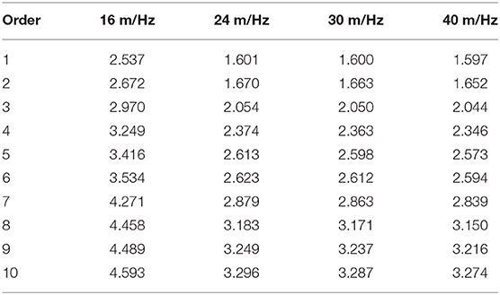
Table 4. Natural frequency of the stope of section coal pillars varying with different widths.
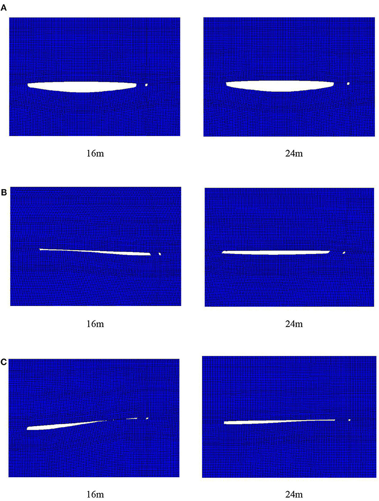
Figure 11. Cloud charts of the stope vibration mode of the 16 m section coal pillar and the 24 m section coal pillar. (A) First-order mode. (B) Second-order mode. (C) Third-order mode.
In Table 4, the natural vibration frequencies of the first 10-order modes of the stope model are <5 Hz. The natural vibration frequencies decrease with the increase of the section coal pillar width, the magnitude of the decrease of which varies.
The above analysis reveals that the effect of the shock disturbance frequency is more sensitive than that of the shock disturbance intensity under the given calculation conditions. According to the analysis of the natural vibration characteristics of the coal pillars of the stope, the deformation of the roof or the floor in the goaf is remarkable, and the deformation of the adjacent sides of the coal pillar and goaf is also significant. The first 10 natural frequencies of the stope are all low frequency. If the shock disturbance frequency is lower than 5 Hz, the development of the plastic zone of the section coal pillars is inevitably accelerated. The mechanical response of the section coal pillars under a shock disturbance is closely related to the natural vibration characteristics of the stope with pillars.
The 24-m coal pillar was used to the mine. The deformation of the coal pillar had been monitored. The results were consistent with the numerical calculation results. The model and the results obtained are credible and meaningful. In conclusion, the 24-m section coal pillar retained can meet the design requirements on the working face of the deep coal mine stope with section coal pillars.
Conclusion and Discussion
A dynamic structural system model of elastic-plastic finite element is established for the formation of surrounding rock and coal pillars in a deep stope. Based on the model, the dynamic physical characteristics of coal pillars are analyzed under the roof shock disturbance from goaf. The results show that under certain conditions, the roof shock disturbance from goaf has a significant effect on the dynamic physical characteristics of coal pillars, which increases the risk of instability of coal pillars:
1. When the roof shock disturbance intensity from goaf increases, the vertical deformation of coal pillar increases. The plastic zone occupation ratio of the section coal pillar increases with increasing shock disturbance intensity and decreases with increasing coal pillar widths.
2. The roof shock disturbance frequency from goaf has an obvious different effect on the physical characteristics of coal pillars compared with that of shock disturbance intensity. When the roof shock disturbance frequency from goaf increases, the vertical deformation and the plastic zone of coal pillars decrease. The plastic zone of the coal pillar increases with decreasing coal pillar widths.
3. Throughout the comparison of the dynamic physical characteristics of coal pillars under shock disturbance frequency and intensity, when the shock disturbance frequency is closer to the natural frequency of the stope, the shock disturbance frequency has a significant influence on the dynamic physical characteristics of coal pillars. The dynamic physical characteristics of coal pillars are more sensitive to shock disturbance frequency.
The dynamic physical characteristics of coal and rock pillars should be paid close attention relative to the natural vibration characteristics of the stope. In the design of coal and rock pillars, the natural vibration characteristics of the stope structure system are adequately considered. The frequency of the shock disturbance signal monitored should be paid attention.
Data Availability Statement
The raw data supporting the conclusions of this article will be made available by the authors, without undue reservation.
Author Contributions
RS puts forward the research ideas, designs the research plan, and revises the final version. HS was responsible for numerical calculation, data collection and analysis, and drafting the paper. All authors contributed to the article and approved the submitted version.
Funding
This study was supported by the National Natural Science Foundation of China (Grant Nos. 51474120 and 51704142).
Conflict of Interest
The authors declare that the research was conducted in the absence of any commercial or financial relationships that could be construed as a potential conflict of interest.
Acknowledgments
The authors would like to thank the editors and the peer reviewers for their valuable comments on this paper.
References
1. Kang HP. Support technologies for deep and complex roadways in underground coal mines: a review. Int J Coal Sci Technol. (2014) 1:261–77. doi: 10.1007/s40789-014-0043-0
2. Wang JH, Shao MX, Shang YF, Cao SW, Zhang X, Hu CM. Determination of rational coal and rock pillars height of coal mining under the loose aquifer. Adv Eng Res. (2014) 306–11. doi: 10.2991/mining-14.2014.44
3. Mohammad J, Rabindra KS. Design of rhombus coal pillars and support for roadway stability and mechanizing loading of face coal using SDLs in a steeply inclined thin coal seam-a technical feasibility study. Arab J Geosci. (2018) 11:415. doi: 10.1007/s12517-018-3747-4
4. Wang CX, Shen BT, Chen JT, Tong WX, Jiang Z, Liu Y, et al. Compression characteristics of filling gangue and simulation of mining with gangue backfilling: An experimental investigation. Geomechanics Eng. (2020) 20:485–95.
5. Zhang HW, Wan ZJ, Ma ZY, Zhang Y. Stability control of narrow coal pillars in gob-side entry driving for the LTCC with unstable overlying strata: a case study. Arab J Geosci. (2018) 11:665. doi: 10.1007/s12517-018-3994-4
6. Wang Q, Gao HK, Jiang B, Li SC, He MC, Wang DC, et al. Research on reasonable coal pillar width of roadway driven along goaf in deep mine. Arab J Geosci. (2017) 10:466. doi: 10.1007/s12517-017-3252-1
7. Gao W, Ge MM. Stability of a coal pillar for strip mining based on an elastic-plastic analysis. Int J Rock Mech Min Sci. (2016) 87:23–8. doi: 10.1016/j.ijrmms.2016.05.009
8. Philippe M. A Ground Support Design Strategy for Deep Underground Mines Subjected to Dynamic-Loading Conditions. University of Toronto (2015). Available online at: http://hdl.handle.net/1807/71525
9. Guo WJ, Wang HL, Chen SJ. Coal pillar safety and surface deformation characteristics of wide strip pillar mining in deep mine. Arab J Geosci. (2016) 9:137. doi: 10.1007/s12517-015-2233-5
10. Satyabadi KJ, Ritesh DL, Manoj P, Nirmal K. Development of a model to estimate strata behavior during bord and pillar extraction in underground coal mining. Arab J Geosci. (2019) 12. doi: 10.1007/s12517-019-4381-5
12. Yang YJ, Duan HQ, Xing LY. Fatigue deformation and energy evolution of coal under uniaxial cyclic loading. J Basic Eng. (2018) 26:154–67. doi: 10.16058/j.issn.1005-0930.2018.01.014
13. Chen SJ, Yin DW, Jiang N, Wang F, Zhao Z. Mechanical properties of oil shale-coal composite samples. Int J Rock Mech Min Sci. (2019) 123:104120. doi: 10.1016/j.ijrmms.2019.104120
14. Ma J, Zhao GY, Dong LJ, Chen GH, Zhang CX. A comparison of mine seismic discriminators based on features of source parameters to waveform characteristics. Shock Vibr. (2015) 2015:919143. doi: 10.1155/2015/919143
15. Liu JX, Liu YL, Li WX, Zhang XG, Xin CR. Measures to deal roof-shock during tunneling at deep and extra-thick coal. Arab J Geosci. (2019) 12:189. doi: 10.1007/s12517-019-4340-1
16. Zhu WB, Chen L, Zhou ZL, Shen BT, Xu Y. Failure Propagation of pillars and roof in a room and pillar mine induced by longwall mining in the lower seam. Rock Mech Rock Eng. (2019) 52:1193–209. doi: 10.1007/s00603-018-1630-y
17. Kumar A, Waclawik P, Singh R, Ram S, Korbel J. Performance of a coal pillar at deeper cover: Field and simulation studies. Int J Rock Mech Min Sci. (2019) 113:322–32. doi: 10.1016/j.ijrmms.2018.10.006
18. Li XW, Chai YJ. Determination of pillar width to improve mining safety in a deep burst-prone coal mine. Safety Sci. (2019) 113:244–56. doi: 10.1016/j.ssci.2018.12.003
19. Kong DZ, Pu SJ, Zheng SS, Wang CH, Lou YH. Roof broken characteristics and overburden migration law of upper seam in upward mining of close seam group. Geotech Geol Eng. (2019) 37:3193–203. doi: 10.1007/s10706-019-00836-x
20. Robert B, Kurt D, Garry M. An Approach to model the strength of coal pillars. Int J Rock Mech Min Sci. (2016) 89:165–75. doi: 10.1016/j.ijrmms.2016.09.003
21. Feng G, Wang XC, Wang M, Kang Y. Experimental investigation of thermal cycling effect on fracture characteristics of granite in a geothermal-energy reservoir. Eng. Fract Mech. (2020) 107180. doi: 10.1016/j.engfracmech.2020.107180
22. Zhu HZ, Liu P, Tong ZY. Numerical simulation research and application on protected layer pressure relief affection under different coal pillar width. Proc Eng. (2014) 84:818–25. doi: 10.1016/j.proeng.2014.10.501
23. Ren DZ, Zhou DS, Liu DK, et al. Formation mechanism of the Upper Triassic Yanchang Formation tight sandstone reservoir in Ordos Basin-Take Chang 6 reservoir in Jiyuan oil field as an example. J Petroleum Sci Eng. (2019) 178:497–505. doi: 10.1016/j.petrol.2019.03.021
24. Jiang N, Wang CX, Pan HY, et al. Modeling study on the influence of the strip filling mining sequence on mining-induced failure. Energy Sci Eng. (2020). 8:2239–55. doi: 10.1002/ese3.660
25. Gao W. Study on the width of the non-elastic zone in inclined coal pillar for strip mining. Int J Rock Mech Min Sci. (2014) 72:304–10. doi: 10.1016/j.ijrmms.2014.09.013
26. Yu YX, Huang RB, Wang BQ. Analysis on limit equilibrium zone of coal pillar in mining roadway based on mechanical model of elastic foundation beam. J Eng Mech. (2016) 142:04016009. doi: 10.1061/(ASCE)EM.1943-7889.0001032
27. Sinha RK, Jawed M, Sengupta S. Influence of rock mass rating and in situ stress on stability of roof rock in bord and pillar development panels. Int J Min Min Eng. (2015) 6:258–75. doi: 10.1504/IJMME.2015.071175
28. Lv JK, Yang YJ, Ning S, Duan HQ. The fatigue strength and failure mode of coal sample subjected to cyclic loading. Geotech Geol Eng. (2019) 37:2255–66. doi: 10.1007/s10706-018-0725-2
29. Vlastimil K, Radovan K, Petr W, Jan N. Innovative approach to monitoring coal pillar deformation and roof movement using 3D laser technology. Procedia Eng. (2017) 191:873–9. doi: 10.1016/j.proeng.2017.05.256
30. Sun W, Zhang Q, Luan YZ, Zhang XP. A study of surface subsidence and coal pillar safety for strip mining in a deep mine. Environ Earth Sci. (2018) 77:1–16. doi: 10.1007/s12665-018-7810-y
31. Feng G, Kang Y, Wang XC, Hu YQ, Li XH. Investigation on the failure characteristics and fracture classification of shale under brazilian test conditions. Rock Mech Rock Eng. (2020) 53:3325–40. doi: 10.1007/s00603-020-02110-6
32. Huang H, Babadagli T, Chen X, Li HZ, Zhang YM. Performance comparison of novel chemical agents for mitigating water-blocking problem in tight gas sandstones. SPE Reservoir Eval Eng. (2020) 2020:1–9. doi: 10.2118/199282-PA
33. Zhang Y, Cao SG, Zhang N, Zhao CZ. The application of short-wall block backfill mining to preserve surface water resources in northwest China. J Cleaner Prod. (2020) 261:121232. doi: 10.1016/j.jclepro.2020.121232
34. Ren FQ, Zhu C, He MC. Moment tensor analysis of acoustic emissions for cracking mechanisms during schist strain burst. Rock Mech Rock Eng. (2020) 53:153–70. doi: 10.1007/s00603-019-01897-3
35. Shan PF, Lai XP. An associated evaluation methodology of initial stress level of coal-rock masses in steeply inclined coal seams, Urumchi coal field, China. Eng Comput. (2020) 37:2177–92. doi: 10.1108/EC-07-2019-0325
36. Li HL, Bai HB. Simulation research on the mechanism of water inrush from fractured floor under the dynamic load induced by roof caving: taking the Xinji Second Coal Mine as an example. Arab J Geosci. (2019) 12:1–24. doi: 10.1007/s12517-019-4621-8
37. He WR, He FL, Zhao YQ. Field and simulation study of the rational coal pillar width in extra-thick coal seams. Energy Eng. (2020) 8:627–46. doi: 10.1002/ese3.538
38. Dong LJ, Li XB, Xie GN. Nonlinear methodologies for identifying seismic event and nuclear explosion using random forest, support vector machine, and naive bayes classification. Abstract Appl Anal. (2014) 2014:1–8. doi: 10.1155/2014/459137
39. Zhao YX, Wang H, Liu SM, Mu ZL, Lu ZG. Dynamic failure risk of coal pillar formed by irregular shape longwall face: a case study. Int J Min Sci Technol. (2018) 28:775–81. doi: 10.1016/j.ijmst.2018.08.006
40. Li XB, Cao WZ, Tao M, Zhou ZL, Chen ZH. Influence of unloading disturbance on adjacent tunnels. Int J Rock Mech Min Sci. (2016) 84:10–24. doi: 10.1016/j.ijrmms.2016.01.014
41. Wang SL, Hao SP, Chen Y, Bai JB, Wang XY, Xu Y. Numerical investigation of coal pillar failure under simultaneous static and dynamic loading. Int J Rock Mech Min Sci. (2016) 84:59–68. doi: 10.1016/j.ijrmms.2016.01.017
Keywords: rock physics, dynamic characteristics, shock disturbance intensity, shock disturbance frequency, roof goaf, coal and rock pillars
Citation: Su R and Shen H (2020) Physical Characteristics of Section Coal and Rock Pillars Under Roof Shock Disturbances From Goaf. Front. Phys. 8:223. doi: 10.3389/fphy.2020.00223
Received: 01 April 2020; Accepted: 25 May 2020;
Published: 22 July 2020.
Edited by:
Longjun Dong, Central South University, ChinaReviewed by:
Zhigang Tao, China University of Mining and Technology, Beijing, ChinaYanlin Zhao, Hunan University of Science and Technology, China
Copyright © 2020 Su and Shen. This is an open-access article distributed under the terms of the Creative Commons Attribution License (CC BY). The use, distribution or reproduction in other forums is permitted, provided the original author(s) and the copyright owner(s) are credited and that the original publication in this journal is cited, in accordance with accepted academic practice. No use, distribution or reproduction is permitted which does not comply with these terms.
*Correspondence: Ronghua Su, suronghua@lntu.edu.cn