Vibration Isolation of a Rubber-Concrete Alternating Superposition In-Filled Trench for Train-Induced Environmental Vibration Based on 2.5D Indirect Boundary Element Method
 Liguo Jin
 Jingya Wang
 Xujin Liu
 Qiangqiang Li2
 - 1Institute of Geophysics, China Earthquake Administration, Beijing, China
- 2Department of Civil Engineering, Shanxi Agricultural University, Jinzhong, China
- 3School of Transportation Engineering, Nanjing Tech University, Nanjing, China
- 4Institute of Engineering Mechanics, Nanjing Tech University, Nanjing, China
A new train-induced vibration isolation measure of rubber-concrete alternating superposition in-filled trench is presented in this paper. For analyzing the vibration isolation effect of the new measure, this paper establishes a 2.5D train-track-layered foundation-filled trench model to analyze the dynamics of track and layered foundation with the in-filled trench. The correctness of the model is verified by using the measured data of the Sweden X-2000 high-speed train. The vibration isolation effect of the rubber-concrete alternating superposition in-filled trench is calculated by using the actual soft soil foundation parameters of the X-2000 high-speed train, and the vibration isolation effect is also compared with that of the empty trench, rubber in-filled trench, and concrete in-filled trench. The results show that the vibration isolation effect of the rubber-concrete alternating superposition in-filled trench proposed in this paper is better than that of the C30 concrete in-filled trench, especially the impact on displacement. Compared with low-frequency vibrations generated by the lower train speed, the rubber-concrete alternating superposition in-filled trench has a better vibration isolation effect on high-frequency vibrations caused by higher-speed trains. The rubber-concrete alternately superposition in-filled trench has the frequency band characteristics of elastic waves. Elastic waves in the passband frequency range can propagate without attenuation, while the elastic waves in the forbidden frequency range will be filtered out.
Introduction
With the large-scale construction of rail transit, the environmental vibration induced by train operation has attracted more and more attention. Research on vibration isolation of environmental vibration induced by train operation plays a guiding role in the design and construction of rail transit, and can effectively improve the quality of life of residents near the railway.
In the past, train vibration isolation was mainly by excavating a vibration isolation trench, and the trench was usually empty or in-filled with concrete. In 1968, Woods [1] was the first to summarize the basic criteria for barrier vibration isolation trench design through many experiments. Yang and Hung [2] conducted a parameter analysis on vibration isolation effects of empty trench and concrete in-filled trench. With [3] studied the isolation effect of vibration isolation measures on far-field vibration caused by trains. Since then, scholars have analyzed the vibration isolation efficiency of empty trench and concrete in-filled trench in the uniform half-space foundation [4–9], the layered half-space foundation [10–15], the homogeneous saturated foundation [16–22], and the layered saturated soil foundation under moving loads.
The above studies are all aimed at empty trenches and concrete in-filled trench, which sometimes fail to achieve a good vibration isolation effect [23–28]. For this reason, this paper puts forward the vibration isolation measures of rubber-concrete alternating superposition in-filled trench. In this paper, a 2.5D train-track-layered foundation-filled trench model is established to analyze the dynamics of track and layered foundation with the in-filled trench, and the correctness of the model is verified by using the measured data of Sweden X2000 high-speed train. Finally, the vibration isolation efficiency of rubber-concrete alternating superposition in-filled trench is calculated using the actual soft soil foundation parameters of Sweden X2000 high-speed train, and the vibration isolation efficiency is compared with that of the empty trench, rubber in-filled trench, and concrete in-filled trench.
Model and Methodology
As shown in Figure 1A, the train tracks are laid on a layered foundation including a rubber-concrete alternating superposition in-filled trench. The in-filled trench is W in width and H in depth and is parallel to the train track with the distance D. The train track is simulated as a Euler beam with bending stiffness EI, mass mb per unit length, and width B (B = 2Δ). The layered ground is formed by N horizontal layers and the underlying half-space. Each of the N soil layers is assumed to be slightly dissipative and is characterized by the shear wave velocity
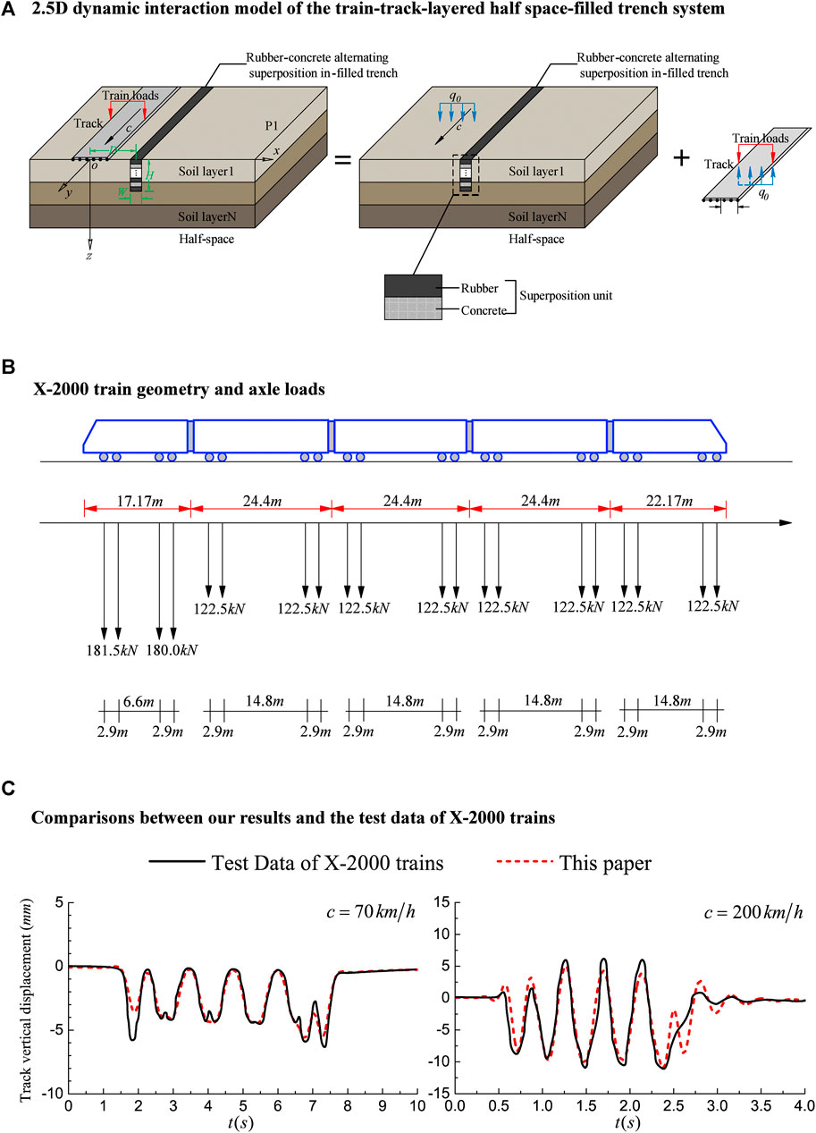
FIGURE 1. Model information.
When solving the flexibility of the layered elastic foundation with an in-filled trench under the moving load, one section of the vertical track can be used for the solution, and the dynamic response caused by the moving load at the section can be calculated. Then, according to the speed of the train, the remaining cross-sections are shifted to the corresponding phase, and the dynamic response generated at the other cross-sections is obtained. For solving the flexibility of the layered half-space with in-filled trench under moving load, this paper divides the layered half-space with in-filled trench into two parts: the layered half-space outside the in-filled trench and the soil layer inside the in-filled trench. The total wave field of the layered elastic half-space outside the in-filled trench includes the free field and the scattered wavefield, and the wavefield of the soil layer inside the in-filled trench only includes the scattered wave field. The free wave field is defined as the dynamic response (displacement and stress) of a layered half-space without an in-filled trench under a moving load, which is solved by the direct stiffness method. The scattered wavefield is defined as the additional wavefield generated by the scattering due to the existence of the in-filled trench, which is simulated by applying two sets of virtual moving uniformly distributed line loads on the boundary of the in-filled trench. This method is called the moving Green’s function method. The density of the virtual moving uniformly distributed line loads can be determined by the corresponding boundary conditions. Finally, the total wave field of the layered elastic half-space outside the in-filled trench is the superposition of the free wave field and the scattered wavefield, that is, the flexibility of the layered elastic half-space containing the in-filled trench under the action of moving uniformly distributed vertical load is obtained.
The Flexibility of the Layered Half-Space with In-Filled Trench
The stiffness matrix given in [29] can be adopted for the dynamic stiffness matrix of the 3D layered foundation
where
Here,
Among them,
For the scattered wavefield caused by the in-filled trench, let
Here, the subscripts “u” and “t”, respectively, represent the displacement and stress Green’s function; the subscript “G” represents the dynamic response caused by the moving uniform distributed line load; the superscripts “D” and “S”, respectively, represent the layered elastic half-space outside the in-filled trench and the elastic soil layer inside the in-filled trench.
The continuous conditions of stress and displacement on the interface s of the in-filled trench can be expressed as
Here,
where
From Eq. 6, the virtual moving uniform distributed line loads
Among them,
Coupling of the Layered Foundation and the Track
Assuming that the interaction pressure density between the track and the foundation is
Here,
Considering that the displacement of each point of the track in the transverse direction is
Here,
Method Verification
This paper verifies the correctness of the numerical analysis of this paper by comparing the calculated results with the actual measured data of the Swedish X-2000 train [32]. In this section, the material parameters in the in-filled trench are taken as the same as the parameters of the soil layer, that is, the half-space with the in-filled trench degenerates into the half-space without an in-filled trench. Table 1 and Table 2, respectively, give the foundation soil parameters and the track system parameters of the Swedish X2000 train at different speeds. The Swedish X2000 train consists of five carriages, and the load distribution of the train wheels is shown in Figure 1B. Figure 1C shows the comparison between the calculated results in this paper and the measured data when the train speeds are 70 km/h and 200 km/h, respectively. The results in this paper are in good agreement with the measured data, which confirms the reliability of the method in this paper.
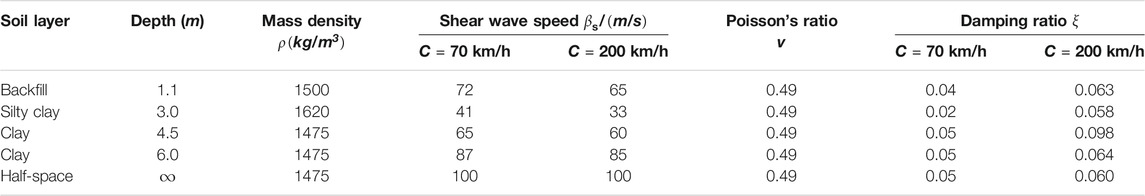
TABLE 1. Soil parameters under train speeds of 70 and 200 km/h
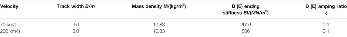
TABLE 2. Track properties
Vibration Isolation of the Rubber-Concrete Alternating Superposition In-Filled Trench
To better demonstrate the superiority of the rubber-concrete alternating superposition in-filled trench for train-induced vibration isolation, this paper takes the vibration generated by the Sweden X2000 high-speed train on the actual soft soil foundation as an example, and compares the vibration isolation effect with that of the empty trench, rubber in-filled trench, and C30 concrete in-filled trench. In the calculation, the thickness of the rubber-C30 superposition unit is taken as 0.4 m, and the trench with 3.0 m depth and 0.5 m width. The actual soft soil foundation parameters of the Sweden X-2000 high-speed train can be found in [33]. The track parameters of the X-2000 train are shown in Table 2, and the wheel axle load distribution is shown in Figure 1B. Figure 2A shows the results of the vertical displacement, velocity, and acceleration time histories of point P1 in Figure 1A when the speeds of the X2000 train are 70 km/h and 200 km/h, with different types of in-filled trench. Figure 2B shows the Fourier amplitude spectrum of the vertical displacement, velocity, and acceleration at point P1 corresponding to Figure 2A.
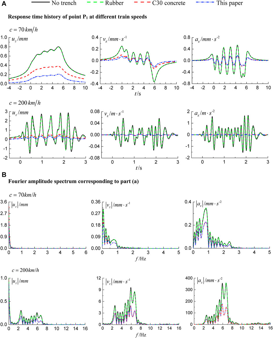
FIGURE 2. Influence of trench type to isolation effect on soft soil.
It can be seen from Figure 2A that the rubber-filled trench has almost no vibration isolation effect. At the two speeds of the train, the vibration isolation effect of the rubber-concrete alternately superposition in-filled trench proposed in this paper is significantly better than that of the C30 concrete in-filled trench, which is especially reflected in the vibration isolation effect on displacement. Moreover, the vibration isolation effect of the rubber-concrete alternately superposition in-filled trench at the speed of 200 km/h is better than that of the speed of 70 km/h. Figure 2B shows that the frequency spectrum of ground vibration response behind the trench is significantly changed by the rubber-concrete alternately superposition in-filled trench. Compared with low-frequency vibrations generated by the lower train speed, the rubber-concrete alternately superposition in-filled trench has a better vibration isolation effect on high-frequency vibrations generated by a high-speed train. This shows that the rubber-concrete alternately superposition in-filled trench has the frequency band characteristics of elastic waves, that is, elastic waves in the passband frequency range can propagate without attenuation, while the elastic waves in the forbidden frequency range will be filtered out.
Conclusion
This paper presented a new train-induced vibration isolation measure of rubber-concrete alternating superposition in-filled trench and built a 2.5D train-track-layered foundation-filled trench model to analyze the dynamics of track and layered foundation with the in-filled trench. The correctness of the model is verified by using the measured data of the Sweden X2000 high-speed train. Finally, the vibration isolation efficiency of rubber-concrete alternating superposition in-filled trench is calculated using the actual soft soil foundation parameters of the Sweden X2000 high-speed train, and the vibration isolation efficiency is compared with that of the empty trench rubber in-filled trench and concrete in-filled trench. The results show that the vibration isolation effect of the rubber-concrete alternating superposition in-filled trench proposed in this paper is better than that of the C30 concrete in-filled trench, especially the impact on displacement. Compared with low-frequency vibrations generated by the lower train speed, the rubber-concrete alternating superposition in-filled trench has a better vibration isolation effect on high-frequency vibrations caused by higher-speed trains.
Data Availability Statement
The original contributions presented in the study are included in the article/Supplementary Material. Further inquiries can be directed to the corresponding author.
Author Contributions
Conceptualization: JW and QL; mathematical derivation: LJ and JW; computer program: LJ and JW; validation and data curation: XL and ZZ; writing: original draft preparation, review, and editing, LJ and JW All authors have read and agreed to publish this manuscript.
Funding
This study is supported by the Youth Technology Innovation Funds in Shanxi Agricultural University (No. 2018009), which is gratefully acknowledged.
Conflict of Interest
The authors declare that the research was conducted in the absence of any commercial or financial relationships that could be construed as a potential conflict of interest.
Publisher’s Note
All claims expressed in this article are solely those of the authors and do not necessarily represent those of their affiliated organizations, or those of the publisher, the editors, and the reviewers. Any product that may be evaluated in this article, or claim that may be made by its manufacturer, is not guaranteed or endorsed by the publisher.
References
2. Yang Y-B, Hung H-H. A Parametric Study of Wave Barriers for Reduction of Train-Induced Vibrations. Int J Numer Meth Engng (1997) 40:3729–47. doi:10.1002/(sici)1097-0207(19971030)40:20<3729:aid-nme236>3.0.co;2-8
3. With C, Bahrekazemi M, Bodare A. Wave Barrier of Lime-Cement Columns against Train-Induced Ground-Borne Vibrations. Soil Dyn Earthquake Eng (2009) 29:1027–33. doi:10.1016/j.soildyn.2008.12.005
4. Gao G, Peng Z, Zhang M. Analysis of Passive Vibration Isolation Using Open Trench in Layered Ground. Northwest Seismological J (2009) 31(2):115–20. (in Chinese).
5. Zhang L, Liu J, Hou E. Model Test Research on Vibration Isolation Effects of Filling Barriers for Railway Subgrade. Railway Eng (2017) 2 (4) 146–50. (in Chinese). doi:10.1007/978-981-15-2349-6_3
6. Bi Q, Zhao Q, Liu J. The Research on the Model Test of the Effect of Vibration Isolation about Continuous Vibration Isolation Measures in High Speed Railway. J Railway Sci Eng (2018) 15(4):829–36. (in Chinese).
7. Brûlé S, Javelaud EH, Enoch S, Guenneau S. Experiments on Seismic Metamaterials: Molding Surface Waves. Phys Rev Lett (2014) 112(13):133901. doi:10.1103/physrevlett.112.133901
8. Beskos DE, Dasgupta B, Vardoulakis IG. Vibration Isolation Using Open or Filled Trenches. Comput Mech (1986) 1(1):43–63. doi:10.1007/bf00298637
9. Adam M, Von Estorff O. Reduction of Train-Induced Building Vibrations by Using Open and Filled Trenches. Comput Structures (2005) 83:11–24. doi:10.1016/j.compstruc.2004.08.010
10. Hung HH, Yang YB, Chang DW. Wave Barriers for Reduction of Train-Induced Vibrations in Soils. J Geotech Geoenviron Eng (2004) 130(12):1283–91. doi:10.1061/(asce)1090-0241(2004)130:12(1283)
11. Andersen L, Nielsen SRK. Reduction of Ground Vibration by Means of Barriers or Soil Improvement along a Railway Track. Soil Dyn Earthquake Eng (2005) 25(7):701–16. doi:10.1016/j.soildyn.2005.04.007
12. Deng Y, Xia T, Chen J. Analysis of Efficiency of Vibration Isolating Groove Subjected to Vehicle Load. Rock Soil Mech (2007) 28(5):883–8. (in Chinese).
13. Hildebrand R. Asymptotic Analysis of Hard Wave Barriers in Soil. Soil Dyn Earthquake Eng (2003) 23(2):143–58. doi:10.1016/s0267-7261(02)00154-9
14. Jesmani M, Shafie MR, Sadeghi Vileh R. Finite Element Analysis of Active Isolation of Deep Foundation in Clayey Soil by Rectangular Trenches. Electron J Geotechnical Eng (2008) 13:143–52.
15. Tsai PH. Effects of Open Trench Dimension on Screening Effectiveness for High Speed Train Induced Vibration. Appl Mech Mater (2013) 256:1187–90. doi:10.4028/www.scientific.net/AMM.256-259.1187
16. Zakeri J-A, Esmaeili M, Mosayebi S-A. Numerical Investigation of the Effectiveness of a Step-Shaped Trench in Reducing Train-Induced Vibrations. Proc Inst Mech Eng F: J Rail Rapid Transit (2014) 228(3):298–306. doi:10.1177/0954409712473094
17. Kim HS. A Study on the Characteristics and the Effective Reduction Methods for the Ground Vibration Due to the Travelling Tilting Train. Eng (2014) 06:202–9. doi:10.4236/eng.2014.64024
18. Chiang C-h, Tsai P-h. A Numerical Study of the Screening Effectiveness of Open Trenches for High-Speed Train-Induced Vibration. Shock and Vibration (2014) 2014:1–11. doi:10.1155/2014/489090
19. Esmaeili M, Zakeri JA, Mosayebi SA. Investigating the Optimized Open V-Shaped Trench Performance in Reduction of Train-Induced Ground Vibrations. Int J Geomechanics (2013) 14(3):04014004.
20. Linag J, Ba Z. Surface Motion of an Alluvial valley in Layered Half-Space for Incident Plane SH Waves. J Earthquake Eng Eng Vibration (2007) 27(3):1–9. (in Chinese).
21. Banerjee PK, Ahmad S, Chen K. Advanced Application of BEM to Wave Barriers in Multi-Layered Three-Dimensional Soil media. Earthquake Engng Struct Dyn (1988) 16(7):1041–60. doi:10.1002/eqe.4290160707
22. Leung KL, Beskos DE, Vardoulakis IG. Vibration Isolation Using Open or Filled Trenches. Comput Mech (1990) 7(2):137–48. doi:10.1007/bf00375927
23. Karlström A, Boström A. Efficiency of Trenches along Railways for Trains Moving at Sub- or Supersonic Speeds. Soil Dyn Earthquake Eng (2007) 27:625–41. doi:10.1016/j.soildyn.2006.12.005
24. Di Mino G, Giunta M, Di Liberto CM. Assessing the Open Trenches in Screening Railway Ground-Borne Vibrations by Means of Artificial Neural Network. Adv Acoust Vibration (2009) 2009:1–12. doi:10.1155/2009/942787
25. Sivakumar Babu GL, Srivastava A, Nanjunda Rao KS, Venkatesha S. Analysis and Design of Vibration Isolation System Using Open Trenches. Int J Geomechanics (2010) 11(5):364–9. doi:10.1061/(asce)gm.1943-5622.0000103
26. Connolly D, Giannopoulos A, Fan W, Woodward PK, Forde MC. Optimising Low Acoustic Impedance Back-Fill Material Wave Barrier Dimensions to Shield Structures from Ground Borne High Speed Rail Vibrations. Construction Building Mater (2013) 44:557–64. doi:10.1016/j.conbuildmat.2013.03.034
27. Jiang J, Toward MGR, Dijckmans A, Thompson DJ, Degrande G, Lombaert G, Ryue J. Reducing Railway Induced Ground-Borne Vibration by Using Trenches and Buried Soft Barriers. In: Noise and Vibration Mitigation for Rail Transportation Systems; Berlin, Heidelberg. Springer (2015). p. 555–62. doi:10.1007/978-3-662-44832-8_65
28. Yuan W, Cai Y, Shi L. Study of Vibration-Isolation Efficiency of Open Trench in Saturated Ground by 2.5D Finite Element Method. Rock Soil Mech (2013) 34(7):2111–8. (in Chinese).
29. Liang J, Ba Z. Exact Dynamic Stiffness Matrices of 3-D Layered Site and its Green's Functions. J Earthquake Eng Eng Vibration (2007) 27(5):7–17. (in Chinese).
30. Ba Z, Liang J, Jin W, Dynamic Responses of Layered Ground-Track Coupled System under the Moving Loads from High-Speed Train. China Civil Eng J (2014) 47(11):108–19. (in Chinese).
31. Ba Z, Wang J, Liang J, Reduction of Train-Induced Vibrations by Using a Trench in a Layered Half-Space. J Vibroeng (2016) 18(3):1742–64. doi:10.21595/jve.2016.16566
32. Takemiya H. Simulation of Track-Ground Vibrations Due to a High-Speed Train: the Case of X-2000 at Ledsgard. J Sound Vibration (2003) 261(3):503–26. doi:10.1016/s0022-460x(02)01007-6
Keywords: rubber-concrete alternating superposition in-filled trench, isolation trench, trains moving loads, 2.5D indirect boundary element method (IBEM), layered foundation
Citation: Jin L, Wang J, Liu X, Li Q and Zhou Z (2021) Vibration Isolation of a Rubber-Concrete Alternating Superposition In-Filled Trench for Train-Induced Environmental Vibration Based on 2.5D Indirect Boundary Element Method. Front. Phys. 9:774621. doi: 10.3389/fphy.2021.774621
Received: 12 September 2021; Accepted: 11 October 2021;
Published: 26 November 2021.
Edited by:
Qingxiang Meng, Hohai University, ChinaReviewed by:
Chen Su, Beijing University of Technology, ChinaZhang Ji, East China Jiaotong University, China
Copyright © 2021 Jin, Wang, Liu, Li and Zhou. This is an open-access article distributed under the terms of the Creative Commons Attribution License (CC BY). The use, distribution or reproduction in other forums is permitted, provided the original author(s) and the copyright owner(s) are credited and that the original publication in this journal is cited, in accordance with accepted academic practice. No use, distribution or reproduction is permitted which does not comply with these terms.
*Correspondence: Jingya Wang, jingyawang1220@163.com