A Tunable low Pass Filter Based on Transmission Lines With Tunable Input/Output Impedance
 Zhonghai Zhang
 Yuekai Zhao1
 - 1Institute of Antenna and Microwave, Hangzhou Dianzi University, Hangzhou, China
- 2National Key Laboratory of Science and Blind Signal Processing, Chengdu, China
A tunable low pass filter (TLPF) based on the tuning of input/output impedance was presented in this letter. The TLPF mainly consisted of improved quarter-wavelength stubs. The input/output impedance of the improved quarter-wavelength stubs can be tuned in a certain range. The design procedure of this TLPF was derived from the filters based on the quarter-wavelength transmission stubs. Through the tuning of the input/output impedance of the transmission lines, the cut-off frequency of the TLPF can be adjusted in a certain range. The TLPF has relatively good designability and can be easily changed to meet other performance levels. Finally, a TLPF was designed, fabricated, and measured. The measured results verify the effectiveness of the design method.
Introduction
As a key component in wireless communication systems, the filter can suppress the interference signal at the outband. A tunable filter can be applied to reconfigurable communication systems and has been widely studied [1–13]. The cut-off frequency of the tunable low pass filter (TLPF) can be adjusted according to the actual application which can be applied in a variety of communication systems with different parameters and has been studied widely [6–13]. The design methods of the TLPF can be summarized into three types. Firstly, some resonators with a special structure can realize a TLPF [6–9]. In this method, due to the particularity of the resonator structure, it was difficult to realize a TLPF to meet other requirements. Secondly, through the tuning of parameters, such as dielectric constant and permeability of the substrate, can also realize a tunable low pass filter [10, 11]. But in this method, the tuning range was relatively small. Thirdly, the improvement of the low pass prototype can also realize a TLPF [12, 13]. In this method, the change of the cut-off frequency can be achieved through the tuning of the capacitors or inductors in the LPF. It is difficult to achieve a tunable inductor in an LPF. Therefore, it is difficult to realize a wide tuning range for the cut-off frequency. Therefore, there are few studies on TLPFs with a larger cut-off frequency tuning range and better designability simultaneously.
Starting from the low pass filter equivalent circuit based on quarter-wavelength stubs, this letter attempts to achieve a TLPF based on the tuning of the input/output impedance of the transmission line in the equivalent circuit model. At the same time, the cut-off frequency tuning range of the TLPF can also be expanded. The resonators of the TLPF mainly consisted of step impedance lines loaded with tunable reactance at the connections of the high and low impedance lines and the open ends. The improved quarter-wavelength line between the resonators was mainly achieved with the transmission lines parallel to tunable reactances. Through the tuning of the tunable reactances loaded in the improved quarter-wavelength lines, the cut-off frequency of the TLPF can also be tuned in a certain range. Compared with the traditional TLPF that achieves frequency tuning by adjusting the electrical length of the resonators [11–13], by inserting the step impedance lines and the transmission lines parallel to tunable reactances, the tuning range of the TLPF can be further expanded.
Analysis of the Equivalent Circuit of the TLPF
The equivalent circuit of the TLPF is shown in Figure 1.
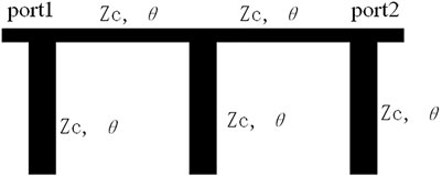
FIGURE 1. The equivalent circuit of the TLPF.
In Figure 1, the open end stubs represent capacitance. The transmission lines between open end stubs represent inductance. The tuning of the electronic length θ can achieve the tuning of the cut-off frequency. But it was difficult to achieve the tuning of the electronic length θ for the transmission lines between open end stubs.
According to the design method of low pass filters based on quarter-wavelength transmission lines, in addition to the electrical length tuning, the cut-off frequency of the low pass filter can also be tuned in a certain range through the adjusting of the characteristic impedance Z of the transmission lines. The simulated results are shown in Figure 2.

FIGURE 2. The tuning of the low pass filter.
In Figure 2, only through the tuning of the characteristic impedance can the cut-off frequency of the low pass filter be tuned from 430 to 670 MHz. The relative bandwidth of tuning was 43.6%. Beyond this range, the ripple and return loss performance in the passband of the low pass filter will deteriorate sharply.
Obviously, the combination of the characteristic impedance tuning and electronic length θ tuning of the transmission lines can achieve a wider cut-off frequency tuning range.
Design of TLPF Based on Tunable Input/Output Impedance
For a transmission line, it was very difficult to adjust the characteristic impedance. But the tuning of the input/output impedance can be realized through inserting a tunable reactance parallel to the transmission lines. The feature of the input/output impedance tuning was similar to the tuning of the characteristic impedance. Therefore, the tuning of the input/output impedance of the transmission lines can be adopted to achieve a TLPF.
The schematic of the designed TLPF is shown in Figure 3.
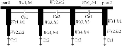
FIGURE 3. The schematic of the designed TLPF.
In Figure 3, the transfer matrix can be derived as follows.
In Eq. 1, Z1 and Z3 are the port impedances of the stepped impedance line loaded with tunable capacitors at the open ends of the first/fourth and second/third sections, respectively. Z2 and Z4 are the total input impedance of the quarter-wavelength transmission line parallel to the tunable capacitors Cc1 and Cc2, respectively. The expression of Z2 was as follows:
Substituting Eq. 2 into Eq. 1, the transmission matrix of the entire TLPF can be obtained and T21 was the transmission characteristic of the filter. The calculation method of Z4 was similar to that of Z2.
Through the tuning of the capacitors Cc1 and Cc2, the tuning of the input/output impedance can be realized. The size of the schematic in Figure 3 was optimized (ws1 = 1.6 mm, ls1 = 10.7 mm, ws2 = 1.5 mm, ls2 = 13 mm, ws3 = 6.8 mm, ls3 = 21 mm, ws4 = 3 mm, ls4 = 11 mm, wc1 = 0.7 mm, lc1 = 63 mm, wc2 = 0.8 mm, lc2 = 94 mm). With the tuning of Cc1 and Cc2, the simulated transmission performance of the TLPF is shown in Figure 4.
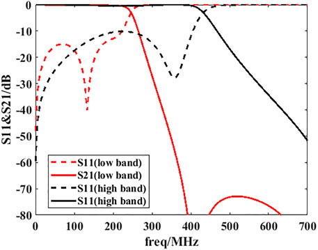
FIGURE 4. The curve of transmission performance with Cc.
From Figure 4, the cut-off frequency of the tunable LPF can be tuned from 220 to 404 MHz providing Cc tuning from 1 pf to 8 pf. The return loss of the passband was less than −10 dB. Beyond this frequency tuning range, the return loss of the tunable filter in the passband will deteriorate sharply.
Fabrication and Measurement of TLPF Based on Tunable Input/Output Impedance
To verify the effectiveness of the design method described in this letter, a TLPF with seven resonators was designed, fabricated, and measured. The Logers 4350b substrate was selected to realize this TLPF. The dielectric constant of this substrate was 3.48 and thickness was 40 mm. In order to expand the tuning range of the filter further, tunable capacitors were introduced at the connection of the high and low impedance lines. In order to obtain a larger tuning range, the size of the TLPF in this letter has been optimized. The layout of the TLPF is shown in Figure 5. The dimensions of the TLPF were the same as the ones in Figure 3. The fabricated TLPF is shown in Figure 6.
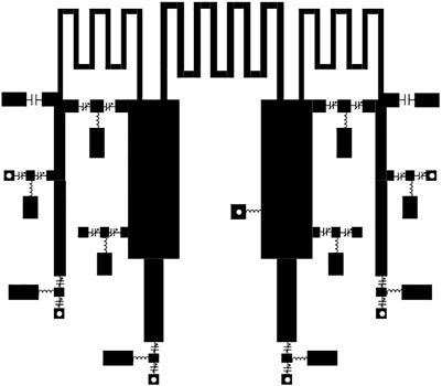
FIGURE 5. The layout of the TLPF.
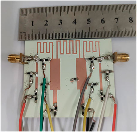
FIGURE 6. The fabricated TLPF. The measured performance is shown in Figure 7.
Due to the insertion of capacitors at the connections and open ends of the high and low impedance lines, the cut-off frequency tuning range of the TLPF was expanded compared to the situation with only input and output impedance tuning. As seen in Figure 7, the cut-off frequency of the TLPF can be tuned from 220 to 440 MHz, the relative bandwidth tuning range was 66.7%. The return loss of the TLPF was better than 10 dB. The insertion loss was better than 0.5 dB.
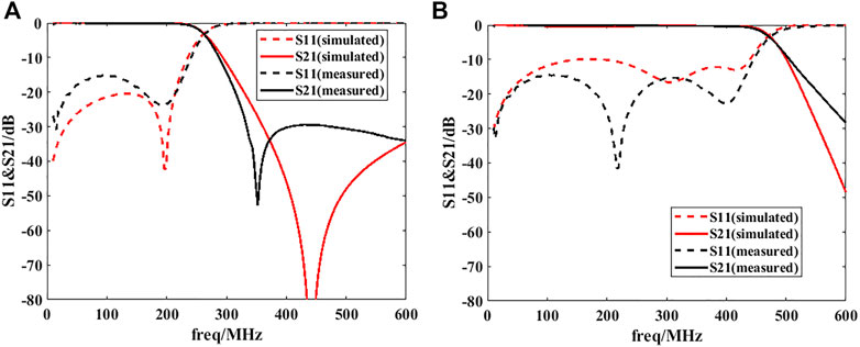
FIGURE 7. (A) The measured performance of the TLPF (220 MHz). (B) The measured performance of the TLPF (440 MHz).
The TLPF proposed in this article has good designability and can be designed into a TLPF that meets other performance requirements easily the comparison between the proposed TLPF and the references (Table 1).
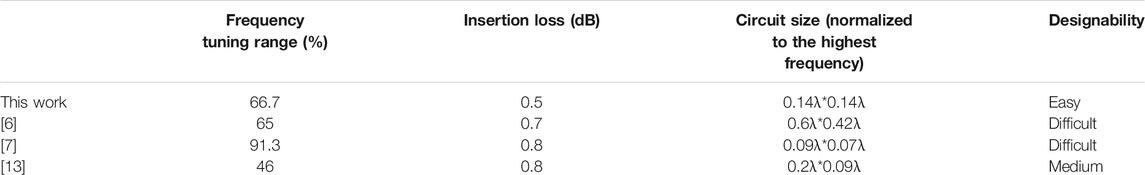
TABLE 1. Comparison between the proposed TLPF and the references.
Conclusion
A tunable low pass filter adopting tunable input/output impedance technology was presented. Through the tuning of input/output impedance of the quarter-wavelength resonator, the cut-off frequency of the TLPF can be tuned in a certain range. The design of the TLPF based on variable input/output impedance can be generalized to other types of filters and filter designs with other properties.
Data Availability Statement
The original contributions presented in the study are included in the article/supplementary material, further inquiries can be directed to the corresponding author.
Author Contributions
All authors listed have made a substantial, direct, and intellectual contribution to the work and approved it for publication.
Conflict of Interest
The authors declare that the research was conducted in the absence of any commercial or financial relationships that could be construed as a potential conflict of interest.
Publisher’s Note
All claims expressed in this article are solely those of the authors and do not necessarily represent those of their affiliated organizations, or those of the publisher, the editors and the reviewers. Any product that may be evaluated in this article, or claim that may be made by its manufacturer, is not guaranteed or endorsed by the publisher.
References
1. Ouyang ZA, Qiu LL, Zhu L. Coplanar Waveguide Serially Connected Coplanar Strip Dual Stub Structure for Wideband Bandpass Filters. Int J RF Microw Comput Aided Eng (2021) 31(4):225–9. doi:10.1002/mmce.22571
2. Guan XH, Huang W, Ren BP. High Isolation Tunable Diplexer Based on Mixed Electromagnetic Coupling. Int J RF Microw Comput Aided Eng (2018) 2863(23):1–7. doi:10.1002/mmce.21199
3. Huang ZW, Cheng Y. Cross-coupled Dielectric Waveguide Filter. Int J RF Microw Comput Aided Eng (2021) 63(3):8–14. doi:10.1002/mmce.22585
4. Vkumar K, Mukherjee B. Compact Dual Bandpass Filter for Terrestrial Radio and GSM Applications. Int J RF Microw Comput Aided Eng (2017) 27(8):1–8. doi:10.1002/mmce.21131
5. Iqbal A, Smida A, Waly MI, Mallat NK. Highly-tunable and Wide Stopband Microstrip Bandpass Filters. Int J RF Microw Comput Aided Eng (2021) 31:1–6. Early Access. doi:10.1002/mmce.22610
6. Huang CC, Chen NW, Tsai HJ, Chen JY. A Coplanar Waveguide Bandwidth-Tunable Lowpass Filter with Broadband Rejection. IEEE Microw Wireless Compon Lett (2013) 23(3):134–6. doi:10.1109/lmwc.2013.2242323
7. Cai C, Wang J, Zhang G. Tunable Microstrip Lowpass Filter with Compact Size and Ultra‐wide Stopband[J]. Electron Lett (2015) 51(19):1514–6. doi:10.1049/el.2015.0829
8. Kumar L, Parihar MS. A Compact Reconfigurable Low-Pass Filter with Wide-Stopband Rejection Bandwidth. IEEE Microw Wireless Compon Lett (2018) 28(5):401–3. doi:10.1109/lmwc.2018.2823001
9. Kumar N, Singh YK. Compact Tunable Low‐pass to CFBW Bandpass Switchable Filter Using Concentric Resonators. IET Microwaves, Antennas & Propagation (2018) 12(14):2225–33. doi:10.1049/iet-map.2018.5345
10. Yang G-M, Wu J, Lou J, Liu M, Sun NX. Low-Loss Magnetically Tunable Bandpass Filters with YIG Films. IEEE Trans Magn (2013) 49(9):5063–8. doi:10.1109/tmag.2013.2253114
11. Yun Zhu Y, Gang Qiu G, Chi KH, Wang BBT, Tsai CS. A Tunable X-Band Band-Pass Filter Module Using YIG/GGG Layer on RT/Duroid Substrate. IEEE Trans Magn (2009) 45(10):4195–8. doi:10.1109/tmag.2009.2022642
12. Zhang R, Mansour RR. Novel Digital and Analogue Tunable Lowpass Filters. IET Microw Antennas Propag (2007) 1(3):549–55. doi:10.1049/iet-map:20060263
Keywords: tunable filter, tunable impedance, cut off frequency, characteristic impedance, input/output impedance
Citation: Zhang Z, Zhao Y, Chen L, Fang Z, Wu A and Zhang P (2022) A Tunable low Pass Filter Based on Transmission Lines With Tunable Input/Output Impedance. Front. Phys. 10:872204. doi: 10.3389/fphy.2022.872204
Received: 09 February 2022; Accepted: 18 February 2022;
Published: 25 March 2022.
Edited by:
Kai-Da Xu, Xi’an Jiaotong University, ChinaReviewed by:
Feng Wei, Xidian University, ChinaJi Laiyun, Tianjin Hi-Tech Superconducting Electronic Technology, China
Copyright © 2022 Zhang, Zhao, Chen, Fang, Wu and Zhang. This is an open-access article distributed under the terms of the Creative Commons Attribution License (CC BY). The use, distribution or reproduction in other forums is permitted, provided the original author(s) and the copyright owner(s) are credited and that the original publication in this journal is cited, in accordance with accepted academic practice. No use, distribution or reproduction is permitted which does not comply with these terms.
*Correspondence: Pengquan Zhang, zhpq1999@163.com