GNSS Spoofing Suppression Based on Multi-Satellite and Multi-Channel Array Processing
 Shaojie Ni
  Binbin Ren
 Zukun Lu
 Jie Wang
 Yifan Sun
- Department of Electronic Science and Technology, National University of Defence Technology, Changsha, China
The endless spoofing interference affects the credibility of the navigation system seriously. In order to suppress the forward spoofing which is more threatening to military signals in GNSS, this paper proposes a spoofing suppression algorithm based on angle of arrival estimation and multi-satellite fusion. On the basis of successfully suppressing the spoofing signal, the algorithm improves the estimation accuracy of the angle of arrival of the forwarded spoofing and reduces the attenuation of the carrier to noise ratio of the real satellite signal. Finally, the effectiveness of the algorithm is verified by simulation, which has guiding significance for the anti-spoofing research of GNSS.
1 Introduction
Global Navigation Satellite System (GNSS) is a space-based radio navigation and positioning system that can provide users with all-weather location, navigation, and timing information. At present, the world’s four major global satellite navigation system suppliers are: the GPS system of the United States, the “Beidou-3″ satellite navigation system of People’s Republic of China, the GLONASS system of Russia, and the Galileo system of Europe Union [1]. Japan and India are also focusing on the regional satellite navigation system research in their own countries [2]. From transportation in the civilian field [3], weather forecasting [4], power system [5], smart wear, hydrological monitoring [6], disaster relief [7], financial security [8], to individual combat in the military field Satellite navigation systems play an irreplaceable role in all aspects such as precision strikes, and sea escort [9, 10].
Since the civilian signal systems of navigation signals are open, its terminals are very vulnerable to spoofing and jamming. Spoofing and jamming means that the spoofing party enters the acquisition and tracking loop of the GNSS receiver by forging false signals with the same structure as the real satellite signal but different positioning or timing information or forwarding the real satellite navigation signal, so that the navigation user terminal can solve the wrong Positioning, Navigation and Timing (PNT) information, thus not working properly [11, 12]. Spoofing interference is mainly divided into: generative spoofing and forwarding spoofing. Among them, the message and spreading code of the civil code are public, and the deceiver can easily forge the navigation signal. Therefore, the research on the suppression of forwarding spoofing is particularly important.
Research on spoofing is also widely carried out, among which spoofing detection and single-antenna spoofing suppression are the main ones. The methods of spoofing detection are signal quality monitoring [13, 14], parameter estimation [15], automatic gain control [16], residual vector analysis method [17], correlating antenna motion and carrier phase [18, 19], mobile internet detection [20] and correlating carrier phase with rapid antenna motion [21]. Spoofing inhibition is mainly based on single-antenna and Receiver Autonomous Integrity Monitoring (RAIM) processing: Lu Mingquan’s team of Tsinghua University proposed iterative RAIM and cooperative RAIM algorithms to detect and suppress forwarding spoofing interference [22]. [23] proposed a spoofing suppression method using pseudorange and carrier phase [24]. proposed a jamming suppression method based on estimating spoofing signal steering vector, which eliminated the spoofing signal by constructing an orthogonal projection matrix based on spoofing jamming, but its estimation accuracy was poor, which would affect its suppression effect [25]. proposed an anti-spoofing jamming method based on improved RAIM, which uses an iterative algorithm to detect and eliminate the meaning of suspected spoofing satellites, and achieve spoofing suppression at the signal layer. However, the iterative algorithm is computationally intensive, and cannot suppress the spoofing of multiple satellites being forwarded at the same time. In contrast, there are in-depth studies on the suppression of jamming at present [26], analyzed the performance of adaptive space-time array in anti-jamming processing [27], proposed the use of multi-level nested Wiener filters (MSNWF) to suppress narrowband interference [28], analyzed in detail the performance of using the power inversion algorithm to suppress jamming. Team from National University of Defense Technology designed a variety of anti-jamming algorithms through delay constraints [29, 30] and array element constraints [31–33], respectively, without reducing the anti-jamming performance, effectively improving the accuracy of pseudo-range measurements [34]. proposed a new algorithm for adaptive notch filtering and parametric spectral estimation of multiple narrowband or sinusoidal signals in an additive broadband process [35, 36]. designed anti-jamming algorithms from the temporal and spatial domains, respectively, to further improve the convergence speed.
As can be seen from the above, the current methods of spoofing suppression are still relatively based on single-antenna, array processing is rarely used, and they all have certain limitations. This paper proposes a multi-satellite and multi-channel array processing GNSS spoofing signal suppression algorithm. By estimating and weighting the angle of arrival (AOA) of the multi-satellite spoofing signal, the estimation accuracy of the AOA of the spoofing signal is improved, and then the spoofing signal is suppressed in the airspace by the orthogonal subspace method. The main structure of this paper is as follows: In the second section, the model of the antenna array receiving spoofed signals is introduced; In the third section, the error of estimating the arrival angle of only one satellite and its influence on the real signal carrier-to-noise ratio (CNR) are analyzed; In the fourth section, proposes a multi-satellite fusion AOA estimation spoofing suppression algorithm, and the algorithm is verified by simulation, and finally the full text is summarized.
2 Signal Model
It is assumed that the receiving antenna array of the navigation receiver is composed of N ideal omnidirectional array elements, as shown in Figure 1. The antenna array used in this paper is set as shown in Figure 2.
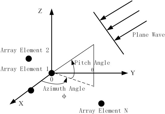
FIGURE 1. Schematic diagram of antenna array and incident signal.
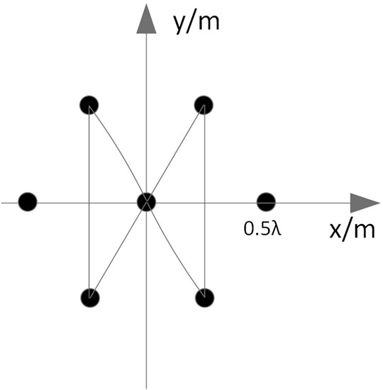
FIGURE 2. Schematic diagram of the arrangement of antenna array elements.
K navigation signals and L spoofing signals are incident on the antenna array as plane waves from the space far field, then the complex baseband form of the signal received by the navigation receiver antenna array can be expressed as:
where,
In the formula,
where (·)H represents the conjugate transpose operation.
The antenna array can use the spatial characteristics of the signal to filter the signal in the space-time field through weighting algorithms of different criteria. Among them, pure spatial filtering is the most basic method in array signal processing. Figure 3 shows the schematic diagram of antenna array spatial processing.
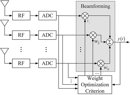
FIGURE 3. Schematic diagram of antenna array spatial filtering.
Each channel of the array input signal is multiplied by the weights (n = 1, 2... N) generated under a specific criterion, and then summed, and finally the array output signal is obtained, which is in the form:
In the formula,
3 Spoofing Suppression for Single-Satellite
In general, the energy of forwarding spoofing is greater than the real signal. Therefore, if the antenna array does not take anti-spoofing measures, the receiver will capture and track the spoofing signal and solve the message. Taking advantage of this feature, a single-satellite AOA estimation spoofing suppression algorithm is designed, and the algorithm processing flow is shown in Figure 4.
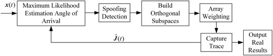
FIGURE 4. Algorithm processing block diagram.
The algorithm consists of three parts. The first is to reconstruct the spoofing signal for maximum likelihood estimation of the angle of arrival, which includes the spoofing detection link. The current satellite position is calculated from the message information of the received signal, and the angle of arrival is calculated and compared with the estimated value., if the deviation is too large, it is considered to be spoofing. By default, the detection and identification of the spoofing signal has been completed, so it will not be described in detail. Then, an orthogonal subspace is constructed according to the estimated angle of arrival of the spoofing signal, and the weights of the antenna array are generated to suppress the spoofing signal. The principle of maximum likelihood estimation of spoofing signals and the orthogonal subspace are introduced below, and the estimation performance and the influence of estimation error on spoofing suppression are analyzed.
3.1 Theoretical Analysis
3.1.1 Maximum Likelihood Estimation
Only considering when L signals are incident to the antenna array from the far field in the form of plane waves, Eq. 1 can be transformed into:
The noise is independent and identically distributed, and its autocorrelation matrix is
The l-th signal
where,
where,
The signal received by the antenna array can be expressed as:
When the waveform of the signal is known, the negative log-likelihood of the array output vector is:
where, m is the number of snapshots in the airspace,
Then the estimated likelihood function for the angle of arrival of a single signal is
During the solution process,
where,
According to the above likelihood function, for the estimation of the angle of arrival of a single satellite, we rearrange the
Then the estimated value of the angle of arrival of the signal is as follows:
So far, the angle of arrival of each signal can be estimated according to Eq. 23.
3.1.2 Orthogonal Subspace Spoofing Suppression Principle
When using the maximum likelihood method to estimate the AOA of the spoofing, the waveform of the spoofing signal
where,
Assuming that the repeating signals all come from the same repeating spoofing device, multiple satellite signals are delayed and forwarded. In this scenario, all spoofed signals have the same origin. After obtaining the angle of arrival information of the spoofing signal, substitute
Then the orthogonal subspace of the spoofing signal can be constructed:
The interference can be suppressed by projecting the array signal to the spoofed orthogonal subspace. The principle is shown in Figure 5.
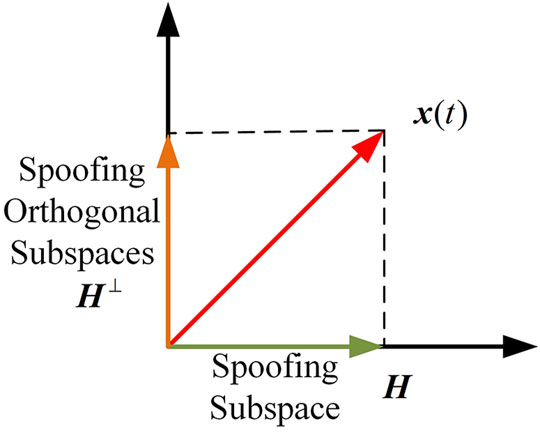
FIGURE 5. Schematic diagram of the principle of subspace projection.
The array output signal after projection is:
Therefore, it is only necessary to set the weight of the antenna array to a column in the orthogonal subspace which is not all zeros after normalization, that is, the spoofing can be eliminated from the airspace.
3.2 Influence of Estimation Accuracy on Real Signal Carrier-To-Noise Ratio
The maximum likelihood estimation algorithm is used to estimate the AOA of a single spoofing signal, and the Cramér–Rao bound theory formula of the estimated variance is:
where,
When using the maximum likelihood estimation algorithm to estimate the AOA of a spoofing signal, it is necessary to pay attention to its estimation accuracy under different power levels of the spoofed signal or the level of the carrier-to-noise ratio. In this section, the estimation accuracy of maximum likelihood estimation for the AOA of a single spoofed signal is simulated, as well as the Cramér–Rao bound at the current CNR of the spoofed signal.
According to the array structure shown in Figure 2, the specific setting parameters of the simulation scene are shown in Table 1.
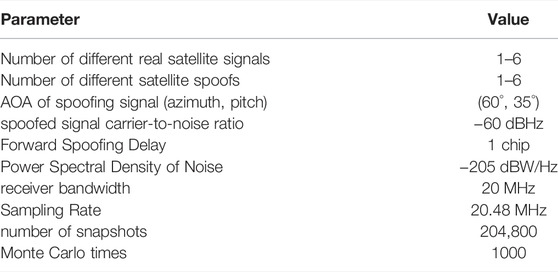
TABLE 1. Simulation parameter settings.
Figure 6 respectively show the changes of the azimuth and pitch variances of the maximum likelihood estimation and the corresponding Cramér–Rao bounds as the spoofing signal CNR gradually increases from 36 dBHz to 63 dBHz.
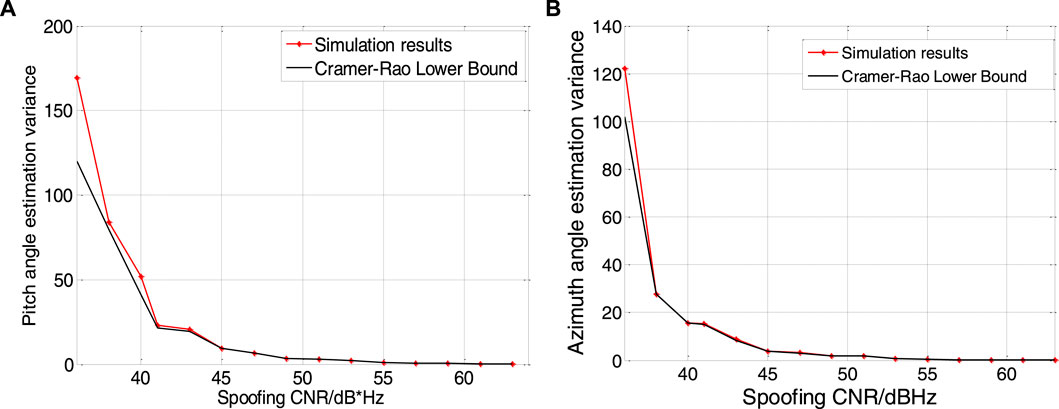
FIGURE 6. Angle of arriver estimation error. Result of pitch angle is shown in figure (A), and result of. azimuth angle is shown in figure (B).
As can be seen from Figure 6, when the carrier-to-noise ratio of the spoofed signal is low, the estimation accuracy of the azimuth and pitch angles is very poor. It can be seen that when the spoofing signal carrier-to-noise ratio is 36 dBHz, the estimated error of the azimuth angle reaches 5°, and the estimated error of the pitch angle is nearly 10°, while at 58 dBHz, the estimated error is close to 0.
The error of the AOA estimation will make the generated subspace not completely orthogonal to the spoofed signal, which will affect the suppression of the spoofed signal and cause the real signal to be suppressed as well. In order to analyze the influence of error on spoofing suppression and real signal, the following simulation analyzes the influence of the error of estimated azimuth and pitch angle on the real signal and spoofing signal output carrier-to-noise ratio after projection subspace processing. In this paper, only one real signal is considered, and its arrival pitch angle and azimuth angle are (70°, 100°), and the specific parameter settings are shown in Table 2.
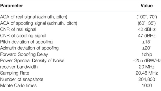
TABLE 2. Parameter setting of real and spoofing signals.
The effect results are shown in Figure 7.
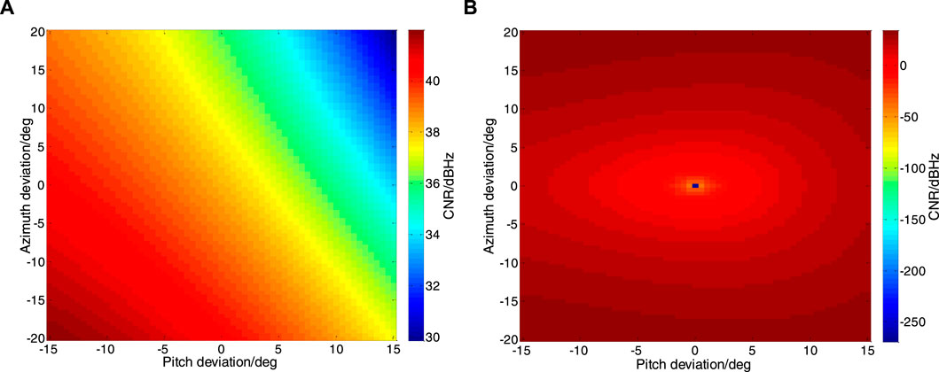
FIGURE 7. Effect of Arrival Angle Estimation Error on Signal Carrier-to-Noise Ratio. Real signal is. shown in figure (A), and spoofing signal is shown in figure (B).
As can be seen from Figure 7A, when the estimation error of the AOA of the spoofed signal is large, the carrier-to-noise ratio of the real signal will fluctuate accordingly. When the estimation error makes the arrival angle of the spoofed signal far away from the true signal azimuth, it will affect its carrier-to-noise ratio by about 2dB. When the estimation error makes the spoofed signal’s arrival angle close to the true signal azimuth, it will cause more than 10dB of attenuation to the carrier-to-noise ratio. As can be seen from Figure 7B, when the estimation error is large, the carrier-to-noise ratio of the spoofing signal suppressed by the orthogonal subspace algorithm will fluctuate greatly. When accurately estimated, the carrier-to-noise ratio tends to be infinitely small; when the azimuth angle deviation is 25° and the pitch angle deviation is 15°, the carrier-to-noise ratio is about 30 dBHz.
Through the above simulation and analysis, the estimation error of the angle of arrival of the spoofing signal will have a great impact on the performance of the receiver’s spoofing suppression, which will make the suppression of the spoofing signal worse, and cause greater attenuation of the real signal power, so that the receiver cannot normally capture and track the real signal. As a result, the normal positioning solution cannot be performed.
4 Multi-Satellite Fusion AOA Estimation Spoofing Suppression Algorithm
It can be seen from the above analysis that the error of AOA estimation for the spoofed signal will attenuate the power of the real signal. For satellite navigation systems, the power of the real signal is very weak, and this effect will make the receiver unable to capture the real signal. lose the ability to work properly, in response to this problem, this section proposes a multi-satellite fusion AOA estimation spoofing suppression algorithm, which estimates the AOA values of all current spoofing signals, according to the estimated variance corresponding to the carrier-to-noise ratio of each spoofing signal, the azimuth angle and the pitch angle are weighted respectively, which greatly improves the accuracy of the AOA estimation of the spoofing signal. Then the orthogonal subspace projection algorithm is used to suppress the spoofing. The algorithm processing flow is shown in Figure 8.
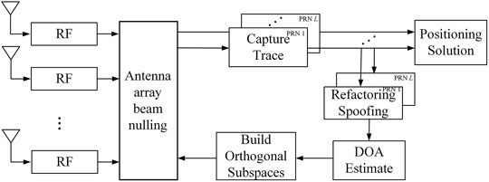
FIGURE 8. Schematic diagram of the algorithm structure.
Assuming that the number of satellites to be forwarded is L, the detailed processing steps of the algorithm are as follows:
1) The N array elements of the antenna array respectively receive the mixed signal containing the forwarding spoofing signal and the real signal, and obtain the intermediate frequency signal through the processing of the RF front-end;
2) The receiver captures and tracks the spoofed signal corresponding to each PRN number, reconstructs the local replica signal according to the pseudocode phase information output by the tracking loop, and estimates the carrier-to-noise ratio of each spoofed signal;
3) Using the reconstructed local replica signal, perform maximum likelihood estimation on the spoofing signal according to the method in Section 3 1, and obtain arrival angle information;
4) Calculate the estimated variance of the azimuth and elevation angles under the current carrier-to-noise ratio of the spoofed signal, and weight the azimuth and elevation angles with the variance basis respectively according to the principle of unequal precision weighting to achieve accurate estimation of the AOA of the spoofing;
5) Bring the weighted AOA value into Eq. 29, and use the orthogonal subspace algorithm to generate the antenna array weight to suppress deception.
4.1 AOA Estimation Fusion Weighting Algorithm
From the analysis in the previous section, it can be seen that for different carrier-to-noise ratios of spoofing signals, the accuracy of the maximum likelihood estimation of the AOA is also different. In order to improve the accuracy of the AOA estimation, this paper introduces the AOA estimation method of multi-satellite fusion weighting, the essence of which is to deal with the problem of unequal precision measurement.
In unequal precision measurement, each measurement result is obtained under different measurement conditions. The measurement conditions include: the measurement method, the instruments used in the measurement, the measurement personnel, the environmental conditions, and the measurement times when each result is obtained, etc. The difference in the accuracy of the measurement results is the result of the combined effect of these factors. Since the accuracy of each measurement result is not equal, the degree of trust in them is also different, which involves a so-called weight problem. The so-called weight is the quantitative performance of the relative reliability of each measurement result. For the content of this chapter, the different measurement conditions are the carrier-to-noise ratio of each spoofing signal, since the carrier-to-noise ratio of each satellite of the real signal reaching the receiving antenna of the transponder is different, after amplification and forwarding, the carrier-to-noise ratio of each satellite in the spoofed signal is also different. This causes the maximum likelihood to estimate the AOA of each satellite with different accuracy.
Assuming that the number of satellites to be relayed is L, the maximum likelihood estimates the pitch
From the above formula, the weighted pitch angle
In order to analyze the estimation accuracy under the algorithm, in this section, the estimation accuracy of the angle of arrival of the spoofing signal after the weighting of the algorithm is simulated, and compared with the estimation error of a single satellite.
Set the simulation scene as shown in Table 3, the antenna array is the 7-element center circular array shown in Figure 2.
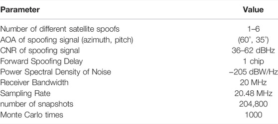
TABLE 3. Parameter setting of spoofing signal.
Assuming that the carrier-to-noise ratio with the PRN number one of the forwarding spoofing is P1, the remaining five satellite CNR settings are shown in Table 4.
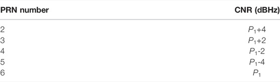
TABLE 4. Carrier-to-noise ratio settings.
The single-satellite estimation in the simulation process only estimates the satellite whose PRN number is 1, so the carrier-to-noise ratio of the abscissa corresponds to P1, The carrier-to-noise ratio of the abscissa of the multi-satellite fusion estimation is the largest carrier-to-noise ratio among all the forwarding satellites, which is equivalent to comparing the multi-satellite fusion estimation with only the spoofing signal with the highest carrier-to-noise ratio. Figure 9 show that as the CNR of the spoofed signal gradually increases from 36 dBHz to 61 dBHz, changes in azimuth and pitch variance for maximum likelihood estimates.
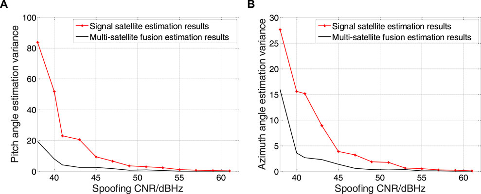
FIGURE 9. Angle of arriver estimation error. Result of pitch angle is shown in figure (A), and result of azimuth angle is shown in figure (B).
It can be clearly seen from Figure 9 that the estimation accuracy is improved by 80% when the CNR is 50 dBHz, the estimation accuracy under multi-satellite fusion has been greatly improved compared with that of single-satellite estimation.
4.2 Algorithm Simulation
In order to verify the simulation performance of the algorithm for spoofing suppression, the following simulations are carried out. The simulation conditions are: the real signal PRN numbers are one to six, and the values of the AOA, carrier-to-noise ratio and code phase are shown in Table 5.
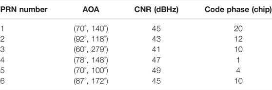
TABLE 5. Real satellite signal parameter settings.
The real navigation signal and the forwarding spoofing signal with a set delay of one chip and a spoofing-to-signal ratio of 10 dB are simulated. The forwarded signals all come from one direction (60°, 35°). The spoofing suppression algorithm is used to process the signal, and the software receiver is used to capture and process the processed signal to obtain the code phase of the output signal and the beam pattern of the antenna array to test the effect of the algorithm to suppress spoofing.
First, the code phase information captured by the software receiver is given, as shown in Figure 10.
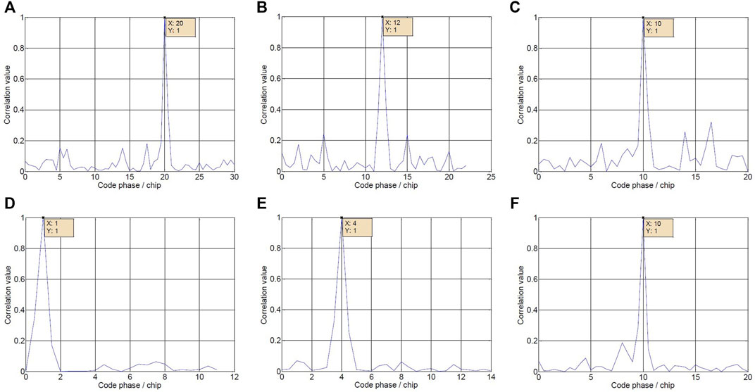
FIGURE 10. Code Phase Results. The captured results of PRN one to six satellites signal after algorithm processing are shown in figures (A–D).
As can be seen from Figure 10, after the signal processed by the algorithm is captured by the software receiver, its code phase is the code phase of the real satellite, which verifies the effectiveness of deception suppression.
The beam pattern of the antenna array at this time is shown in Figure 11.
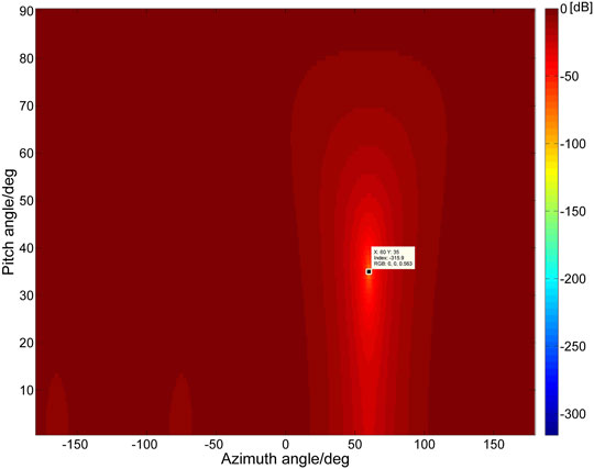
FIGURE 11. The beam pattern of the antenna array.
It can be seen that the antenna array accurately forms a 315.9dB null in the direction of the spoofing signal, which completely suppresses the spoofing signal. Analysis proves that the algorithm can accurately estimate the angle of arrival of forwarding spoofing, and can effectively suppress spoofing.
5 Conclusion
For the suppression of forwarding spoofing interference, this research proposed a multi-satellite and multi-channel array processing GNSS spoofing signal suppression algorithm. Firstly, the maximum likelihood estimation method is used to estimate the AOA of the current spoofing signals of all satellites, the estimated azimuth and pitch angles of each satellite are weighted and summed according to the estimated variance corresponding to the carrier-to-noise ratio of the spoofed signal, which improves the estimation accuracy of the AOA of the spoofed signal and reduces the impact on the CNR of the real signal. The simulation results show that in the case of different CNR of each satellite, the multi-satellite fusion estimation has a lower estimation error than the spoofing signal with the highest CNR. Then the orthogonal subspace of the spoofing signal is constructed, and the spoofing is suppressed in the airspace by using the antenna array weighting to form a null. Finally, by simulating real navigation signals, it is proved that the algorithm can accurately estimate the AOA of forwarding spoofing, and has a good spoofing suppression effect.
Data Availability Statement
The raw data supporting the conclusion of this article will be made available by the authors, without undue reservation.
Author Contributions
Conceptualization: SN and BR; methodology and validation: BR and FC; formal analysis and investigation: ZL and JW; resources: PM and YS; writing—original draft preparation: SN; writing—review and editing: BR and ZL; supervision: FC and PM; project administration: YS.
Funding
This research was funded by the National Natural Science Foundation of China (62003354 and U20A0193).
Conflict of Interest
The authors declare that the research was conducted in the absence of any commercial or financial relationships that could be construed as a potential conflict of interest.
Publisher’s Note
All claims expressed in this article are solely those of the authors and do not necessarily represent those of their affiliated organizations, or those of the publisher, the editors and the reviewers. Any product that may be evaluated in this article, or claim that may be made by its manufacturer, is not guaranteed or endorsed by the publisher.
Acknowledgments
The authors would like to thank the College of Electronic Sciences for providing the test platform.
References
1. Zhang Z, Pan L. Current Performance of Open Position Service with Almost Fully Deployed Multi-GNSS Constellations: GPS, GLONASS, Galileo, BDS-2, and BDS-3. Adv Space Res (2022) 69(5):1994–2019. doi:10.1016/j.asr.2021.12.002
2. Odijk D, Nadarajah N, Zaminpardaz S, Teunissen PJG. GPS, Galileo, QZSS and IRNSS Differential ISBs: Estimation and Application. GPS Solut (2017) 21(2):439–50. doi:10.1007/s10291-016-0536-y
3. Akhmedov D, Moldabekov M, Yeryomin D, Zhaxygulova D, Kaliyeva R. Application of the Automated Control System for Reference GNSS Station Network in the Transport Sector. J Phys Conf Ser (2020) 1626(1):012076. doi:10.1088/1742-6596/1626/1/012076
4. Rahimi Z, Mohd Shafri HZ, Norman M. A GNSS-Based Weather Forecasting Approach Using Nonlinear Auto Regressive Approach with Exogenous Input (NARX). J Atmos Solar-Terrestrial Phys (2018) 178:74–84. doi:10.1016/j.jastp.2018.06.011
5. Noack PO, Eder D, Bleisteiner N. Infuence of Electric Power Lines on the Reception of GNSS-Signals in Automatic Steering Systems. Landtechnik (2018) 73(3):52–61. doi:10.15150/lt.2018.3182
6. Materna K, Feng L, Lindsey EO, Hill EM, Ahsan A, Alam AKMK, GNSS Characterization of Hydrological Loading in South and Southeast Asia. J Int (2020) 224(3):1742–52. doi:10.1093/gji/ggaa500
7. Gao GX, Sgammini M, Lu M, Kubo N. Protecting GNSS Receivers from Jamming and Interference. Proc IEEE (2016) 104(6):1327–38. doi:10.1109/JPROC.2016.2525938
8. Jing D, He B, Silin L. Study of Key Issues for the Combat Application of GNSS. In: ICCDE' 19: Proceedings of the 2019 5th International Conference on Computing and Data Engineering; Shanghai, China, May 2019 (2019). doi:10.1145/3330530.3330533
9. Wang F, Yang D, Niu M, Yang L, Zhang B. Sea Ice Detection and Measurement Using Coastal GNSS Reflectometry: Analysis and Demonstration. IEEE J Sel Top Appl Earth Observations Remote Sensing (2022) 15:136–49. doi:10.1109/JSTARS.2021.3133431
10. Jiao J, Deng Z, Arain QA, Li F. Smart Fusion of Multi-Sensor Ubiquitous Signals of Mobile Device for Localization in GNSS-Denied Scenarios. Wireless Pers Commun (2021) 116(3):1507–23. doi:10.1007/s11277-018-5725-2
11. Carroll JV. Vulnerability Assessment of the U.S. Transportation Infrastructure that Relies on the Global Positioning System. J Navigation (2003) 56:185–93. doi:10.1017/s0373463303002273
12. Capon J. High-resolution Frequency-Wavenumber Spectrum Analysis. Proc IEEE (1969) 57(8):1408–18. doi:10.1109/PROC.1969.7278
13. Wen H, Huang P. Countermeasures for GPS Signal Spoofing. In: Proceedings of the 18th International Technical Meeting of the Satellite Division of The Institute of Navigation (ION GNSS 2005); September 2005; Long Beach, CA, USA (2005). p. 1285–90.
14. Pini M, Fantino M. Signal Quality Monitoring Applied to Spoofing Detection. In: Proceedings of the 24th International Technical Meeting of The Satellite Division of the Institute of Navigation; September 20 - 23, 2011; Portland, OR (2011). p. 1888–96.
15. Dovis F, Chen X. Detection of Spoofing Threats by Means of Signal Parameters Estimation. In: Proceedings of the 24th International Technical Meeting of The Satellite Division of the Institute of Navigation; Portland, OR, January 2011 (2011). p. 416–21.
16. Akos DM. Who's Afraid of the Spoofer? GPS/GNSS Spoofing Detection via Automatic Gain Control (AGC). J Inst Navig (2012) 59(4):281–90. doi:10.1002/navi.19
17. Wang Q, Li H. Residual Vector Analysis Method (RVAM) for Evaluating the Performance of GNSS Part of Channels’ Replay Attacks. In: IEEE China Summit & International Conference on Signal and Information Processing; 6-10 July 2013; Beijing, China (2013). p. 561–5.
18. Psiaki M, Powell S. GNSS Spoofing Detection Using High-Frequency Antenna Motion and Carrier-phase Data. In: Proceedings of the 26th International Technical Meeting of The Satellite Division of the Institute of Navigation; September 2013; Nashville, TN (2013). p. 2949–91.
19. Psiaki M, Powell S. GNSS Spoofing Detection, Correlating Carrier Phase with Rapid Antenna Motion. GPS World (2013) 24(6):53–58.
20. Nielsen J, Broumandan A, Lachapelle G. GNSS Spoofing Detection for Single Antenna Handheld Receivers. Navigation (2011) 58(4):335–44. doi:10.1002/j.2161-4296.2011.tb02590.x
21. Psiaki ML, O'Hanlon BW, Bhatti JA, Shepard DP, Humphreys TE. GPS Spoofing Detection via Dual-Receiver Correlation of Military Signals. IEEE Trans Aerosp Electron Syst (2013) 49(4):2250–67. doi:10.1109/TAES.2013.6621814
22. Gao Y, Li H, Lu M, Feng Z. Intermediate Spoofing Strategies and Countermeasures. Tinshhua Sci Technol (2013) 18:599–605. doi:10.1109/tst.2013.6678905
23. Stenberg N, Axell E, Rantakokko J, Hendeby G. Results on GNSS Spoofing Mitigation Using Multiple Receivers. navi (2022) 69(1):510. doi:10.33012/navi.510
24. Zhang Y, Wang L, Wang W, Lu D, Jia Q, Wu R. Spoofing Interference Suppression for GNSS Based on Estimating Steering Vectors. In: China Satellite Navigation Conference; 02 April 2015; China (2015). p. 765–71. doi:10.1007/978-3-662-46638-4_66
25. Magiera J, Katulski R. Detection and Mitigation of GPS Spoofing Based on Antenna Array Processing. J Appl Res Tech (2015) 13(1):45–57. doi:10.1016/S1665-6423(15)30004-3
26. Fante RL, Vaccaro JJ. Wideband Cancellation of Interference in a GPS Receive Array. IEEE Trans Aerosp Electron Syst (2000) 36(2):549–64. doi:10.1109/7.845241
27. Wilbur LM, Zoltowski M, Goldstein J. GPS Jammer Suppression with Low-Sample Support Using Reduced-Rank Power Minimization. In: Proceedings of the Tenth IEEE Workshop on Statistical Signal and Array Processing; 16-16 Aug. 2000; Pocono Manor, PA (2000). p. 514.
28. Compton RT. The Power-Inversion Adaptive Array: Concept and Performance. IEEE Trans Aerosp Electron Syst (1979) 15(6):803–14. doi:10.1109/TAES.1979.308765
29. Lu Z, Song J, Huang L, Ren C, Xiao Z, Li B. Distortionless 1/2 Overlap Windowing in Frequency Domain Anti-jamming of Satellite Navigation Receivers. Remote Sensing (2022) 14:1801. doi:10.3390/rs14081801
30. Song J, Lu Z, Xiao Z, Li B, Sun G. Optimal Order of Time-Domain Adaptive Filter for Anti-jamming Navigation Receiver. Remote Sensing (2022) 14(48):48. doi:10.3390/rs14010048
31. Lu Z, Nie J, Wan Y, Ou G. Optimal Reference Element for Interference Suppression in GNSS Antenna Arrays under Channel Mismatch. IET Radar, Sonar & Navigation (2017) 11(7):1161–9. doi:10.1049/iet-rsn.2016.0582
32. Huang L, Lu Z, Xiao Z, Ren C, Song J, Li B. Suppression of Jammer Multipath in GNSS Antenna Array Receiver. Remote Sensing (2022) 14:350. doi:10.3390/rs14020350
33. Lu Z, Chen H, Chen F, Nie J, Ou G. Blind Adaptive Channel Mismatch Equalisation Method for GNSS Antenna Arrays. IET Radar, Sonar & Navigation (2018) 12:383–9. doi:10.1049/iet-rsn.2017.0416
34. Nehorai A. A Minimal Parameter Adaptive Notch Filter with Constrained Poles and Zeros. IEEE Trans Acoust Speech, Signal Process (1985) 33(5):983–96. doi:10.1109/TASSP.1985.1164643
35. Mao W-L, Ma W-J, Chien Y-R, Ku C-H. New Adaptive All-Pass Based Notch Filter for Narrowband/FM Anti-jamming GPS Receivers. Circuits Syst Signal Process (2011) 30(3):527–42. doi:10.1007/s00034-010-9242-0
Keywords: GNSS, the forwarding spoofing, array multi-channel processing, spoofing suppression, multi-satellite signal processing, antenna array
Citation: Ni S, Ren B, Chen F, Lu Z, Wang J, Ma P and Sun Y (2022) GNSS Spoofing Suppression Based on Multi-Satellite and Multi-Channel Array Processing. Front. Phys. 10:905918. doi: 10.3389/fphy.2022.905918
Received: 28 March 2022; Accepted: 23 May 2022;
Published: 15 June 2022.
Edited by:
Jaroslav Chum, Institute of Atmospheric Physics (ASCR), CzechiaReviewed by:
Ilya Edemskiy, Institute of Solar-Terrestrial Physics (RAS), RussiaJaroslav Urbář, Istituto Nazionale di Geofisica e Vulcanologia (INGV), Italy
Copyright © 2022 Ni, Ren, Chen, Lu, Wang, Ma and Sun. This is an open-access article distributed under the terms of the Creative Commons Attribution License (CC BY). The use, distribution or reproduction in other forums is permitted, provided the original author(s) and the copyright owner(s) are credited and that the original publication in this journal is cited, in accordance with accepted academic practice. No use, distribution or reproduction is permitted which does not comply with these terms.
*Correspondence: Binbin Ren, renbinbin@nudt.edu.cn