Performance analysis of repeater spoofing suppression based on GNSS multi-beam receiver
 Binbin Ren
 Feiqiang Chen1
  Zukun Lu
- 1Department of Electronic Science and Technology, National University of Defence Technology, Changsha, China
- 2Beijing Satellite Navigation Centre, Beijing, China
In order to analyze the anti-spoofing performance of the Global Navigation Satellite System (GNSS) multi-beam anti-jamming receiver in the presence of direct repeater spoofing, this paper deduces the theoretical formulas of the output real signal and the direct repeater spoofing signal power of the multi-beam anti-jamming receiver using the minimum variance distortionless response (MVDR) algorithm, when the number of snapshots is limited. The influence of the power of the spoofing signal reaching the surface of the antenna array on the output power of the real signal and the spoofing signal is analyzed in detail. The analysis shows that no matter how the power of the direct repeater spoofing signal is set, the multi-beam anti-jamming receiver using the MVDR algorithm can always suppress the spoofing below the real signal power level, and the suppression effect is more significant when the spoofing signal-to-noise ratio is high. Finally, the correctness of the conclusion is verified by simulation.
1 Introduction
With the rapid development of satellite navigation technology, satellite navigation systems have gradually expanded from the military field to the civilian field, penetrated into all sectors of the national economy, and become an important part of the national PNT (Positioning, Navigation and Timing) system [1–3]. And with the concept of Navigation Warfare (NAVWAR) proposed [4], the research on satellite navigation system jamming and anti-jamming technology is receiving a growing number of attention, according to different processing domains, anti-jamming can be carried out from time-frequency domain [5, 6], spatial domain [7, 8] and mixed domain, among which the airspace anti-jamming using beamforming technology is currently the most effective [9, 10]. The multi-beam anti-jamming receiver is a GNSS receiver that uses the spatial anti-jamming technology in the front end.
Under the premise of constraining the expected signal direction gain to be 1, the MVDR algorithm takes the minimum array output power as the criterion [11, 12], and is a classic algorithm used by multi-beam anti-jamming receivers [13]. The algorithm performs quite well in high-power suppression jamming in the radar and navigation field [14–17], and through algorithm improvement, it has better performance [18]. Proposed an adaptive anti-jamming dual-polarized ellipsoid minimum variance distortionless response (EMVDR) method, while improving the anti-interference performance, the GPS coverage ratio can keep from 60% to 70% [19]. Used the MVDR improvement algorithm for GNSS high precision applications in the presence of jamming and achieved good results [20]. Proposed a optimized algorithm, which requires no array calibration and aided altitude measurement unit, and has less implementation cost, but anti-jamming ability has decreased [21]. Demonstrated that MVDR shows better anti-jamming performance than PI (power inversion) in the scenario of jamming movement, where the PI algorithm is an anti-interference algorithm often used in engineering [22]. Developed a new robust adaptive beamforming technique that can effectively suppress fast-moving jamming. The MVDR algorithm also has many applications in the field of radar imaging and electronic warfare [23, 24]. But there are few special researches on repeater spoofing in the navigation field [25].
At present, the analysis of MVDR algorithm performance in the presence of various jamming environments is relatively comprehensive [26–30]. [31] analyzed the expressions of the output power of the MVDR algorithm under different signal-to-noise ratios (SNR) in the presence of single and multiple coherent jamming [32]. Studied the influence of signal arrival angle on the performance of MVDR algorithm [33]. Analyzed the desired (SNR), the interference-to-noise ratio (INR) of the jamming, and the signal-to-interference ratio (SIR), signal arrival angle, array element structure, correlation between jamming and desired signal and other factors on the output signal-to-interference plus noise ratio (SINR), but the derivation process is very complicated [34]. Proposed leave-one-out cross-validation (LOOCV) choices for the shrinkage factors to optimize the beamforming performance [35]. Proposed a new MVDR constraint criterion and verified the performance in terms of output SINR and output power [36]. Uses a combination of MVDR with a linear antenna array (LAA) for two scan angle processes in azimuth and elevation to illustrate MVDR error robustness [37]. Analyzed the effect of the limited number of snapshots on the performance of the MVDR algorithm in the case of spatial smoothing and non-smoothing [38]. Studied the performance of the MVDR algorithm in the presence of impulse noise and proposed a new robust extension of the empirical MVDR beamformer [39]. Deduces the approximate analytical expression of the output SINR under limited data in the presence of steering vector errors, and analyzes the performance of one-bit quantized MVDR and pure-phase MVDR beamformers [40]. Proposed two improved MVDR algorithms, MVDR-PSO and MVDR-GSA algorithms, to improve the signal to interference plus noise ratio (SINR) gain in the condition of limited snapshots or Multiple Access Interference (MAI) signals existing [41, 42]. Examined the sample matrix inversion (SMI) by analyzing the mismatch in the signal steering vector beamformer performance in heterogeneous environment [43]. Derived the approximate output SNR of a diagonally loaded MVDR beamformer [44]. Analyzed the output SINR of the polarization MIMO radar system after using the MVDR algorithm to suppress jamming signal, and did not consider the spoofing scenario [45]. Analyzed the anti-jamming performance of dual-polarized antenna array using MVDR algorithm.
It can be seen that the above studies are aimed at high-power jamming signals, without considering the impact of the correlation between repeater spoofing and real signals. Therefore, this paper studies and analyzes the influence of repeater spoofing jamming in the navigation system on the performance of the MVDR algorithm. Through research and derivation, this paper draws the following conclusions: when the power of the spoofing signal increases gradually, the output real signal power remains almost unchanged, while the output spoofing signal power is always suppressed below the real signal power, and finally tends to be stable, and passes simulations verify the correctness of the conclusions.
The rest of this paper is arranged as follows: Section 2 constructs the array signal model; Section 3 gives the actual expression of the MVDR weight vector under the limited number of snapshots; Section 4 derives the MVDR algorithm, the expression of the output power of the real signal and the spoofing signal changing with the input spoofing power, and judges its changing trend; In the fifth section, the correctness of the derivation results is verified by simulation, and the theoretical analysis of the anti-spoofing ability of the MVDR algorithm is carried out to verify the correctness of the theory of this paper. A brief conclusion is presented in the last section.
2 Signal model
It is assumed that the receiving antenna array of the navigation receiver is composed of N ideal omnidirectional array elements, as shown in Figure 1.
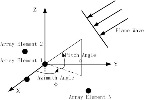
FIGURE 1. Schematic diagram of antenna array and incident signal.
Assuming that the spoofing signals all come from one direction, the form of the signals received by the navigation receiver antenna array can be expressed as:
where,
where,
In the research of this paper, in order to facilitate the analysis, only the scene where a single real satellite signal and a repeater spoofing signal exist, the received signal of the array can be expressed as:
where,
Here it is defined that
When the mixed signal enters the antenna array, the antenna array will generate a set of array weights
Among them, the form of the direct repeater spoofing output signal is:
3 Representation of weight vector under limited number of snapshots
The minimum variance distortion-free response beamformer (MVDR) criterion is that the gain in the desired signal direction is constrained to be 1, and the array output power is minimized. The weight vector of the MVDR beamformer is the solution of the following problem:
where,
where
where
Eq. 13 can be written in the following form:
where,
Inverting
Similarly, inverting
Bringing the above formula into Eq. 12, the expression of the MVDR weight under the limited number of snapshots is obtained:
where,
When the number of snapshots m and the number of array elements N satisfy
The above Eq. 30 shows that the weight vector can be divided into two parts under the limited number of snapshots: the expected weight vector part (the first term on the right side of the equation) and the undesired perturbation part (the second term on the right-hand side of the equation) caused by the correlation between the spoofed signal and the real signal and the limited number of snapshots.
4 The influence of spoofing signal power on algorithm performance
4.2 The influence of the power of the spoofing on the output of the real signal
The output of the array signal processed by the MVDR algorithm is:
where,
The real signal output power is:
Because P has the following properties:
And
where
4.2 The influence of the power of the spoofing on the output of the spoofing
Direct repeater spoofing includes pure spoofing signal part and repeater noise part, since these two parts come from the same direction, the antenna array spatial processing has the same response to all signals coming from the same direction. Therefore, this paper deduces the response of the antenna array in the direction of the spoofing, so as to obtain the output power of pure spoofing and repeater noise.
First, the pure spoofing output power processed by the antenna array can be expressed as:
Therefore, the spatial response of the antenna array in the spoofing direction after weighted processing can be expressed as:
Further expansion of the above equation can be obtained:
Solving the expectation for
Since
where,
Recalling that the real signal sampling
Substitute to get:
Eq. 44 can be simplified as:
Substituting the above formula into Eq. 40, get:
Under the single-relay spoofing jammer model, the expressions for r and Q are as follows:
Eqs 47, 48 are brought into Eq. 46, and
Naturally, the powers of transponder pure spoofing
When directly repeater the spoofing jamming signal, the pure spoofing and the repeater noise always maintain the SNR before repeater, denoted as
When the spoofing-to-signal ratio (SSR) is low, namely
It can be seen intuitively that with the increase of SSR, the power of output repeater pure spoofing and repeater noise always decreases. When the SSR is high, namely
It can be seen from the above formula that when the repeater deception signal delays the real signal larger,
This shows that the MVDR algorithm has a strong suppression effect on the direct-relay spoofing signal, so that the receiver can keep the state of receiving the real signal. According to the limit approximation results of the equation at high and low SSR, it can be seen that the overall change trend of the output power of the spoofing signal is to decrease at first, when the delay is small and the correlation is large, it will eventually tend to a stable value, and when there is no correlation, the power of the spoofing signal will continue to decrease. In the next section, simulation verification is carried out to further analyze the correctness of the equation and the suppression performance of MVDR in direct repeater spoofing.
5 Analysis of simulation results
5.1 Simulation of signal flow
In order to verify the analysis results in the previous section and gain a deeper understanding of the anti-spoofing performance of the MVDR algorithm, this paper compares the data simulation results and theoretical analysis in this section. The expectation operator was replaced with the sample mean of 200 Monte Carlo runs, each consisting of 40,000 data samples.
Two sets of simulation scenarios are set up, and the parameters are shown in Table 1. The antenna array is the 7-element central circular array shown in Figure 2, and the array element spacing is half wavelength.
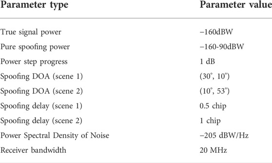
TABLE 1. Public parameter settings.
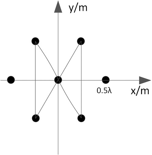
FIGURE 2. Schematic diagram of the arrangement of antenna array elements.
Under the above signal settings, the correlation coefficients
In the experiment, the output power of real signal, repeater pure spoofing and repeater noise are simulated respectively with the change of the SSR. The SSR gradually increases from 0 to 70 dB at intervals of 1 dB. The results are shown in Figures 3–5 below:
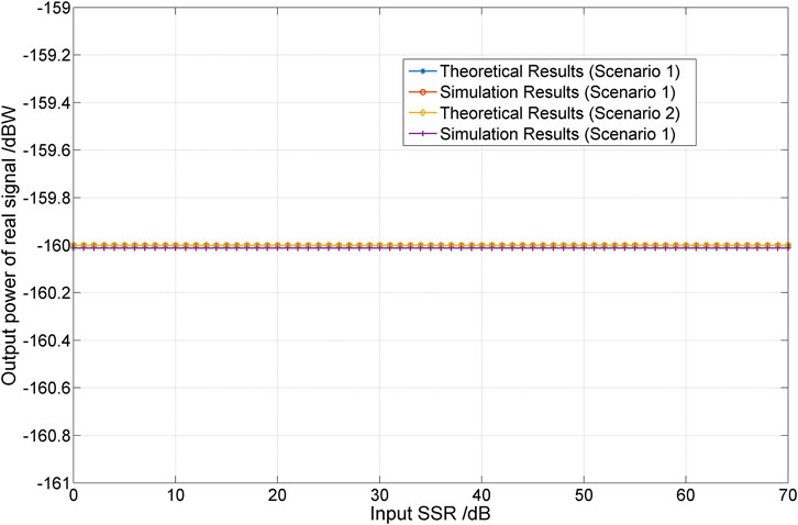
FIGURE 3. The output real signal power varies with SSR.
Figure 3 demonstrates that the true signal power remains constant throughout, the simulation results in Figure 4 and Figure 5 are consistent with the theoretical analysis, and the power always maintains a downward trend. In order to analyze the specific impact of the MVDR algorithm on the anti-spoofing performance of the navigation receiver, this paper gives the change of the carrier-to-noise ratio (CNR) of the receiver’s output navigation signal and repeater spoofing with the input spoofing ratio. The results are shown in Figure 6 below:
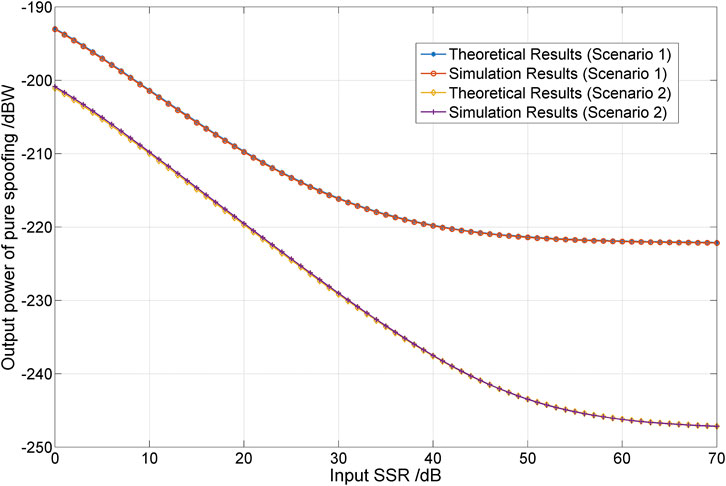
FIGURE 4. The output repeater pure spoofing power varies with SSR.
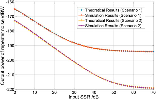
FIGURE 5. The output repeater noise power varies with SSR.
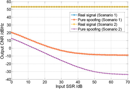
FIGURE 6. The output CNR varies with SSR.
The beam patterns at 0dB and 70 dB SSR in Scenario 1 are given below:
Through the simulation in this scenario, it can be seen that the simulation results and the theoretical analysis curves are very close. It can be seen from Figure 3 that, for the real signal, the output power has nothing to do with the SSR, and is always close to the real input signal power. For the repeater spoofing signal, in Figures 4, 5, the powers of repeater spoofing and noise both show a decreasing trend in both scenarios, and in this scenario, the output power of repeater noise is less than the real signal when the SSR is 0 dB output power, as can be seen from Figure 7, the antenna array in scenario 1 forms a nulling of about 33 dB in the spoofing signal, which is consistent with the theory. At this time, the power of repeater spoofing is about 30 dB lower than the real signal level, which cannot pose a spoofing threat to the receiver. After the SSR reaches 60dB, the power of repeater spoofing and repeater noise in scenario 1 is stable at about -222dBW and -194dBW, respectively, and the power of repeater spoofing and repeater noise in scenario 2 is stable at around -247dBW and -219dBW, respectively. Figure 8 shows that when the SSR is 70dB, the nulling depth of the antenna array in the spoofing direction in Scenario 1 is -132.2 dB. At this time, the values of Eqs 54, 55 are:

FIGURE 7. MVDR beam pattern at 0 dB SSR (Scenario 1).
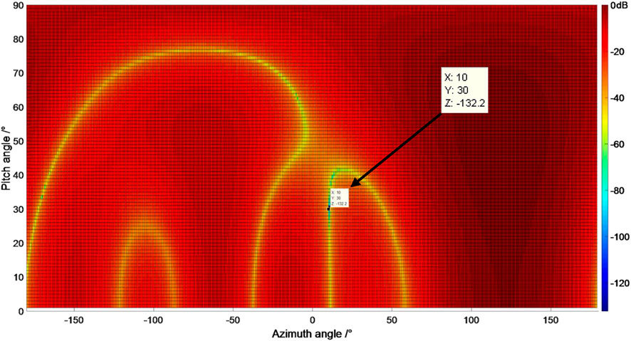
FIGURE 8. MVDR beam pattern at 70 dB SSR (Scenario 1).
The theoretical calculation and simulation results in the two scenarios are consistent, which proves that the theoretical analysis and simplification results in the previous section are correct.
Figure 6 compares the CNR of the real and spoofing signals, and it can be seen more intuitively that the CNR of repeater spoofing is always below the level of the real signal. The above results show that the total signal power of the direct-relay spoofing signal processed by the MVDR algorithm is suppressed below the real signal level, and the direct-relay spoofing signal cannot successfully deceive the MVDR anti-jamming antenna array receiver, and the power of the repeater spoofing signal cannot be successfully deceived. The stronger it is, the better the suppression effect of the MVDR antenna array is.
5.2 Simulation of multi-beam receiver
In order to verify whether the above conclusion holds when the GNSS receiver processes real satellite signals, in this section, synthetic signals of four GPS satellites with prn numbers 1, 2, 3, and 4 are generated and verified by the multi-beam software receiver processing.
The parameter settings of the four synthetic GPS satellite signals are shown in Table 2, and the parameter settings of the spoofing signals are shown in Table 3, the repeated 4 satellite signals are all set to be delayed by 1 chip, and the SSR is from 0dB to 50 dB in steps of 5dB, all from one direction. The parameter settings of the multi-beam software receiver are shown in Table 4, and the antenna array settings are as above. After processing by the MVDR algorithm, the changes of the code phase and of the four satellites are shown in Figure 9 and Figure 10.
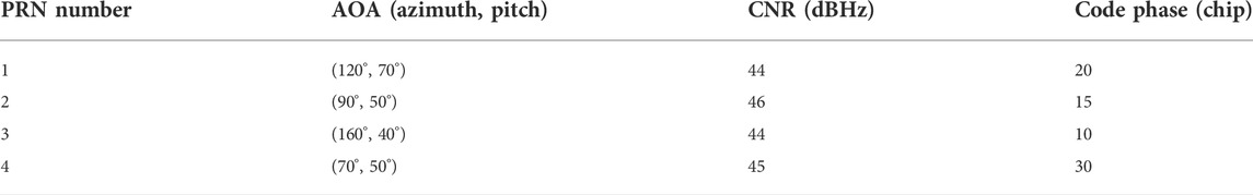
TABLE 2. Real satellite signal parameter settings.
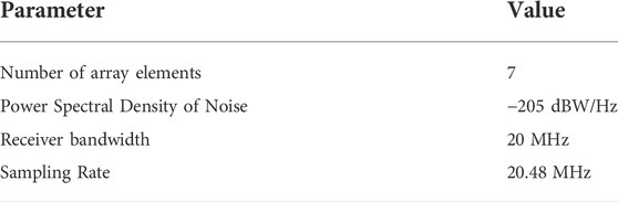
TABLE 3. Parameter setting of multi-beam receiver.
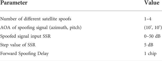
TABLE 4. Spoofing satellite signal parameter settings.
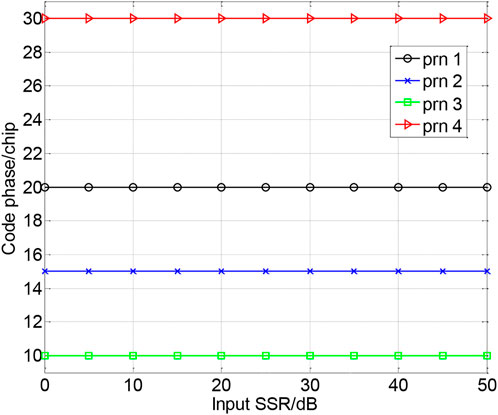
FIGURE 9. The code phase varies with SSR.
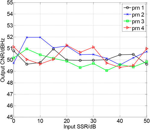
FIGURE 10. The CNR varies with SSR.
As can be seen from the above figure, after processing by the MVDR algorithm, the code phases captured by the receiver are all the code phases of the synthetic GPS satellite signals. Due to the gain of the array processing, the CNR of the received signal increases by about 6dB, and keep it floating in a small range. This verifies that a single incoming direct-relay spoofing signal cannot spoof the MVDR anti-jamming antenna array receiver, and the MVDR algorithm has no effect on the power of the real signal.
6 Conclusion
This paper analyzes the anti-direct repeater spoofing performance of the MVDR algorithm in the navigation system, and deduces the expression of the power of the real signal, the spoofing signal and the repeater noise processed by the MVDR algorithm with the power of the input spoofing signal, the anti-spoofing performance of the MVDR algorithm is quantitatively measured according to the two indicators of output signal power and CNR. Through derivation and analysis, it is found that the power of the repeater spoofing part in the direct repeater spoofing signal processed by the MVDR algorithm is always much smaller than the real signal power.
This shows that the direct repeater spoofing cannot counteract the threat of jamming antenna array receivers, and simulations are used to verify the correctness of the conclusions. This paper theoretically clarifies that the MVDR algorithm still has good anti-spoofing ability in the navigation system, which provides theoretical support for the anti-spoofing of the antenna array, and also provides assistance for the processing of the back-end signal and information level. The implementation of anti-spoofing has important guiding significance.
Data availability statement
The raw data supporting the conclusions of this article will be made available by the authors, without undue reservation.
Author contributions
Conceptualization: SN and BR; methodology and validation: BR and FC; formal analysis and investigation: ZL and CH; resources: SH and FC; writing-original draft preparation: SN; writing-review and editing: BR and ZL; supervision: BR and FC.
Funding
This research was funded by the National Natural Science Foundation of China (62003354 and U20A0193).
Acknowledgments
The authors would like to thank the College of Electronic Sciences for providing the test platform.
Conflict of interest
The authors declare that the research was conducted in the absence of any commercial or financial relationships that could be construed as a potential conflict of interest.
Publisher’s note
All claims expressed in this article are solely those of the authors and do not necessarily represent those of their affiliated organizations, or those of the publisher, the editors and the reviewers. Any product that may be evaluated in this article, or claim that may be made by its manufacturer, is not guaranteed or endorsed by the publisher.
References
1. Liu J, Gao K, Guo W, Cui J, Guo C. Role, path, and vision of “5G + BDS/GNSS”. Satell Navig (2020) 1:23–8. doi:10.1186/s43020-020-00024-w
2. Ma L, You Z, Liu T, Shi S. Coupled integration of CSAC, MIMU, and GNSS for improved PNT performance. Sensors (2016) 16:682. doi:10.3390/s16050682
3. Ma L, You Z, Li B, Zhou B, Han R. Deep coupled integration of CSAC and GNSS for robust PNT. Sensors (2015) 15:23050–70. doi:10.3390/s150923050
4. Hein G. Status, perspectives and trends of satellite navigation. Satell Navig (2020) 1:22. doi:10.1186/s43020-020-00023-x
5. Song J, Lu Z, Xiao Z, Li B, Sun G. Optimal order of time-domain adaptive filter for anti-jamming navigation receiver. Remote Sens (Basel) (2022) 14:48. doi:10.3390/rs14010048
6. Lu Z, Song J, Huang L, Ren C, Xiao Z, Li B. Distortionless 1/2 overlap windowing in frequency domain anti-jamming of satellite navigation receivers. Remote Sens (Basel) (2022) 14:1801. doi:10.3390/rs14081801
7. Lu Z, Nie J, Wan Y, Ou G. Optimal reference element for interference suppression in GNSS antenna arrays under channel mismatch. IET Radar Sonar & Navigation (2017) 11:1161–9. doi:10.1049/iet-rsn.2016.0582
8. Huang L, Lu Z, Xiao Z, Ren C, Song J, Li B. Suppression of jammer multipath in GNSS antenna array receiver. Remote Sens (Basel) (2022) 14:350. doi:10.3390/rs14020350
9. Daneshmand S, Jafarnia-Jahromi A, Broumandan A. A GNSS structural interference mitigation technique using antenna array processing. In: 2014 IEEE 8th Sensor Array and Multichannel Signal Processing Workshop (SAM); 2014 Aug 25; Spain (2014). p. 109–12.
10. Behar V, Kabakchiev C. Multiple signal extraction in jamming using Adaptive Beamforming with arbitrary array configurations. Cybern Inf Technol (2009) 9:76–85. https://www.researchgate.net/publication/229008324
11. Happy L, Van T. Optimal array processing technology. Beijing: Tsinghua University Press (2008). p. 324–6.
12. Liao B, Madanayake A, Agathoklis P. Array signal processing and systems. Multidimens Syst Signal Process (2018) 29:467–73. doi:10.1007/s11045-018-0555-7
13. Lu Z, Nie J, Chen F, Chen H, Ou G. Adaptive time taps of STAP under channel mismatch for GNSS antenna arrays. IEEE Trans Instrum Meas (2017) 66:2813–24. doi:10.1109/TIM.2017.2728420
14. Han J, Park H, Kim B. Simulink model implementation of MVDR adaptive beamformer for GPS anti-jamming. Journal of positioning. Navigation, and Timing (2020) 9:51–7. doi:10.11003/JPNT.2020.9.2.51
15. Dai X, Nie J, Chen F, Ou G. Distortionless space-time adaptive processor based on MVDR beamformer for GNSS receiver. IET Radar Sonar & Navigation (2017) 11:1488–94. doi:10.1049/iet-rsn.2017.0168
16. Liu G, Sun H, Jin D. Experimental research of vector hydrophone MVDR algorithm. J Inf Comput Sci (2015) 12:1329–36. doi:10.12733/jics20105550
17. Chen J, Chen X, Zhang H, Zhang K, Liu Q. Suppression method for main-lobe interrupted sampling repeater jamming in distributed radar. IEEE Access (2020) 8:139255–65. doi:10.1109/ACCESS.2020.3000278
18. Hao C, Liu Y, Wang X, Sun X. A modified anti-jamming method using dual-polarized ellipsoid minimum variance distortionless response to predict the coverage ratio of global positioning system signal. IEEE Sens J (2021) 21:26839–47. doi:10.1109/JSEN.2021.3121492
19. Jia Q, Wu R, Wang W, Lu D, Wang L. Adaptive blind anti-jamming algorithm using acquisition information to reduce the carrier phase bias. GPS Solut (2018) 22:99–12. doi:10.1007/s10291-018-0764-4
20. Chen F, Nie J, Yong L. A two-stage anti-jamming algorithm for GNSS antenna array. J Natl Univ Defense Tech (2015) 37:43752. doi:10.11887/j.cn.201503002
21. Wei C, Liu J, Zhang F, Liu P. The comparison of two adaptive anti-jamming algorithm of navigation receiver. Lecture Notes Electr Eng (2012) 161:591–600. doi:10.1007/978-3-642-29193-7_56
22. Zhang L, Huang L, Li B, Huang M, Yin J, Bao W. Fast-moving jamming suppression for uav navigation: A minimum dispersion distortionless response beamforming approach. IEEE Trans Veh Technol (2019) 68:7815–27. doi:10.1109/TVT.2019.2924951
23. Nagaraju V, Sethy A, Boddu RSK, Balambigai S, Sakthisudhan K. Diagnosed image of breast cancer by antenna MVDR beamforming algorithm with composites. Mater Today Proc (2021) 46:4207–11. doi:10.1016/j.matpr.2021.03.029
24. He B, Su H. Game theoretic countermeasure analysis for multistatic radars and multiple jammers. Radio Sci (2021) 56:1–14. doi:10.1029/2020RS007202
25. Ni S, Ren B, Chen F, Lu Z, Wang J, Ma P, et al. GNSS Spoofing suppression based on multi-satellite and multi-channel array processing. Front Phys (2022) 10. in press. doi:10.3389/fphy.2022.905918
26. Lu Z, Chen H, Chen F, Nie J, Ou G. Blind adaptive channel mismatch equalisation method for GNSS antenna arrays. IET Radar Sonar & Navigation (2018) 12:383–9. doi:10.1049/iet-rsn.2017.0416
27. Huang Q, Zhang L, Fang Y. Performance analysis of Low-complexity MVDR beamformer in spherical harmonics domain. Signal Process. (2018) 153:153–63. doi:10.1016/j.sigpro.2018.07.016
28. Amin-Nejad S, Gashteroodkhani T, Basharkhah K. A comparison of MVDR and LCMV beamformers' floating point implementations on FPGAs. Wirel Pers Commun (2018) 98:1913–29. doi:10.1007/s11277-017-4953-1
29. Thotla V, Zawodniok M. Detection of multiple R/C devices using MVDR and genetic algorithms. IEEE Trans Instrum Meas (2015) 64:2821–8. doi:10.1109/TIM.2015.2415112
30. Behar V, Kabakchiev C, Rohling H. MVDR radar signal processing approach for jamming suppression in satellite navigation receivers. In: 11-th International Radar Symposium; 2010 Jun 16-18; Vilnius, Lithuania (2002). p. 1–4.
31. Zoltowski M. On the performance analysis of the MVDR beamformer in the presence of correlated interference. IEEE Trans Acoust (1988) 36:945–7. doi:10.1109/29.1614
32. Pan C, Chen J, Benesty J. Performance study of the MVDR beamformer as a function of the source incidence angle. Ieee/acm Trans Audio Speech Lang Process (2014) 22:67–79. doi:10.1109/TASL.2013.2283104
33. Wax M, Anu Y. Performance analysis of the minimum variance beamformer. IEEE Trans Signal Process (1996) 44(4):928–37. doi:10.1109/78.492545
34. Xie L, He Z, Tong J. Cross-validated tuning of shrinkage factors for MVDR beamforming based on regularized covariance matrix estimation. Electr Eng Syst Sci (2021). [Preprint]. doi:10.48550/arXiv.2104.01909
35. Huang Y, Zhou M, Vorobyov S. New designs on MVDR robust adaptive beamforming based on optimal steering vector estimation. IEEE Trans Signal Process (2019) 67:3624–3638. doi:10.1109/TSP.2019.2918997
36. Shahab S, Zainun A. MVDR algorithm based linear antenna array performance assessment for adaptive beamforming application. J Eng Sci Tech (2017) 12:1366–85.
37. Reddy V, Paulraj A, Kailath T. Performance analysis of the optimum beamformer in the presence of correlated sources and its behavior under spatial smoothing. IEEE Trans Acoust (1987) 35:927–36. doi:10.1109/TASSP.1987.1165239
38. Yazdi N, Todros K. Measure-transformed MVDR beamforming. IEEE Signal Process Lett (2020) 27:1959–63. doi:10.1109/LSP.2020.3032287
39. Meng W, Ke Y, Li J, Zheng C, Li X. Finite data performance analysis of one-bit MVDR and phase-only MVDR. Signal Process. (2021) 184:108018. doi:10.1016/j.sigpro.2021.108018
40. Shahab S, Zainun A, Noordin N, Ibrahim I. Performance comparison of nature-inspired optimization algorithms applied to MVDR technique for canceling multiple access interference signals. Indian J Sci Technol (2018) 11 11–20. doi:10.17485/ijst/2018/v11i3/92398
41. Liu J, Liu W, Liu H, Zhang ZJ, Chen B. Performance of the SMI beamformer with signal steering vector errors in heterogeneous environments. Signal Process. (2016) 123:22–9. doi:10.1016/j.sigpro.2015.12.011
42. Liu J, Orlando D, Liu W. SINR distribution for the persymmetric SMI beamformer with steering vector mismatches. IEEE Trans Signal Process (2019) 67:1382–92. doi:10.1109/tsp.2019.2892027
43. Chen Y, Lee J. Finite data performance analysis of MVDR antenna array beamformers with diagonal loading. Prog Electromagnetics Res (2013) 134:475–507. doi:10.2528/PIER12092006
44. Tabra Y, Sabbar B. Hybrid MVDR-LMS beamforming for massive MIMO. Indonesian J Electr Eng Comp Sci (2019) 16:715–23. doi:10.11591/ijeecs.v16.i2.pp715-723
Keywords: GNSS, the direct repeater spoofing, MVDR, spoofing suppression, multi-beam antijamming receiver
Citation: Ren B, Chen F, Ni S, Han C, Lu Z and Han S (2022) Performance analysis of repeater spoofing suppression based on GNSS multi-beam receiver. Front. Phys. 10:970132. doi: 10.3389/fphy.2022.970132
Received: 15 June 2022; Accepted: 28 July 2022;
Published: 22 August 2022.
Edited by:
Jaroslav Chum, Institute of Atmospheric Physics (ASCR), CzechiaReviewed by:
Jaroslav Urbář, Istituto Nazionale di Geofisica e Vulcanologia (INGV), ItalySampad Kumar Panda, K L University, India
Copyright © 2022 Ren, Chen, Ni, Han, Lu and Han. This is an open-access article distributed under the terms of the Creative Commons Attribution License (CC BY). The use, distribution or reproduction in other forums is permitted, provided the original author(s) and the copyright owner(s) are credited and that the original publication in this journal is cited, in accordance with accepted academic practice. No use, distribution or reproduction is permitted which does not comply with these terms.
*Correspondence: Shaojie Ni, nishaojie@nudt.edu.cn