Design of a vacuum system for space active hydrogen maser
 Haohui Que1,2
  Wujiabei Xu1,2 Qi Li1,2 Jie Xiang3 Tao Lu3 Tiexin Liu2
  Yong Cai2
  Jiayu Dai2* Xueling Hou1*
- 1School of Materials Science and Engineering, Shanghai University, Shanghai, China
- 2Laboratory of Time and Frequency Technology Research, Shanghai Astronomical Observatory, Chinese Academy of Sciences, Shanghai, China
- 3Shanghai Kingv Material Technology Co., Ltd, Shanghai, China
With the high precision and stability of its frequency signal outputs, active hydrogen maser plays an important role in such fields as timing, satellite navigation, and communication. However, it needs to be lighter so as to be applied in space. We made a research, based on the calculation of the hydrogen flow and the adsorption efficiency of the adsorption unit, on the parameters of the vacuum system and the structural requirements, and designed a combined vacuum pump for the Space Active Hydrogen Maser (SAHM). This vacuum pump consists of a getter pump and a small ion pump, the total mass of which is about 5 kg. The pumping speed will be about 474 L/s by computation, when an amount, 2.5 MPa L, of hydrogen has been adsorbed by getters. Theoretically, the total source hydrogen inflow in lifetime is not higher than 20% of the total capacity getter pump, thus the design should amply meet the requirements of the SAHM vacuum system, and is of great significance for future SAHM applications.
1 Introduction
The hydrogen maser, which uses the hyperfine energy level transition signal of the hydrogen atoms for precise timing, has excellent measurement accuracy and stability. It has developed rapidly since the advent of the first hydrogen maser in 1960 [1]. Many companies and organizations, such as Chinese Shanghai Observatory, Beijing Institute of Radio Metrology and Measurement, American Symmetricomg Company, Switzerland Spectratime, T4Science Company, Russia KVARZ, Vremya-CH Company and the Russian-British joint venture Quartzlock Company, have offered various kinds of high-performance hydrogen maser products which were widely applied in timing, navigation, communications, space exploration and other fields [2–5].
With the continuous development of space science experimental projects, new requirements are put forward for hydrogen masers applied in space. It not only needs better frequency stability and reliability, but also needs to meet the requirements of space applications such as light weight, small size and low power consumption. The performance of the active hydrogen maser is better than that of the passive hydrogen maser, thus the before is a better choice for the frequency standard in space. However, it is currently too bulky to be applied in space.
At present, the countries that carry out the research and development of space active hydrogen masers mainly include Europe [5–8], Russia [9–11], and China [12–14]. The Neuchatel Observatory in Switzerland used a high-Q sapphire microwave resonator to replace the traditional resonator in space active hydrogen maser, which greatly reduced the mass of the entire system to about 35 kg (Figure 1A), and the frequency stability could reach 1.5 × 10⁻¹³/s and 1.5 × 10⁻¹⁵/105 s [6, 7]. SpectraTime (SpT) developed a 40 kg lightweight active Space Hydrogen Maser (Figure 1B) for the European Space Atomic Clock Ensemble in Space (ACES) mission which would be flown on the International Space Station (ISS) in 2013 [5]. The Russian Vremya-CH company uses a glass-ceramic resonator to reduce the total mass of the active hydrogen maser to 60 kg. It could achieve a long-term stability 2 × 10–14/day, and was launched in 2011 [10, 11]. Beijing Institute of Radio Metrology and Measurement has also developed a space active hydrogen maser with a mass of about 45 kg, its stability could reach 2.3 × 10⁻¹⁵/day and might be launched with satellites in 2022. Meanwhile, it is still continuing to optimize its performance, and it will be applied in Chinese space station projects in the future [13].
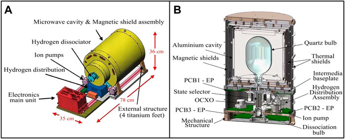
FIGURE 1. 35 kg space active hydrogen maser (A); 40 kg space active hydrogen maser (B).
The space hydrogen maser has high requirements on vacuum system, generally about 10–5 Pa [15]. The poor vacuum environment will lead to broadening of transition spectral lines and weakening of signals, which will significantly affect the overall performance. Therefore, a vacuum system that can maintain working conditions for a long time is particularly important. As a comparison, the ground active hydrogen maser uses a sputtering ion pump, equipped with two large magnets of about 50 kg, to maintain the vacuum state of the system. This type of vacuum pump has good stability, high reliability and long service life, whereas it is so bulky that cannot be used in SAHM.
The spaceborne passive hydrogen maser adopts a scheme of combined pump system to meet the vacuum requirements of space applications [16]. The combined pump consists of a getter pump and a small ion pump, in which the getter pump mainly absorbs reactive gases (mainly hydrogen), and the ion pump absorbs the inert gas in the system. This type of combined pump system turned out to have the high stability and reliability, the large capacity and particularly the small volume and light mass while, which is very consistent with the development trend of the hydrogen maser. Compared with the passive hydrogen maser, the active ones have better stability and accuracy. However, the active hydrogen maser also has larger hydrogen load flow rate, for which the vacuum system needs to be redesigned to meet the needs of the space active hydrogen maser.
Space active hydrogen masers are mainly used for space station punctuality, space high-precision scientific experiments and large scientific installations such as space telescopes and space VLBI (Very Long Baseline Interferometry) projects. Active hydrogen maser has not yet had space applications in China. The Shanghai Astronomical Observatory Space VLBI Project requires higher time-frequency accuracy and stability, which promotes the space application process of active hydrogen masers.
This work aims to design a lightweight vacuum combined pump for space application of active hydrogen masers. The combined pump combines a zirconium iron vanadium alloy getter pump and a small ion pump, with a total mass of about 5 kg, which is 90% lighter than that of the ground active hydrogen masers. In terms of performance, the theoretical pumping rate and total pumping volume of the design’s 10-year service period (according to the requirements of the national research task) far exceeded the expectations, which reflect the excellent gas adsorption and vacuum retention capabilities. This design amply satisfies the vacuum degree and life requirements of the vacuum system, and provides significant reference for the active hydrogen maser application in space.
2 Theory and method
2.1 Vacuum system of hydrogen maser
Figure 2 shows the basic physical structure of the hydrogen maser. After purification, ionization, and state selection, the hydrogen gas enters the storage bubble, where the energy level transition occurs and a microwave signal of a specific frequency is generated. Finally, it will be collected by the vacuum pump. The storage time of hydrogen atoms in the atomic storage bubble is about 1 s. In order to avoid collisions between high-energy hydrogen atoms (
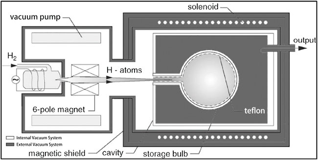
FIGURE 2. Basic structure of the physical part of the hydrogen maser.
In a high vacuum environment, the particle density in the atomic storage bubble is at a low level, which increases the average free path of high-energy hydrogen atoms, and reduces the collision probability between hydrogen atoms or with other particles, thereby prolonging their interaction time. At present, the space hydrogen maser mainly adopts a double vacuum system [17]. The background vacuum degree of the internal vacuum system during operation is about 10–5 Pa. The stable system vacuum degree is one of the important influence factors affecting the long-term stability of the hydrogen maser. The vacuum pump system turns out to be the most critical part that affects the vacuum degree of hydrogen masers.
2.2 Basic parameters of hydrogen maser vacuum system
2.2.1 Gas flow
The temperature is almost constant in the vacuum system of hydrogen maser. According to The Boyle’s law, the product of the gas volume
The pressure everywhere remains generally constant when the system is stable, and the pressure changes little in a short time interval. At this time, Formula 1 can be written as:
This is the constant pressure expression of flow, unit for Pa⋅m3⋅s−1 or Pa⋅m3⋅s−1.
2.2.2 Pumping rate
Figure 3 is a brief schematic diagram of the vacuum system. When the vacuum pump starts pumping, the pressure
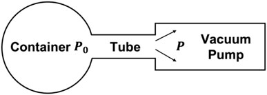
FIGURE 3. Brief schematic diagram of vacuum system.
The unit is m3⋅s−1 or L⋅s−1. Compared with Formula 2, when the pressure
Due to the pressure difference between the pumped container and the vacuum pump, there is also a difference between the pumping rate of the vacuum pump and the pumping rate of the gas in the container. To distinguish between them, the pumping speed of the gas in the container is usually called the effective pumping speed, represented by
2.2.3 Flow conductance
Hydrogen pressure and flow rate are both small while in the high vacuum state of the hydrogen maser, which make the probability of collision between molecules is much less than with the tube wall. After each collision, molecules will move forward or backward in different directions. Therefore, the flow of hydrogen in the connecting tube is molecular flow.
The calculation of flow conductance is closely related to the shape of the tube. The structure of hydrogen maser is very compact, and short tubes (tube length
Where the α is the Clausing coefficient, which is related to the value of
The conversion formula for flow conductance at different temperatures is:
Based on Formulas 5ormulas –Formulas 7, we can obtain the relationship between the flow conductance of hydrogen in the short tube and the temperature:
2.2.4 Basic equation of vacuum system
When the gas flows in the tube, the pressure decreases gradually along the direction of the gas flow, so there is a dynamic pressure difference
In the vacuum system, assuming that there is no air leakage or air source and the air flow is in a stable state, according to the law of conservation of mass, the flow
After the convention of Formula 11, the following equation can be obtained:
Formula 12 is the basic equation of the vacuum system when the air flow reaches a stable state. It relates the flow conductance
2.2.5 Effective suction area
As the absorption of hydrogen content in the getter increases, hydrogen atoms at the surface will spread inward at a slower rate, which results in a reduced inspiratory rate. In order to ensure that the suction rate can maintain a good vacuum state of the system after absorbing a certain amount of gas during the required working life, it is necessary to ensure a certain effective suction area. The calculation formula of the effective suction area is as follows:
Where the
2.2.6 Hydrogen evolution flow
The hydrogen evolution flow rate in hydrogen maser is mainly determined by the nickel tube purifier. We designed a measuring device for hydrogen permeability under different operating currents of nickel tube purifier. As shown in Figure 4A, it is mainly composed of nickel tube purifier, electrode flange, thermostatic circuit board and measuring tube. The right side of the measuring tube is connected with a vacuum pump to maintain the vacuum environment of measuring. The measuring principle is described as follows.
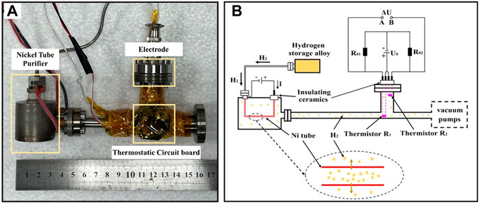
FIGURE 4. Hydrogen flow measurement experimental device (A); hydrogen flow measurement experimental principle diagram (B).
Under certain conditions, the heat conduction capacity of gas molecules is related to the number of gas molecules per unit volume. According to this principle, hydrogen is released from the hydrogen storage alloy bottle into the nickel tube; when the nickel tube is connected to the direct current, the joule temperature rises, and hydrogen diffuses outward into the measuring tube, where the heat exchange with the thermistor and changes the thermistor temperature. The temperature of thermistor corresponds to the resistance value, thus the voltage difference
In Figure 4B,
Where the
Where the
3 Design and discussion
3.1 Requirements of vacuum system design
In the vacuum system of hydrogen maser, the nickel tube purifier continuously permeates hydrogen into the system, and the vacuum state of the container needs to be maintained by the vacuum pump, which belongs to the dynamic vacuum system. In normal operation, the vacuum degree of the system should be kept at about 10–5 Pa, and the working life should be more than 10 years. Based on these two requirements, we calculate the required performance parameters of the vacuum pump design in the vacuum system.
3.1.1 Calculation of gas flow
In a vacuum system, the suction capacity and suction rate are the two most important parameters. In order to calculate the specific values of these two parameters, the total gas flow
Where,
According to the hydrogen evolution rate experiment of the nickel purifier under different current (in Section 2.2.6), the result (shown in Figure 5) shows that the hydrogen permeability increases with the increase of the working current of the nickel tube purifier. When
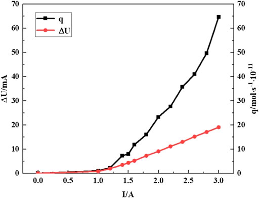
FIGURE 5. Relation curve of operating current of nickel tube and
Based on the hydrogen permeation amount
3.1.2 Calculation of conduit conductivity
In the vacuum system, it is a cylindrical stainless-steel tube between the pumped container and the vacuum pump, which is 70 mm in length and 60 mm in diameter. The cross-sectional area
3.1.3 Calculation of pumping rate
According to the requirement of hydrogen maser vacuum system, the gas pressure in the pumped container
According to effective pumping rate
Due to the short and large diameter of the tube, the change of gas pressure at both ends is very small, thus the calculated values of
3.1.4 Calculation of effective suction area
In this work, Zr-V-Fe alloy getter tablets (as shown in Figure 6) is used as the basic material of the getter pump. At the beginning of the operation, there is little internal hydrogen content and the getter tablet has a high pumping rate of hydrogen. With the increase of suction volume, the pumping rate decreases gradually. Under 20° Cand 10–5 Pa vacuum, the initial inspiration rate of the carrier is over 2,500 cm3
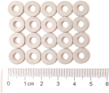
FIGURE 6. Getter tablets of vacuum pump.
The inner diameter of the single getter tablet is 4.0 mm, the outer diameter is 10.0 mm, the thickness is 1.3 mm, and the mass is 273.8 mg. The calculated effective suction surface area (the upper, lower and outer wall surfaces) of the single tablet is 172.9 mm2. Therefore, the mass of getter per unit area
According to the one-time inspiratory volume requirement,
3.2 Design of getter pump
In the design of getter pump, the main considerations are the suction amount and suction speed. The suction amount is to ensure that the working life of the getter can meet the required number of years after one activation, and the suction rate is to ensure that the getter can maintain the vacuum state requirements until the whole service life. Generally, the more the amount of getter in the pump, the larger the maximum suction amount and suction rate will be. However, its mass and volume are limited for the space hydrogen maser, thus it is necessary to combine the actual situation to calculate the proper amount of getter and get the corresponding getter pump structure design.
3.2.1 Performance design of getter pump
According to the previous calculation, the total inspiratory
Considering the balance of cost, performance, weight and allowance reserve, we design a vacuum system for space active hydrogen maser based on the above research and calculations. The pump contains 527 g getter materials with a total number of 1925 getters. The single effective suction surface area is 172.9 mm2 and the total effective suction area of about 3.3 × 105 mm2.
The inspiratory capacity of single tablet is not less than 5,000 Pa⋅L⋅g−1, thus the capacity of the total getter pump is not less than 2.5 MPa⋅L, meanwhile, the suction rate is about 474 L/s, and the theoretical gas consumption is less than 20% of the full capacity, which fully meets the above performance requirements and can meet the engineering application needs of space active hydrogen maser for more than 10 years.
3.2.2 Structural design of getter pump
Based on the performance requirements and our previous work [19], the getter pump structure designed as follows.
The overall structure of the getter pump is shown in Figure 7A, which is mainly composed of a shell, getter tablet and its bracket, and heating devices. The shape of the pump and its overall size is determined by the internal requirements of the active hydrogen maser. The outer diameter is 196.0 mm, the inner diameter is 90.0 mm, and the height is 40.0 mm. The shell of the pump is composed of a Ti metal plate, which is 1.5 mm in thick, to reduce the influence of magnetic field on the performance of the hydrogen maser.
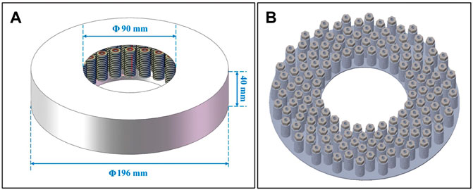
FIGURE 7. (A) External structure size of getter pump; (B) Schematic diagram of internal structure.
Figure 7B is the schematic diagram of the internal getter structure. There are altogether 175 getter units assembled in six layers, with 25 in the innermost layer and 30 in the outer five layers.
Figure 8A shows the structure of getter unit, which is mainly composed of base, getter tablets, Ti gasket, fixed nut, heating wire, and Ti support. Each getter unit contains 11 getter tablets, as described above, its inner diameter is 4.0 mm, outer diameter is 10.0 mm, thickness is 1.3 mm, and single mass is 273.8 mg (Figure 8B).
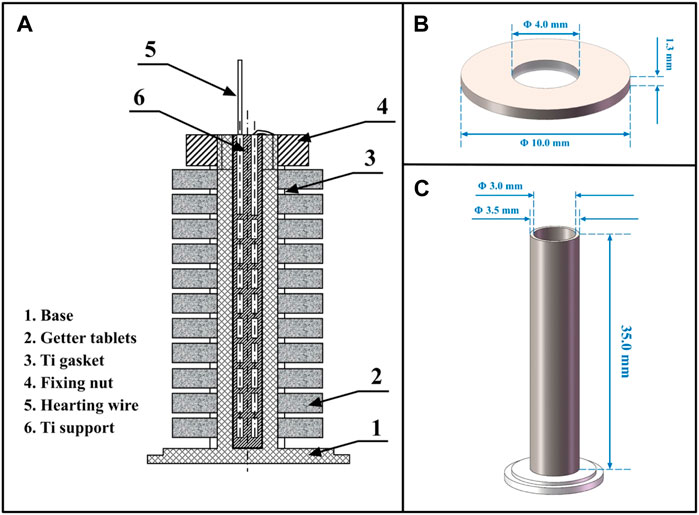
FIGURE 8. (A) Structure of getter unit; (B) Structural size of getter tablet; (C) Ti support structure size.
Each getter is separated by Ti metal gasket to increase the suction area; The bracket is a hollow structure, with an inner diameter of 3.0 mm, an outer diameter of 3.5 mm and a length of 35.0 mm (Figure 8C). Nickel-chromium alloy hot wire is installed inside the bracket to facilitate the activation of getter.
After the getter is exposed to the atmosphere or used for a long time, a passivation layer will be formed on its surface, which will reduce the rate of hydrogen absorption. Therefore, the getter pump needs to be equipped with a heating device for high temperature treatment to remove the passivation layer and obtain the fresh active surface, this process is called the getter pump activation.
The heating device uses nickel-chromium alloy heating wire with diameter of 1.0 mm and resistivity of 0.832 μΩ m. It has strong corrosion resistance, non-magnetic, and the operating temperature can up to 1,200°C. In the getter pump, the heating wires inside each getter unit are connected in series with a total length of 4.5 m and a resistance of 4.7 Ω. One end is connected with the pump shell as a negative pole, and the other end is connected with the ceramic electrode insulated with the pump shell as a positive pole. The total mass of the getter pump is approximately 4.5 kg, containing 527 g getter materials.
3.3 Lectotype of small ion pump
In the combined pump of small ion pump and getter pump, hydrogen absorption is mainly accomplished by the getter pump, and the small ion pump plays the role of eliminating trace impurities. The trace impurity gas in the vacuum system mainly comes from the gas leakage of the wall material, which is mainly determined by the outgassing rate of the wall material. As the outgassing rate decreases slowly with time during the service life, the maximum outgassing rate at the beginning is used for calculation to maximize the reliability requirements.
According to the existing data of the outgassing rate of the space-borne passive hydrogen maser [20], considering a larger hydrogen flow that the active hydrogen maser has than passive ones, we selected the Agilent 5 L/s small ion pump as the composite pump in this work. The pumping rate has a large surplus, which can be further optimized according to the requirements of practical application. Additionally, remote vacuum level monitoring can be achieved with ion pump current readings. The weight of this small ion pump is about 0.5 kg and the service life exceeds 10 h under above operating conditions [21], which fully meet the 10-year engineering application requirements.
4 Conclusion
The active hydrogen maser with excellent timing accuracy and wide amplitude stability plays an important role in the fields of timing and navigation. In order to meet the lighter requirements of the Shanghai Astronomical Observatory for SAHM in the space VLBI project, we designed a combined vacuum pump composed of a getter pump and an ion pump. The getter pump plays the main role of hydrogen adsorption. It is in the shape of a ring, with an outer diameter of 196 mm, an inner diameter of 91 mm, and a height of 40 mm. Among it there are 1,925 getter tablets, the mass of which is 527 g and the getter pump is about 4.5 kg. Agilent Diode small ion pump is adopted as the combined ion pump to deal with trace amounts of inert gas impurities. The total mass of the composite pump is about 5 kg. Under conditions with a background vacuum of 10–5 Pa for the active hydrogen maser, the effective suction area of this pump is about 3.3 × 105 mm2, which is higher than the required value (1.16 × 105 mm2). When the suction volume of the getter pump reaches 2.5 MPa⋅L, the pumping speed of is about 474 L/s, those are much higher than the total hydrogen flow rate (0.5 MPa⋅L) of the hydrogen maser life requirements for 10 years and the pumping speed requirements (more than 164 L/s), This design amply satisfies the vacuum degree and life requirements of the vacuum system, and provides significant reference for the active hydrogen maser application in space.
In order to avoid embrittlement of the aspirant material, it should be retained a certain suction margin during the 10-year operating time. Generally, there is only 10%–25% of the full capacity is used. The aspirator tablets selected in this design have not appeared embrittlement after a long period of hydrogen absorption in the engineering test, thus we set the 10-year theoretical suction capacity is at about 20% of the full capacity. The suction pump design still retains a large free space to balance the performance and mass of the vacuum system, and to ensure the adequate flow of gas in the suction pump and improve the effective contact area. If higher reliability requirements need to be met in future work, the use of aspirated tablets can be appropriately increased to increase capacity redundancy. Meanwhile, since there is no securable working data of the active hydrogen maser or other relevant data, we selected a large redundancy suction speed to make the lectotype of small ion pump, and remain a large space for lighter design, it can be further optimized after future data support. Otherwise, for verifying the adaptability and reliability of the designed combined pump in the extreme space environment, it should also be simulated in the space environment experiments, potential problems should be actively optimized to ensure the realization of all relevant functions expected.
Data availability statement
The original contributions presented in the study are included in the article/Supplementary Material, further inquiries can be directed to the corresponding authors.
Author contributions
HQ contributed majorly to this work. All authors participated in the writing of the manuscript.
Funding
This work was supported by the Joint Research Fund in Astronomy (No. U1531120) under cooperative agreement between the National Natural Science Foundation of China (NSFC) and Chinese Academy of Sciences (CAS).
Acknowledgments
We’d like to extend our sincerest acknowledgement to Professor Yiqiu Wang, who contribute to the research and improvement of the hydrogen masers in Shanghai Astronomical Observatory. Professor Wang is very kind to students, he is always patient to listen, and to help us to understand the physical principles of hydrogen maser, which is completely a complexity and not easy to us. Knowledge of the physical principle is vital to the research and design of Space Active Hydrogen Maser. The work on vacuum system for the SAHM, on the basis of the understanding of the hydrogen flux requirements, is made to ensure a stable on-board working performance, and is contributed by a series of lecturing given by Professor Wang.
Conflict of interest
Authors JX and TL were employed by Shanghai Kingv Material Technology Co., Ltd.
The remaining authors declare that the research was conducted in the absence of any commercial or financial relationships that could be construed as a potential conflict of interest.
Publisher’s note
All claims expressed in this article are solely those of the authors and do not necessarily represent those of their affiliated organizations, or those of the publisher, the editors and the reviewers. Any product that may be evaluated in this article, or claim that may be made by its manufacturer, is not guaranteed or endorsed by the publisher.
Supplementary material
The Supplementary Material for this article can be found online at: https://www.frontiersin.org/articles/10.3389/fphy.2022.970705/full#supplementary-material
References
1. Goldenberg HM, Kleppner D, Ramsey NF. Atomic hydrogen maser. Phys Rev Lett (1960) 5(8):361–2. doi:10.1103/physrevlett.5.361
2. Belyaev AA, Demidov NA, Medvedev SY, Pavlenko YK, Sakharov BA, Vorontsov VG. Russian hydrogen masers for ground and space applications. In: Paper presented at: URSI AP-RASC 2019. 2019 URSI Asia-Pacific Radio Science Conference; 2019 Mar 9-15; New Delhi, India (2019).
3. Li J, Zhang J, Bu Y, Cao C, Wang W, Zheng H. Space passive hydrogen maser a passive hydrogen maser for space applications. In: Paper presented at: IFCS 2016. 2016 IEEE International Frequency Control Symposium; 2016 May 9-12; New Orleans, LA (2016).
4. Shuai T, Xie Y. Navigation satellite on-board hydrogen atomic Clock. Ke Xue (2016) 68(54):11–5. 64. Chinese.
5. Goujon D, Rochat P, Mosset P, Boving D, Perri A, Rochat J, et al. Development of the space active hydrogen maser for the ACES mission. In: Paper presented at: EFTF 2010. 24th European Frequency and Time Forum; 2010 April 13-16; Noordwijk, Netherlands (2010).
6. Jornod A, Goujon D, Gritti D, Bernier LG. The 35 kg space active hydrogen maser (SHM-35) for ACES. In: Paper presented at: IEEE International Frequency Control Symposium and PDA Exhibition Jointly with the 17th European Frequency and Time Forum; 2003 May 4-8; Tampa, FL (2003).
7. Thieme B, Zoschg D, Baister G. Space worthy electronics package for the 35kg space active hydrogen maser on ACES. In: Paper presented at: EFTF 2004. 2004 18th European Frequency and Time Forum; 2004 Apr 5-7; Guildford, UK (2004).
8. Hess MP, Niedermaier T, Gollinger K, Helm A, Kehrer J, Ettori M, et al. Aces - getting ready. In: Paper presented at: IAC 2018. 69th International Astronautical Congress; 2018 Oct 1-5; Bremen, Germany (2018).
9. Demidov NA, Belyaev AA, Polyakov VA, Timofeev YV. Onboard hydrogen frequency standard for the millimetron space observatory. Meas Tech (2018) 61(8):791–6. doi:10.1007/s11018-018-1503-5
10. Belyaev A, Biriukov A, Demidov N, Likhacheva L, Medvedev S, Myasnikov A, et al. Russian hydrogen masers for space applications. In: Paper presented at: Proceedings of the 45th Annual Precise Time and Time Interval Systems and Applications Meeting; 2013 Dec 2-5; Bellevue, Washington (2013).
11.Vremya-CH JSC. Products VCH-1010 [internet]. Nizhny Novgorod, Russia: Vremya-CH Company (2022). Available from: https://www.vremya-ch.com/english/product/index6e49.html (Accessed May 30, 2022).
12. Zhou T, Huang J, Wu Q, Gao L. Progress of the on-board sapphire active hydrogen maser for the aces space mission of CNSA. In: Paper Presented at: IAC 2014. 65th International Astronautical Congress; 2014 Sept 29-Oct 3; Toronto, Canada (2014).
13. Wu W. Chinese independent development of active hydrogen atomic clocks will appear on the space station. Jun Min Liang Yong Ji Shu Yu Chan Pin (2017) 23:33. Chinese.
14. Wang W, Dew ITZ, Cabeza R. Age-related differences in medial temporal lobe involvement during conceptual fluency. Brain Res (2015) 2(6):48–58. Chinese. doi:10.1016/j.brainres.2014.09.061
15. Kleppner D, Berg HC, Crampton SB, Ramsey NF, Vessot RFC, Peters HE, et al. Hydrogen-Maser principles and techniques. Phys Rev (1965) 138(4A):A972–83. doi:10.1103/physrev.138.a972
16. Yang H, Dai J, Lin C. Application study of passive hydrogen maser aspirant pump. Zhen Kong Ke Xue Yu Ji Shu Xue Bao (2012) 32(4):337–40. Chinese.
17. Wang W, Zhang Y, Yang H, Zhang W. Dual vacuum active hydrogen pulse vacuum system design. Zhen Kong Ke Xue Yu Ji Shu Xue Bao (2012) 32(3):252–5. Chinese.
18. Zivanov S, Schweda H, Goujon D, Gritti D, Perruchoud G. Physics package of the 35kg space active hydrogen maser for the ACES space mission of ESA. In: Paper presented at: IEEE 2007. International Frequency Control Symposium Joint with the 21st European Frequency and Time Forum; 2007 May 29-Jun 1; Geneva, Switzerland (2007).
19. Xiang J. inventors; Shanghai Kingv Material Technology Co., Ltd, assignee. [A miniature getter pump]. Chinese patent application CN202123248351.9. Shanghai, Chinese: Shanghai Kingv Material Technology (2021).
20. Yang H. From analyzing ion pumps to improving the life of SOHM-4 hydrogen maser. Ann Shanghai Astronomical Observatory (2013) 0:64–71. Chinese.
21.Agilent Inc. Agilent ion pumps [Internet]. Santa Clara, CA: Agilent Inc (2022). Available from: https://www.agilent.com.cn/cs/library/catalogs/public/Agilent_Catalog_Ion_Pumps.pdf (Accessed May 30, 2022).
Keywords: hydrogen maser, space, active, vacuum system, getter pump, design
Citation: Que H, Xu W, Li Q, Xiang J, Lu T, Liu T, Cai Y, Dai J and Hou X (2022) Design of a vacuum system for space active hydrogen maser. Front. Phys. 10:970705. doi: 10.3389/fphy.2022.970705
Received: 16 June 2022; Accepted: 22 July 2022;
Published: 17 August 2022.
Edited by:
Jingbiao Chen, Peking University, ChinaReviewed by:
Yang Shiyu, Lanzhou institute of physics, ChinaXiumei Wang, PKU-HKUST Shenzhen-Hongkong Institution, China
Copyright © 2022 Que, Xu, Li, Xiang, Lu, Liu, Cai, Dai and Hou. This is an open-access article distributed under the terms of the Creative Commons Attribution License (CC BY). The use, distribution or reproduction in other forums is permitted, provided the original author(s) and the copyright owner(s) are credited and that the original publication in this journal is cited, in accordance with accepted academic practice. No use, distribution or reproduction is permitted which does not comply with these terms.
*Correspondence: Jiayu Dai, daijy@shao.ac.cn; Xueling Hou, flybird1656@163.com