The dynamic investigation of intrinsic vibration characteristics of a stranding machine by the finite element method
 Kai Ren
 Bo Leng1
 - 1School of Mechanical and Electronic Engineering, Nanjing Forestry University, Nanjing, China
- 2School of Mechanical Engineering, Southeast University, Nanjing, China
In response to the design problems of violent vibration and noise when a stranding machine is running at high speed, this project completed a motion simulation and vibration analysis based on the prototype FB-650C-2 bow-type stranding machine produced by Fuchuan Mechanical and Electrical Technology Co. The modal analysis was carried out in ANSYS to obtain the first eight orders of inherent frequencies and vibration patterns, combined with excitation force analysis to verify whether the rotating parts could avoid the resonant frequency when operating. Harmonic response analysis was carried out based on the modal state to calculate the steady-state forced vibration of the structure, and the variation curve of response value (usual deformation) with frequency and the cloud diagrams of stress distribution of each component at the rotation frequency were obtained. Suggestions for improving vibration and reducing noise were made based on the experimental and analytical results.
1 Introduction
Wire and cable play a very big role in promoting the economic development of China and are a basic auxiliary industry for various other industries [1]. With the rapid development of the economy and the popularity of electric vehicles, the power shortage has continued to expand, which also increases the need for wire and cable production in China. In the fabrication of wire and cable, the stranding equipment occupies a critical position [2–4] and the vibration and noise of the machine not only adversely affects the workers’ environment but also contributes to metal fatigue that reduces the performance and life of the machine components [5–7]. In the past three decades, with the continuous updating of stranding technology, domestic stranding equipment has been greatly improved; nevertheless, there is still much work to be carried out before domestic stranding machines reach leading international levels.
For modal analysis and experimental modal analysis of stranding machines, the current trend is to combine finite element methods and experimental modal analysis techniques in an organic way [8–11]. To understand the dynamic performance of the stranding machine, modal analysis of each key component as well as the whole machine is required to obtain accurate modal parameters. However, since the modal analysis alone does not reflect the influence of external excitation on the instrument under normal operation, the harmonic response analysis of the whole machine is very important [12, 13]. Modal analysis is an essential method for studying the vibration of components under working conditions. For example, the theoretical working of the buffer block was explored to investigate vibration and its effect on fatigue and performance, and the predictions showed good agreement with the experimental results [14]. Even at a nanometer scale, atomic vibration has a large influence on the overall performance of materials [15].
In this paper, a modal analysis and vibration test of the FB-650C-2 bow-type stranding machine produced by Fuchuan Mechanical and Electrical Co., Ltd were carried out to simulate the actual working condition of the machine and to determine the causes of vibration and noise. The results provide a theoretical basis for future research on ways to reduce vibration and noise without compromising productivity.
2 Materials and methods
2.1 Modal analysis theory
The bow-type stranding machine is generally used to produce small cross-section strands for making a cable. It operates at a high speed, up to 2800 rpm, and the output can reach 3–4.5 times that of a tubular stranding machine or frame stranding machine. However, the high speed of rotation of the spindle in the cantilever mechanism can easily generate strong vibration. Figure 1 provides a schematic diagram of the structure of the bow-type stranding machine.
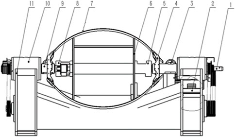
FIGURE 1. Schematic diagram of the structure of the bow-type stranding machine. (1) Incoming spindle, (2) motor base, (3) spindle guide wheel, (4) bow arm, (5) incoming disc bearing seat, (6) disc, (7) carbon fiber bow belt, (8) threading disc bearing seat, (9) outgoing spindle, (10) bearing box, and (11) base.
In the bow-type stranding machine, the whole rotating part is driven by a motor, accelerated by a synchronous pulley, up to 2000 rpm. Multi-strand copper wire from the feed spindle passes through a small hole, guided by the spindle guide wheel, bow arm, and carbon fiber bow belt. The wire is then twisted together in a certain order and at a specific distance by the circular movement of the bow and the forward movement of the machine. Then, it is passed through the relay wheel, tensioning mechanism, wire arrangement mechanism, and is finally wound on the wire tray to complete the stranding. The wire feed spindle delivers the wire to the stranding machine, and the wire enters the system through the wire feed hole at the right end of the shaft. Supported by four bearings on the bearing box, this usually suffers from violent vibration and serious heat generation during the extended high-speed rotation. The outgoing spindle, whose operating principle is roughly the same as the incoming spindle, is structurally smaller in length but larger in radius, with improved cantilevering. An electromagnetic relay is provided at one end of the spindle so that the machine can stop in time if the wire is broken to prevent ineffective stranding. The FB-650C-2 bow-type stranding machine studied in this project has a high output with lower power usage compared with domestic and foreign machines of the same specification. However, according to feedback from the cable manufacturers, the violent vibration and noise generated during operation of the machine seriously hinder development of the enterprise.
The bow-type stranding machine is a linear system with multiple degrees of freedom, and based on the principles of mechanical vibration, the differential equation of motion for a deterministic system is:
Eq. 1 is the basic equation of dynamic finite element analysis. In undamped modal analysis, the damping term in (1) can be neglected and a new differential equation of motion can be written with the external forces equal to zero, as shown in Eq. 2:
For a linear system, the solution of Eq. 2 takes the form:
where
When the structure vibrates freely, the amplitude
Eq. 5 represents a system of N algebraic equations about
2.2 Harmonic response analysis theory
In the stranding machine vibration test system, the external force generated in the operation of the system can be considered as a periodic load. The structure is loaded with a simple harmonic force consistent with the operating conditions, and the load force is brought into Formula (1) as follows:
where
For a general mechanical model, the damping at each node in the structure is different, resulting in each unit node in the structure moving at the same frequency but in different phases. The displacement expression of the structure is:
where
All the calculations in this work, including the fundamental harmonic response equations, were performed using ANSYS Workbench with three basic solution methods: the full method, the reduced method, and the modal superposition method [20–22]. The ANSYS Workbench is based on the finite element method (FEM), which is a numerical technique for solving approximate solutions of boundary value problems of partial differential equations. It uses the variational method to make the error function reach the minimum value and produce a stable solution. All the mesh types were hexahedrons in our calculations.
2.3 Generation of the finite element model of the stranding machine
The main working part of the stranding machine contains complex structures such as the incoming spindle and the outgoing spindle. First, the 3D model of the bow-shaped stranding machine was simplified, and a common node was used between the base side plate and the barrel, between the tendon plate and the bearing box, and between the supporting tendon and the barrel to convey the nodal forces and deformation displacement. The material parameters of the simplified model of the stranding machine are shown in Table 1.
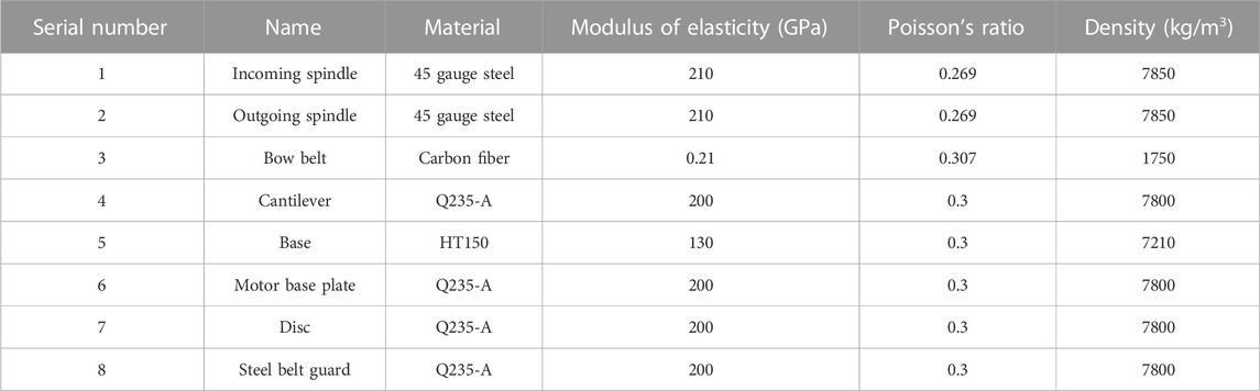
TABLE 1. Summary of material parameters.
2.4 Body meshing
In our structural model, a quadrilateral mapping division was used to control the number of meshes by taking the length of the shortest line as the reference and to minimize the calculation volume within the specified range by ensuring the calculation error. To choose a suitable degree of refinement and avoid meshes with excessive angles and deformations, the base cylinder was locally encrypted at the connection with the side plate, and the mesh was divided as shown in Figure 2, while the main shaft was separately separated for meshing, as shown in Supplementary Figure S1 in Supporting Information.
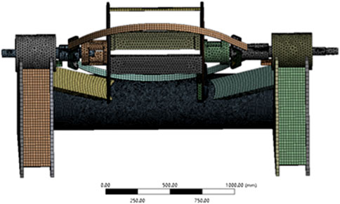
FIGURE 2. Stranding machine mesh division.
3 Results and discussion
3.1 Modal analysis results
Using the finite element model of the bow-type stranding machine that was constructed, the solution mode was set to modal analysis, the block method was adopted, and the order was set to 8. After 40,530 s of calculation, the first eight steps of the machine’s inherent frequencies and the corresponding vibration patterns were obtained. The inherent frequencies are shown in Table 2, and the corresponding vibration patterns are shown in Supplementary Figure S2.
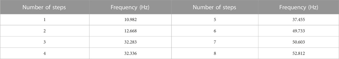
TABLE 2. Stranding machine first eighth order inherent frequency.
As can be seen in Table 2, the first eight orders of the stranding machine’s inherent frequency are concentrated between 32 and 53 Hz. Under normal operation, the stranding machine rotating part has a rotation frequency of 33.33 Hz, between the fourth- and fifth-order inherent frequencies. When the machine is in normal operation, the rotation frequency is 1 Hz different from the fourth-order inherent frequency; the motor frequency is 50 Hz, located between the sixth and seventh orders, and the sixth-order inherent frequency difference is 0.27 Hz. Thus, in normal operation at the given excitation frequency, the machine is likely to resonate.
3.2 Harmonic response analysis results
In this paper, the harmonic response analysis of the structural model of the aforementioned bow-type stranding machine was carried out using the modal superposition method to find the displacement response of the stranding machine under the action of excitation frequencies from 0 to 100 Hz. With a motor power of 11 kW and a synchronous belt acceleration system transmission ratio i = 1.37, a motor speed of 1460 rad/min can be obtained from the motor with an incoming spindle and outgoing spindle input torque of 49.42 Nm. With a spindle drive pulley of 134 mm diameter, a torsional force of 737 N can be obtained by adding the shaft’s circumferential direction as shown in Figure 3.
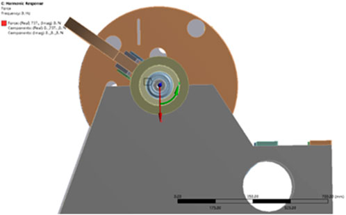
FIGURE 3. Schematic diagram of incentive addition.
Figures 4A, B show the deformation curves of the carbon fiber bow belt in turn. It can be seen that the deformation curves of the carbon fiber bow belt in the vertical y and horizontal z directions are approximately the same. In the vertical direction, a sharp increase in deformation occurs at frequencies between 34 Hz and 38 Hz and reaches a maximum of 2.38 mm at 38 Hz; in the horizontal direction, the bow belt reaches a maximum deflection of 1.705 mm at 38 Hz. The stranding machine studied in this paper operates normally at 2000 rpm (33.33 Hz) with a motor frequency of 50 Hz. From the shape of the curve, it can be seen that the horizontal and vertical displacements are relatively large at this frequency, so resonance will occur at the normal operating frequency. Figures 4C, D show the deformation of the incoming spindle in the y and z directions. The shape of the curve is similar to that of the bow belt, the deformation of the incoming spindle in the y-direction reaches its maximum at 38 Hz and the deformation amplitude is up to 0.017 mm. Smaller peaks of deformation occur at both 32 Hz and 50 Hz (Fig. 4). Figures 4E, F show the related curves of deformation and frequency of the outgoing spindles, respectively. In the vertical direction, when the excitation frequency is 38 Hz, the deformation amplitude reaches 0.019 mm and 0.093 mm in the horizontal direction. The peak value is more prominent at 32 Hz in the horizontal direction, and it can be seen that there is a large deformation of the outgoing spindle in the horizontal direction, which is most obvious when the structure resonates. In summary, it can be seen that each component resonates at 32 Hz, 38 Hz, and 50 Hz and that the deformation reaches a maximum at 38 Hz; however, the rotation frequency of this model is 33.33 Hz under normal working conditions. To combine the peak point and modal analysis, we chose to solve the stress distribution of each component at 32 Hz.
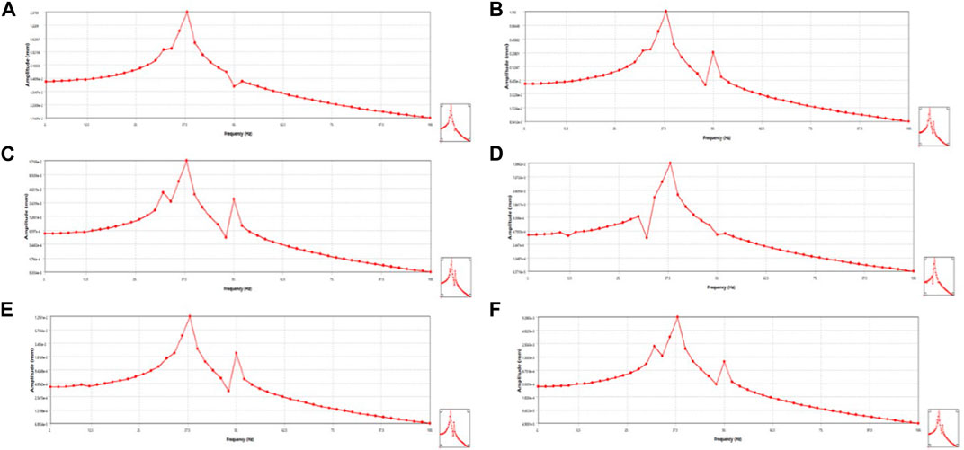
FIGURE 4. Calculated deformation curve of carbon fiber bow belt in (A) y-direction and (B) z-direction; deformation curve of incoming spindle in (C) y-direction and (D) z-direction; and deformation curve of outgoing spindle in (E) y-direction and (F) z-direction.
Figure 5 shows that the stress distribution on the incoming and outgoing spindles is maximum at the incoming disc bearing installation at 30.123 MPa, with a minimum at the end of the shaft of 200 Pa. At the bearing connection in the bearing box, the shaft also has a large stress concentration, with a value of 10.041 MPa or more; thus, it is necessary to strengthen the bearing assembly to prevent the machine from resonating.
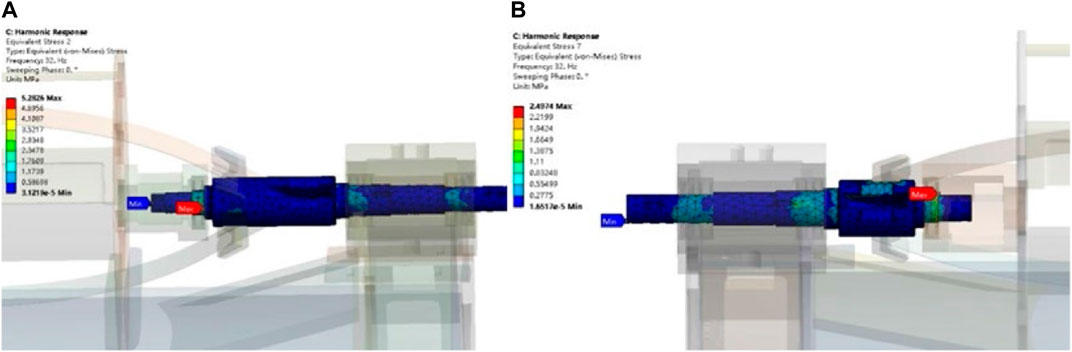
FIGURE 5. Stress nephogram of (A) incoming and (B) outgoing spindle with excitation force at 32 Hz.
3.3 Vibration damping solutions
From the overall results of the vibration analysis to determine the maximum resonance point and identify the root cause of the axial vibration, we found that the resonance appears at the right end of the bearing seat position. The center of gravity of the bearing force deviates from the geometric center of the bearing seat. The projection point of the excitation force does not coincide with the collection center of the bearing seat so that the bearing seat connection stiffness is low and the bearing seat produces axial sway, although the base of the machine has minimal impact. The rotating assembly was separated, some simplification operations were carried out, and the simplified model is shown in Figure 6A.
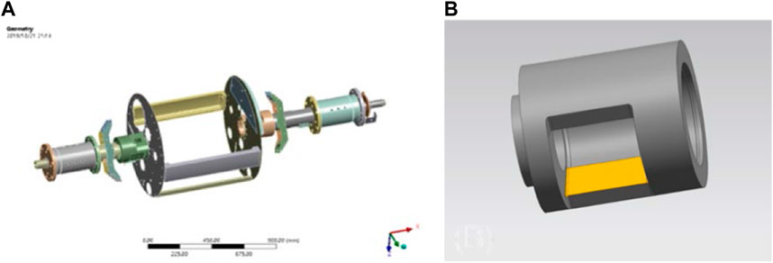
FIGURE 6. (A) Simplified spindle model and diagram of bearing thickening position and (B) the thickening position.
From consideration of the structural vibration results, the resonant frequency could be avoided and vibration reduced by changing the wall thickness of the right end bearing seat. As the model has many holes on both sides of the disc, and the shortest distance of the holes from the bearing seat is 4 mm, the inner wall must also be thickened to avoid stress concentration in the holes on the incoming disc after thickening the outer wall. The clearance between the inner wall of the bearing seat and the rotor is 6.25 mm, but because of bearing wear, the wall thickness of the bearing seat cannot increase beyond the maximum range of 4 mm. The thickening position is shown in Figure 6B (yellow area of symmetric thickening). There is also a gap between the bearing seat and the rotor assembly, and over time, the bearing seat will wear and the gap will increase; thus, it is difficult to avoid the resonant frequency. Wear can be reduced to some extent by using a sleeve and improving the lubrication system. After considering all the aforementioned factors, the wall thickness of the bearing seat was tested by increasing it 1 mm and 3 mm, and reducing it by 1 mm, and analyzing the modalities of the spindle. The results of the analysis using the ANSYS Workbench are shown in Table 3.
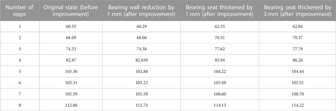
TABLE 3. First eighth order modal analysis of spindle (Hz).
From the results of modal analysis of the bearing seat improvement, it can be seen that reducing the bearing wall thickness by 1 mm did not have much effect on the modal values of the spindle and did not achieve avoidance of the resonant frequency. However, an appropriate increase in the wall thickness of the bearing seat did effectively avoid the resonant frequency, thus achieving vibration and noise reduction. Considering the structural machining and the friction between bearing and shaft, the maximum wall thickness of the bearing seat should be increased by 3 mm. By doing that, the original resonant frequency can be avoided at all vibration orders, which provides a good reference point for optimization of the structure.
4 Conclusion
In this study, a modal analysis of a structural model of a stranding machine was carried out, and the first eight orders of inherent frequencies and vibration patterns were obtained. The analysis of the inherent frequencies and vibration patterns of each order showed that when the machine was in normal operation, the operating frequency was located between the fourth- and fifth-order inherent frequencies, and the motor frequency was located between the sixth and seventh orders; thus, the machine was likely to resonate under normal operation at the given excitation frequency. The modal analysis of the key elements of the rotating part shows that the first-order inherent frequency of the bow belt was close to the motor frequency (50 Hz) under normal operating conditions and is the part that causes the resonance. It was found that the response patterns of the incoming spindle, outgoing spindle, and carbon fiber bow belt were basically the same, and resonance would occur at 32 Hz, 38 Hz, and 50 Hz in each. By analyzing the stress nephogram of the structure under the effect of a 32 Hz excitation frequency, we found that the stress values of the incoming spindle and outgoing spindle were larger at the bearing installation and smaller at the shaft end. The stress value of the bow belt was greatest at the bolt fixation and least at both ends, which indicates the parts to be optimized. Through modal analysis, we found that increasing the wall thickness of the bearing seat could effectively avoid the resonant frequency and achieve vibration reduction, providing the basis for design improvements and structural optimization in the future.
Data availability statement
The raw data supporting the conclusions of this article will be made available by the authors, without undue reservation.
Author contributions
Conceptualization, BL; methodology, KR; software, WT; validation, KR; investigation, QS; writing—original draft preparation, BL, KR, and CZ; writing—review and editing, KR; funding acquisition, KR. All authors have read and agreed to the submitted version of the manuscript.
Funding
The authors would like to thank the support of the Natural Science Foundation of Jiangsu (No. BK20220407).
Conflict of interest
The authors declare that the research was conducted in the absence of any commercial or financial relationships that could be construed as a potential conflict of interest.
Publisher’s note
All claims expressed in this article are solely those of the authors and do not necessarily represent those of their affiliated organizations, or those of the publisher, the editors, and the reviewers. Any product that may be evaluated in this article, or claim that may be made by its manufacturer, is not guaranteed or endorsed by the publisher.
Supplementary material
The Supplementary Material for this article can be found online at: https://www.frontiersin.org/articles/10.3389/fphy.2023.1159064/full#supplementary-material
References
1. Lv Y, Sui Z, Li LJ. Online monitoring system of cable based on microchip 51. 2020 IEEE Conference on telecommunications, Optics and computer science (TOCS) (2020). p. 72–5.
2. Cui XZ, Yuan LL, Chen X, Chen B. Research on development of smart grid in regional electricity market. AER-Advances Eng Res (2015) 12:1419–22.
3. Yong JY, Ramachandaramurthy VK, Tan KM, Mithulananthan N A review on the state-of-the-art technologies of electric vehicle, its impacts and prospects. Renew Sustain Energ Rev. 2015, 49, 365–85. doi:10.1016/j.rser.2015.04.130
4. Li H, Liu L, Luo WB, Zhang XB, Luo MY. Research on optimization method of wire and cable extrusion control system. Chin Automation Congress (2019) 1703–8.
5. Chen YD, Tai YP, Xu J, Xu XM, Chen N. Vibration analysis of a 1-DOF system coupled with a nonlinear energy sink with a fractional order inerter. Sensors. 2022, 22, 6408. doi:10.3390/s22176408
6. Qin XD, Lu C, Wang Q, Li H, Gui LJ. Modal analysis of helical milling unit. Adv Mater Res (2012) 482-484:2454–9. doi:10.4028/www.scientific.net/amr.482-484.2454
7. Zhong YH, Sun GH. Experimental investigation of the vibration and noise and structural optimization of motor. AER-Advances Eng Res (2015) 27:2201–6.
8. Wu S, Su T, Wang Z. Research on optimization design of cantilever beam for cantilever crane based on improved GA. Inf Technol J (2013) 12(14):2883–7. doi:10.3923/itj.2013.2883.2887
9. Zhang JJ, Zhong JT, He LL, Gao RZ. Modal analysis of the cable-stayed space truss combining ANSYS and MSC.ADAMS. Adv Mater Res (2010) 121-122:832–7. doi:10.4028/www.scientific.net/amr.121-122.832
10. Nygards T, Berbyuk V. Multibody modeling and vibration dynamics analysis of washing machines. Multibody Syst Dyn (2012) 27(2):197–238. doi:10.1007/s11044-011-9292-5
11. Zhang ZP, Liu HW, He WT, Gao YH. Vibration modal analysis and structural optimal design of car rear-view mirror based on ANSYS. Adv Mater Res. 2012, 549, 848–51. doi:10.4028/www.scientific.net/amr.549.848
12. Zheng ZC, Gao Y, Liu N, Zhang KJ, Chen HO, Huang XB, et al. The harmonic response analysis of engine block based on modal analysis. Appl Mech Mater (2012) 138-139:246–51. doi:10.4028/www.scientific.net/amm.138-139.246
13. Arbain A, Mazlan AZA, Zawawi MH, Radzi MRM. Modal and harmonic response analyses of the kenyir dam intake section. Lecture Notes Civil Eng (2020) 53:1055–63.
14. Kai R, WenCheng T, Jian W, Hui L, Fatigue reliability analysis and life bench test of buffer block in car damper, in: IEEE international conference on engineering, technology and innovation (ICE/ITMC), IEEE, 2018, pp. 1–6.
15. Wang K, Ren K, Zhang D, Cheng Y, Zhang G. Phonon properties of biphenylene monolayer by first-principles calculations. Appl Phys Lett (2022) 121:042203. doi:10.1063/5.0102085
16. Zhou J, Xu LY, Zhang AQ, Hang XC. Finite element explicit dynamics simulation of motion and shedding of jujube fruits under forced vibration. Comput Electron Agric (2022) 198:107009. doi:10.1016/j.compag.2022.107009
17. Zhou J, Xu LY, Zhao JW, Hang XC, Zhou HP. Effective excitation conditions for the intense motion of the ginkgo seed-stem system during mechanical vibration harvesting. Biosyst Eng (2022) 215:239–48. doi:10.1016/j.biosystemseng.2022.01.014
18. Wang YB, Zhao CC, Li XL. Vibration and noise analysis of flux-modulation double stator electrical-excitation synchronous machine. IEEE Trans Energ Convers (2021) 36(4):3395–404. doi:10.1109/tec.2021.3084607
19. Wang JW, Xu CS, Xu YA, Wang JF, Zhou WQ, Wang Q, et al. Resonance analysis and vibration reduction optimization of agricultural machinery frame-taking vegetable precision seeder as an example. Processes (2021) 9(11):1979. doi:10.3390/pr9111979
20. Bhore CV, Andhare AB, Padole PM, Chavan CR, Gawande VS, Prashanth VS, et al. Harmonic response analysis of photovoltaic module using finite element method. Machines, Mechanism and Robotics (2022) 1219–26.
21. Kurbet R, Doddaswamy V, Amruth CM, Kerur MH, Ghanaraja S. Frequency response analysis of spur gear pair using FEA. Mater Today- Proc 2022, 52, 2327–38. doi:10.1016/j.matpr.2021.12.517
Keywords: stranding machine, modal analysis, harmonic response analysis, vibration, structure
Citation: Ren K, Leng B, Zhang C, Sun Q and Tang W (2023) The dynamic investigation of intrinsic vibration characteristics of a stranding machine by the finite element method. Front. Phys. 11:1159064. doi: 10.3389/fphy.2023.1159064
Received: 05 February 2023; Accepted: 02 March 2023;
Published: 31 March 2023.
Edited by:
Guangzhao Wang, Yangtze Normal University, ChinaReviewed by:
Longfei Yang, Nanjing University of Science and Technology, ChinaYi Luo, Jiangsu Ocean University, China
Copyright © 2023 Ren, Leng, Zhang, Sun and Tang. This is an open-access article distributed under the terms of the Creative Commons Attribution License (CC BY). The use, distribution or reproduction in other forums is permitted, provided the original author(s) and the copyright owner(s) are credited and that the original publication in this journal is cited, in accordance with accepted academic practice. No use, distribution or reproduction is permitted which does not comply with these terms.
*Correspondence: Wencheng Tang, 101000185@seu.edu.cn