- 1Department of Naval Architecture, Ocean and Marine Engineering, University of Strathclyde, Glasgow, United Kingdom
- 2Department of Structural Engineering, University of California, San Diego, San Diego, CA, United States
To investigate the manoeuvring performance of a body-caudal fin robot fish, a numerical framework combining computational fluid dynamics and multi-body dynamics with a closed-loop control algorithm was established in this study. Within this framework, we modelled a body-caudal fin swimmer as a multi-body system with the shape of a NACA0012 hydrofoil. The manoeuvring performance was investigated by using different curvature magnitudes and distributions along the centre line (the curvature is defined by means of a curvature envelop function as part of the general body undulation equation). To characterize the turning performance, a new parameter named cost of manoeuvring (CoM) is proposed. This parameter provides a combined assessment of the turning radius, linear and angular velocity components, and power. It is found that when the body curvature is introduced, the swimmer switches from straight-line swimming to quasi-steady turning at a constant speed. Further investigations were conducted to study contributions of head and tail deformations on the turning performance by comparing predominantly head and tail curved envelopes. Results reveal that a tail-dominated envelope improves performance, whereas a head-dominated envelope has a negative effect.
1 Introduction
Through evolution, fish continuously adapt to their environment and develop local optimal combinations of physique and behaviour. Depending on their usage of paired fins or body undulation as the main thrust generating mechanism, fish are generally categorized as median-paired fin (MPF) and body-caudal fin (BCF) types [1]. However, some fish are observed to switch between MPF and BCF locomotor behaviours [2]. Species of fish that switch between these two locomotion behaviours, known as decoupled locomotors, usually live in complex environments in which agile acceleration, direction change and obstacle avoidance are necessary. On the contrary, coupled locomotors are observed to inhabit relatively simple environments [3]. These species (e.g., tuna) tend to specialise in steady rectilinear locomotion, such as cruising. In the past, most studies have focussed on steady fish locomotion [4, 5]. However, fish spend the majority of their time performing unsteady locomotion [6].
The term manoeuvrability is used to describe the ability to perform a range of unsteady motions, such as C- and S-starts, and turning manoeuvres [6]. For example, the agile manoeuvrability of a fish is displayed during C-starts when the fish accelerates from a stationary state by means of a single large sweep of its tail fin to create two distinct vortices that define the momentum and impulse at which the fish turns and accelerates [7]. Streamlined BCF fish moving at an initial velocity can perform unpowered turns due to their high fitness, characterized by the body length to thickness ratio, while unstreamlined MPF fish have to continuously generate thrust during turning manoeuvres due to their low fitness [8]. Unpowered turns may lead to smaller turning radii [9], while large animals with large inertia may prefer unpowered turns [3]. A simple relationship between turning radius R and body mass m,
Fish gain their high manoeuvrability from their inherently unstable motion. The quasi-steady state of straight swimming of a BCF swimmer relies on force symmetry over a full actuation cycle. Small perturbations of fluid flow or body motion lead to the loss of force equilibrium and a change in the heading direction [10]. During turning manoeuvres, fish may also use fins as control surfaces to generate a turning moment [6] or to balance forces [11]. Comprehensive knowledge of the manoeuvrability of fish and other aquatic animals may become useful to improve engineering designs.
Compared with a conventional rigid torpedo or open-frame ROVs and AUVs, bio-inspired underwater robots and vehicle platforms may feature significantly enhanced efficiency and manoeuvring capacity. Indeed, tests of a free swimming robot tuna demonstrated turning rates of up to 75° per second [12], exceeding the turning rates of 25–35° per seconds of a modern enhanced rigid hull AUV [13]. Further work on robotic fish manoeuvring can be found in the literature, for example, on C-starts [14] and path following patterns [15]. Robotic fish may perform turns with variable deflection angles across multiple links [16]. This raises the question of what kinematic parameters are energetically optimal.
An analysis of the fluid–structure interaction problem may provide further insights and opportunities to optimise the performance of bio-inspired robots. Computational fluid dynamics (CFD) is a powerful tool to compute time-dependent hydrodynamic forces and study the performance of aquatic systems. The latest CFD tools coupled with control algorithms enable dynamic simulations of unsteady phenomena and investigations into optimal control.
Simulations coupling CFD and control algorithms have been conducted, for example, on the optimal undulatory swimming of a single and a pair of fish [5], on the fluid–structure interaction between a self-propelled flexible plate near a rigid body [17] and on the energy extraction of an independently controlled caudal fin [18].
In this work, a multi-body CFD tool [19, 20] was extended by a linear feedback control algorithm to investigate the manoeuvrability of a BCF swimmer. Related CFD work on manoeuvring and control parameter tuning, turning performance and path following have been reported [21, 22]. In these studies, only a single distribution of the body curvature was considered. Therefore, simulations were conducted to address a knowledge gap on the manoeuvring performance of undulatory swimmers, specifically analyses of the turning performances for different body curvature distributions.
BCF swimmers achieve an agile turning performance by controlling the curvature of their bodies’ central line. To enable a bio-inspired robot to duplicate this feature, optimal control inputs are crucial. The present work aims to identify control parameters that enable BCF swimmers to achieve smaller turning radii at lower power consumption. To quantitatively characterize the tuning performance, we proposed a novel parameter, i.e., the CoM. As part of the discussion, the general mechanisms relating to BCF manoeuvring by means of the body curvature are presented as well as the performance of different curvature distributions; more specifically, constant curvature and linear curvature envelopes are analysed.
The paper is structured as follows: 1. Introduction, 2. Problem description, 3. Problem modeling, 4. Setup, 5. Results and discussions 6. Conclusion. In Section 3, the coupling of the simulation and its components are briefly described, including the multi-body algorithm, fluid solver and linear control algorithm. In Section 5, simulation results are provided in two parts. First, results for a constant curvature envelope at different magnitudes of the curvature are presented. Second, an investigation into the contribution of the head and tail curvature via a comparison between two linear curvature envelopes and a constant envelope is discussed.
2 Problem description
A BCF swimmer accelerates against surrounding fluid in a periodic motion by means of lateral undulation. Straight swimming or cruising is achieved through lateral force symmetry over one undulation cycle. By curving the body asymmetrically, the force imbalance results in a moment on the swimmer. BCF swimmers move their anterior body (head) and posterior body (peduncle and caudal fin) independently during turning manoeuvres [11]. The turning moment may be a combination of a posterior reactive force on the tail fin, anterior lift force, and reduced drag force by aligning towards the new swimming direction.
The curving of the central body line is a key mechanism of moment change in BCF manoeuvring [23]. To understand BCF swimmer manoeuvring, the turning performance of BCF locomotion with different curvature envelopes was investigated. Herein, a curvature envelope describes the curvature distribution along the central line. To investigate the self-propelled turning performance at different Reynolds numbers and curvature envelopes, the scenario in Figure 1 was selected. Two linear feedback controllers were used to reach the required speed and maintain straight-line swimming until the prescribed curvature is applied. From a state of rest, the swimmer will accelerate by means of undulation motion to a predetermined swimming speed to achieve a desired Reynolds number. When this forward velocity is reached, the body curves according to a prescribed curvature envelope. The investigation does not consider any behavioural factors and assumes that all body motions are focused on benefiting turning performance.
3 Problem modelling
In this work, a coupled CFD multi-body simulation environment was applied [19, 20]. The commercial CFD software package Ansys Fluent 22.1 was coupled with a multi-body dynamics algorithm utilising an in-house developed user-defined function (UDF). This method solves the internal and external dynamics of a multi-body system in a CFD environment at each time step through three recursions and one numerical integration. A linear feedback control algorithm completes the simulation setup. A control signal flow graph is shown in Figure 2. A detailed description of the CFD tool and validation results are given in Supplementary Appendix SA, SB and in the literature [19, 20].
3.1 Computation of hydrodynamic forces—computational fluid dynamics
The fluid domain, governed by the Naiver–Stokes equations, was solved using the finite volume method. The incompressible flow governing equations for continuity and momentum are given in Eqs. 1, 2, with
The transient equations are computed by a pressure–velocity coupling using a non-iteration time-advancement (NITA) scheme, which allows direct solutions with only one outer iteration and sub-iterations to support convergence. The momentum and continuity equations are decoupled in the selected NITA pressure-based solver fractional-step method (FSM). A relaxation factor was applied. For the transient terms, a first-order implicit time marching scheme was selected. Spatial discretisation and discretisation of the diffusive term were achieved by applying the least squares cell-based approach for the gradient and second-order upwind scheme. To improve accuracy, second-order pressure interpolation was selected.
The unstructured CFD mesh dynamically adjusts to the global motion of each surface node defined by the body motion of the swimmer. For a continuous flexible body, the lateral position of the surface points were linearly interpolated between the local coordinate system of the current and ascending body. To maintain a high mesh quality throughout the computational domain, the dynamic meshing function available in Ansys Fluent was selected. For small displacements, the mesh was adjusted by diffusion-based smoothing. For large displacements, remeshing of the unstructured mesh was applied. The unsteady time step and mesh sizing were selected based on the Courant convergence criteria.
3.2 Multi-body algorithm and swimmer kinematics
The multi-body algorithm describes the internal and external dynamics of a multi-body system by solving the generalised equation of motion in the Newton–Euler form shown in Eq. 3 via three recursive loops through the elements of the multi-body system. The components of Eq. 3 are the generalised force vector
A simplified fish geometry was considered a multi-body system in the shape of a 2D NACA0012 foil comprising body segments connected via actuated links along the central line that resemble muscle actuation. The NACA0012 geometry was separated into 10 equal cord length body segments with nine joints.
The local coordinate system
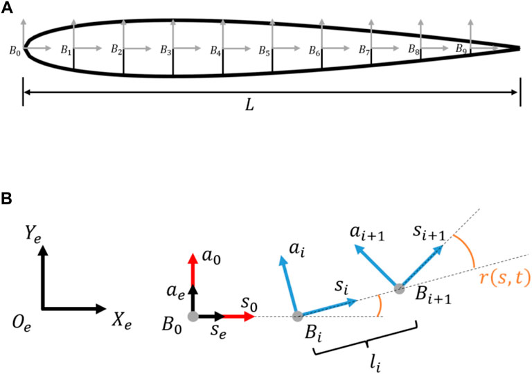
FIGURE 3. (A) Simplified fish geometry modelled as NACA0012. (B) Relation between global, local and reference coordinate systems, and the relative rotation between joints according to Eq. 4.
The rotational motion of a segment around its front linkage at location s is given by
where f is the undulation frequency and t is the time. The amplitude envelope
with
Second, a linear curvature envelope from the leading to trailing edge is described by
where coefficients
The total curvature of the swimmer is defined as the sum of the time-independent joint displacement over the swimmer length, which is as follows
Tables 1, 2 summarise the total curvature and coefficient values used in an investigation into the curvature magnitude in Section 5.1 and comparison of envelopes in Section 5.2 respectively. The coefficients

TABLE 2. Summary of coefficients used in constant and linear curvature envelopes with the total curvature remaining unchanged.
3.3 PID control
To investigate the turning performance at different forward velocities while maintaining a horizontal heading of the swimmer before turning, two linear feedback controllers were employed. Linear and angular swimming velocities are determined by the swimmer’s undulation amplitude and curvature. Therefore, to implement speed and heading control, control variables
Abrupt changes to
where
Equation 10 does not require a global reference to produce a travelling wave function; hence, it can be considered an open loop with control inputs
with
There are three individual time steps. First, the numerical simulation time step denoted as
3.4 Setpoint tracking for speed and navigation control
Two separate controllers for speed and steering control were used. The first PID controller controlled the speed by varying the undulation amplitude. The control coefficient
The control action is limited to
To achieve tracking of a set velocity
In this study, Vset is selected to achieve the desired Reynolds numbers Re = 2,000, 1,500 and 1,000; thus, Vset = 0.02, 0.015 and 0.01 m/s respectively.
The second PID controller adjusted the curvature magnitude by calculating the control coefficient
and the heading of the fish
To achieve LOS waypoint tracking the control error is defined as follows
The control action was limited to
3.5 Controller tuning and stability
Both speed and steering controllers were tuned to achieve a critically damped response, i.e., control gains
4 Setup
4.1 CFD simulation setup
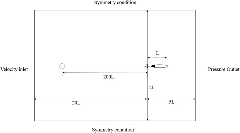
As shown in Figure 4, the computational domain is 25 L by 8 L, in which the swimmer’s leading edge is originally located at 5 L by 4 L from the bottom right corner. Herein, L is the fish body length. The unstructured CFD mesh sizing is
4.2 Kinematic parameters and cost of travel considerations
The Froude efficiency describes the useful output power over the input energy and is often used to assess engineering systems. With respect to the simplified BCF fish swimming scenario, it describes the relation between energy required to realise the body undulation and the swimming work. Herein, the swimming work is defined as the product of a longitudinal force on the body and swimming velocity. For a fish following a straight trajectory at constant speed, i.e., moving at a quasi-steady state, the cycle-averaged longitudinal force is zero due to the balance between the thrust and drag. The resulting Froude efficiency is zero and therefore not applicable. First mentioned as Self-Propelled Fitness [26] and later proposed as an efficiency measure [27], the quasi-propulsive efficiency is defined as
The linear manoeuvrability number (LMN), first mentioned to assess the manoeuvrability of an on-land hexapod [29], has also been used to quantify fish manoeuvrability [6]. The LMN is defined as the ratio of the time integral of the force impulse perpendicular to the forward momentum.
Ideally, a quantitative measure of manoeuvrability must provide a combined assessment of power consumption as well as linear and angular displacement. In that sense, CoT and LMN are not suitable. In this study, a modified cost of travel function for turning is applied. The cost of manoeuvring (CoM) is defined as the ratio of the cycle averaged input power to global angular velocity
The average input power was calculated as the sum of all joints’ cycle-averaged power (defined as the product of cycle-averaged torque and angular velocity), which is given as follows
The global angular velocity was calculated using the radius
Analogous to CoT, CoM relates the energy spent per unit distance travelled; therefore, a performance increase is indicated by a smaller CoM. With its current definition, CoM is not suitable to assess straight swimming.
5 Results and discussions
5.1 Effect of added body curvature and quasi-steady turning state
Undulatory swimming shows a characteristic periodicity stemming from vortex shedding during the peak and trough of the body motion. Straight-line swimming at a constant cycle-averaged speed is described as the quasi-steady state at which body forces are in balance over one undulation cycle. To initiate turning, force symmetry is broken by the curving of the body’s central line. Changes in the position of the centre of mass, moment of inertia, and resulting biased cycle-averaged loads lead to a net moment and subsequent angular acceleration. Figure 5 plots the yaw moment of an accelerating and turning swimmer, according to the setup of Figure 1 for Re = 2,000 and constant curvature. Three distinct periods are visible, i.e., a transition period from a static state to a quasi-steady state (t = 0–25 s), a transition period during which the central line curves into an equally distributed curvature of κ = 8.1 rad/m (t = 25–27 s) and, finally, a period of a quasi-steady turning state (t = 27–35 s).
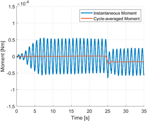
FIGURE 5. Instantaneous moment and cycle-averaged moment showing the three transition states. Re = 2000.
The vorticity contour of each period is shown in Figure 6. Beginning at the quasi-steady state, the reverse Karman vortex street remains horizontal and periodically symmetric. During the transition stage, the body curves and changes the heading direction. Meanwhile, vortices are shed at a non-zero angle. In the third stage, the re-oriented swimmer continues undulation around the curved central line and reaches the quasi-steady turning state. It is found that the time-averaged angular velocity appears to be zero during straight swimming (
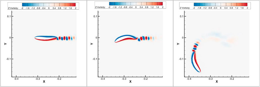
FIGURE 6. Vorticity contour of the constant envelope: left-quasi-steady state at t = 25 s, middle-transition state at t = 26.4 s, and right-quasi-steady turning state at t = 34.4 s. Re = 2,000.
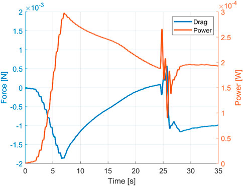
The input power to fulfil the undulation motion reflects the effort of the swimmer to accelerate against the surrounding fluid. As shown in Figure 7, during the initial acceleration, the longitudinal force peak coincides with an input power peak at approximately t = 7 s. Herein, the longitudinal force and power peak also correspond to the acceleration peak. From there onwards, the swimmer continues to accelerate to the targeted velocity but at a decreasing rate. At the quasi-steady turning state from approximately t = 27 s, the cycle-averaged power converges to a stable value close to zero. The power consumptions during the quasi-steady state straight-line swimming and turning are close to each other, which suggest that the extra effort required for turning, once it is initiated, is insignificant.
Observations of the aforementioned three states are consistent across different curvature magnitudes and investigated Reynolds numbers (Re = 1,000, 1,500 and 2,000). A linear increase in the magnitude of the constant curvature envelope results in a close to linear increase in power consumption. The resulting turning angle decreases with increased curvature yet flattens out at the end, as shown in Figure 8. This results in a decreasing CoM for an increased curvature. For all Reynolds numbers, a similar pattern was observed, where the radius is the dominant variable in the CoM calculation due to its reduction with an increased curvature.
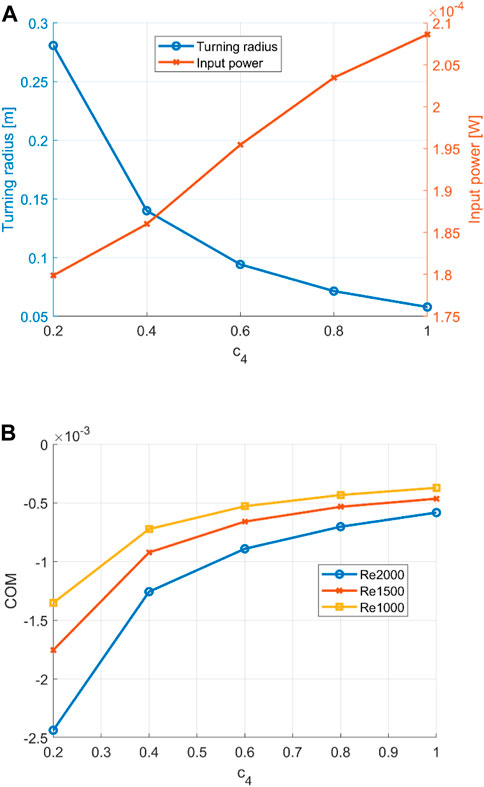
FIGURE 8. (A) Turning radius and power input for an increasing curvature at Re = 2000. (B) cost of manoeuvring for increasing curvature. Re = 1,000, 1,500, and 2,000.
5.2 Comparison of curvature envelopes
Fish turn both their head and bend their tail in a turning manoeuvre [11]. In the following, the contribution of the head and tail movement towards turning was investigated by comparing three curvature envelopes with the same total curvature. The three selected envelopes are a constant envelope (equal offset across all joints), a linearly increasing envelope denoted as
As shown in Figure 8A, the cycle-averaged drag shows two distinguishable phases during the turning transition period. These are highlighted as phases I and II. Following general observations, negative drag forces correspond to swimming velocity acceleration and positive drag forces correspond to swimming velocity deceleration in the heading direction. Therefore, Phase I may be associated with the initial body curving against the longitudinal moving flow, leading to an increase in drag forces and subsequent deceleration. Likewise, Phase II may be associated with the first full sweep with a curved centre line, increasing the thrust and thus acceleration.
When comparing the constant envelope with the average of both linear envelopes, the curves show close agreement (see Figure 9). It leads to the conclusion that the constant envelope can be segregated into head and tail contributions. According to Figure 9B, the predominantly tail turning envelope achieves a sharper turn with a smaller turning radius. This, together with the close match between a constant envelope and averaged linear envelopes, suggests that head turning has a negative effect on the turning performance.
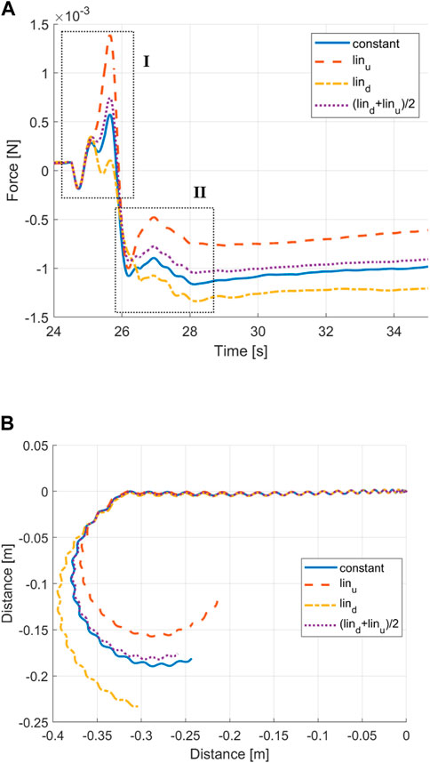
FIGURE 9. (A) Time histories of the drag force with different curvature envelopes. (B) Trajectory of a constant envelope, linear envelopes, and averaged linear envelopes.
A comparison of the heading angle and passing fluid velocity angle may provide an explanation. As shown in Figure 10, in the predominantly tail curving envelope, the heading angle leads the fluid angle (i.e., the relative angle of attack of the flow). In contrast, for the predominantly head curving envelope, after an initial peak, the heading angle is behind the fluid angle. For the constant envelope, the angles are closely aligned, with the heading angle slightly leading the velocity angle.
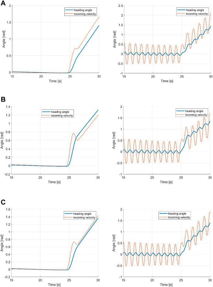
FIGURE 10. Instantaneous and cycle-averaged heading and incoming flow velocity angles for (A) tail turning, (B) head turning, and (C) constant envelope.
A leading heading angle may positively influence the turning performance, where it provides additional moment for the rotation and reduces the counter rotation moment. Figure 11 shows a schematic representation to highlight the mechanism. A strong tail sweep may provide sufficient moment and energy to turn the swimmer in front of the passing fluid stream by providing additional pressure force to create a moment in the turning direction. Meanwhile, as the tail now sweeps in the opposite direction, the fluid force acting on the head may provide a dampening effect that reduces the counter turning moment. Evidence of this can be seen in the reduced counter turning moment amplitude shown in Figure 12. On the other hand, a curved head may negatively influence the turning performance where it does not create sufficient moment to rotate the swimmer in front of the fluid stream. Additionally, the reactive force during curving of the head leads to a counter turning moment and, as a result, reduces the positive turning effect of the tail curvature. Furthermore, a curved head may provide less resistance during counter turning undulation.

FIGURE 11. Schematic representation showing the heading angle effect on moment during undulation amplitudes.
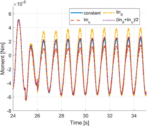
FIGURE 12. Time histories of the cycle-averaged moments with a constant envelope, linear envelopes, and averaged linear envelopes.
The negative contribution of head turning on the turning performance is also visible in the cycle-averaged power curve in Figure 13.
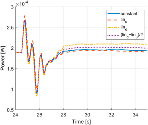
FIGURE 13. Time histories of the cycle-averaged power of a constant envelope, linear envelopes, and averaged linear envelopes.
6 Conclusion
This work focussed on the unsteady swimming performance of a BCF swimmer during turning. A controllable self-propelled simulation of a BCF swimmer that performs a turning manoeuvre at an intended forward velocity and different body curvature envelopes was created by adding a linear feedback control algorithm to a CFD multi-body tool. By modelling the simplified fish geometry as a multi-body system, information is obtained of joint torque resembling a bio-inspired robotic system so that it is possible to find measures to improve the controllability and turning performance. Implementing a control function within a high-fidelity fluid solver allows for accurate force representation and detailed fluid flow analyses.
Results show the swimmer reaching a quasi-steady turning state similar to the quasi-steady state during rectilinear swimming. The swimmer switches from a rectilinear trajectory to a curved trajectory of a stable, periodically repeating state of turning through a transition stage, during which the body curvature is added. For a constant envelope, it is shown that the turning radius is related to the magnitude of the body curvature. With increased curvature, the power consumption increases linearly, while the turning radius decreases but eventually flattens out.
To identify the contributions of head and tail curvatures on the turning performance, we have compared predominantly head curved, predominantly tail curved and constantly distributed curvature envelopes. The investigation revealed symmetry between the head-dominated and tail-dominated envelopes so that the averaged results show a close agreement with the constant envelope in terms of force and trajectory. This leads to the conclusion of distinguishable contributions of the head and tail curvature on the performance. Furthermore, simulation results show the overall superior turning performance of the predominantly tail curved envelope, highlighting the negative effect of head turning. This leads to finding control parameters that enable smaller turning radii at lower power consumption. Unlike most of the existing research, the present study considers a more biologically realistic scenario by considering a variable body curvature. Therefore, the findings may be useful for the design of bio-inspired underwater robots with regards to manoeuvrability and stability.
This work proposes a new quantitative measure of turning performance, the cost of manoeuvring. CoM provides a combined assessment of power, turning radius and speed. Simulations show that the CoM is improved in a larger body curvature, with a reduced radius as the dominant factor. When the power linearly increases, the radius linearly decreases but flattens out. Among the three curvature envelopes that were examined, the predominantly tail curving envelope achieves the smallest turning radius and best power performance and, subsequently, the best CoM.
Data availability statement
The raw data supporting the conclusion of this article will be made available by the authors, without undue reservation.
Author contributions
MW and QX contributed to the conception and design of the study. All authors contributed to the article and approved the submitted version.
Funding
MW received support from the PhD Stipend University of Strathclyde John Anders Research Award with the support from Verlume Ltd. and EPSRC SuperGen Flexfund EP/S000747/1. This work was made possible by Strathclyde University’s John Anderson Research Award and industry support by Verlume, formerly EC-OG, of Aberdeen Scotland, to the first author. Further financial support was provided by the EPSRC SuperGen Offshore Renewable Energy (ORE) Hub Flexible Fund Program Grant “Autonomous Biomimetic Robot-fish for Offshore Wind Farm Inspection” EPSRC (grant number EP/S000747/)
Acknowledgments
The authors would like to express special thanks to Edward Wright for proofreading the final manuscript.
Conflict of interest
The authors declare that the research was conducted in the absence of any commercial or financial relationships that could be construed as a potential conflict of interest.
Publisher’s note
All claims expressed in this article are solely those of the authors and do not necessarily represent those of their affiliated organizations, or those of the publisher, the editors, and the reviewers. Any product that may be evaluated in this article, or claim that may be made by its manufacturer, is not guaranteed or endorsed by the publisher.
Supplementary material
The Supplementary Material for this article can be found online at: https://www.frontiersin.org/articles/10.3389/fphy.2023.1220596/full#supplementary-material
References
1. Lindsey C. Form, function and locomotory habits in fish. In: Locomotion. New York, NY: Academic Press (1978).
2. Gerstner CL. Maneuverability of four species of coral-reef fish that differ in body and pectoral-fin morphology. Can J Zoolog (1999) 77:1102–10. doi:10.1139/z99-086
3. Blake R, Chan K. Models of the turning and fast-start swimming dynamics of aquatic vertebrates. J fish Biol (2006) 69:1824–36. doi:10.1111/j.1095-8649.2006.01251.x
4. Lighthill MJ. Large-amplitude elongated-body theory of fish locomotion. Proc R Soc Lond Ser B. Biol Sci (1971) 179:125–38. doi:10.1098/rspb.1971.0085
5. Maertens AP, Gao A, Triantafyllou MS. Optimal undulatory swimming for a single fish-like body and for a pair of interacting swimmers. J Fluid Mech (2017) 813:301–45. doi:10.1017/jfm.2016.845
6. Drucker E, Lauder G. Wake dynamics and fluid forces of turning maneuvers in sunfish. J Exp Biol (2001) 204:431–42. doi:10.1242/jeb.204.3.431
7. Epps BP, Techet AH. Impulse generated during unsteady maneuvering of swimming fish. Experiments in Fluids (2007) 43:691–700. doi:10.1007/s00348-007-0401-4
8. Blake R. On ostraciiform locomotion. J Mar Biol Assoc United Kingdom (1977) 57:1047–55. doi:10.1017/s0025315400026114
9. Fish FE. Balancing requirements for stability and maneuverability in cetaceans. Integr Comp Biol (2002) 42:85–93. doi:10.1093/icb/42.1.85
10. Webb PW, Weihs D. Stability versus maneuvering: Challenges for stability during swimming by fishes. Integr Comp Biol (2015) 55:753–64. doi:10.1093/icb/icv053
11. Weihs D. A hydrodynamical analysis of fish turning manoeuvres. Proc R Soc Lond Ser B. Biol Sci (1972) 182:59–72. doi:10.1098/rspb.1972.0066
12. Anderson JM, Chhabra NK. Maneuvering and stability performance of a robotic tuna. Integr Comp Biol (2002) 42:118–26. doi:10.1093/icb/42.1.118
13. Randeni S, Sacarny M, Benjamin M, Triantafyllou M. Morpheus: An A-sized AUV with morphing fins and algorithms for agile maneuvering (2022). Available at: https://arxiv.org/abs/2212.11692 (Accessed December 22, 2022).
14. Liu J, Hu H. Mimicry of sharp turning behaviours in a robotic fish. In: Proceedings of the 2005 IEEE International Conference on Robotics and Automation; April 18-22, 2005; Barcelona, Spain. IEEE (2005). p. 3318–23.
15. Struebig K, Bayat B, Eckert P, Looijestijn A, Lueth TC, Ijspeert AJ. Design and development of the efficient anguilliform swimming robot—mar. Bioinspiration and Biomimetics (2020) 15:035001. doi:10.1088/1748-3190/ab6be0
16. Yu J, Liu L, Wang L, Tan M, Xu D. Turning control of a multilink biomimetic robotic fish. IEEE Trans Robotics (2008) 24:201–6. doi:10.1109/tro.2007.914850
17. Luo Y, Wright M, Xiao Q, Yue H, Pan G. Fluid–structure interaction analysis on motion control of a self-propelled flexible plate near a rigid body utilizing PD control. Bioinspiration and Biomimetics (2021) 16:066002. doi:10.1088/1748-3190/ac1cee
18. Gao A, Triantafyllou MS. Independent caudal fin actuation enables high energy extraction and control in two-dimensional fish-like group swimming. J Fluid Mech (2018) 850:304–35. doi:10.1017/jfm.2018.456
19. Hu J. Numerical study on hydrodynamic performance of bio-mimetic locomotion (2016). Available at: http://purl.org/coar/resource_type/c_db06 (Accessed May 9, 2023).
20. Li R, Xiao Q, Liu Y, Hu J, Li L, Li G, et al. A multi-body dynamics based numerical modelling tool for solving aquatic biomimetic problems. Bioinspiration and biomimetics (2018) 13:056001. doi:10.1088/1748-3190/aacd60
21. Tian R, Li L, Wang W, Chang X, Ravi S, Xie G. CFD based parameter tuning for motion control of robotic fish. Bioinspiration and Biomimetics (2020) 15:026008. doi:10.1088/1748-3190/ab6b6c
22. Hess A, Tan X, Gao T. CFD-based multi-objective controller optimization for soft robotic fish with muscle-like actuation. Bioinspiration and biomimetics (2020) 15:035004. doi:10.1088/1748-3190/ab6dbb
23. Gray J. Directional control of fish movement. Proc R Soc Lond Ser B, Containing Pap a Biol Character (1933) 113:115–25. doi:10.1098/rspb.1933.0035
24. Ijspeert AJ. Central pattern generators for locomotion control in animals and robots: A review. Neural networks (2008) 21:642–53. doi:10.1016/j.neunet.2008.03.014
25. Kern S, Koumoutsakos P. Simulations of optimized anguilliform swimming. J Exp Biol (2006) 209:4841–57. doi:10.1242/jeb.02526
26. Barrett DS. Propulsive efficiency of a flexible hull underwater vehicle. Cambridge, MA: Massachusetts Institute of Technology (1996).
27. Maertens A, Triantafyllou MS, Yue DK. Efficiency of fish propulsion. Bioinspiration and biomimetics (2015) 10:046013. doi:10.1088/1748-3190/10/4/046013
28. Walker JA. Does a rigid body limit maneuverability? J Exp Biol (2000) 203:3391–6. doi:10.1242/jeb.203.22.3391
29. Jindrich DL, Full RJ. Many-legged maneuverability: Dynamics of turning in hexapods. J Exp Biol (1999) 202:1603–23. doi:10.1242/jeb.202.12.1603
30. Mjaavatten A. Curvature of a 1D curve in a 2D or 3D space (2021). Available at: https://www.mathworks.com/matlabcentral/fileexchange/69452-curvature-of-a-1d-curve-in-a-2d-or-3d-space (Accessed July 10, 2023).
Keywords: bio-inspired, autonomous underwater vehicle, computational fluid dynamics, feedback control, body-caudal fin, manoeuvring
Citation: Wright M, Xiao Q and Zhu Q (2023) Combined hydrodynamic and control analysis on optimal kinematic parameters for bio-inspired autonomous underwater vehicle manoeuvring. Front. Phys. 11:1220596. doi: 10.3389/fphy.2023.1220596
Received: 10 May 2023; Accepted: 03 July 2023;
Published: 28 July 2023.
Edited by:
Fang-Bao Tian, University of New South Wales Canberra, AustraliaReviewed by:
Cetin Canpolat, Çukurova University, TürkiyeMofeed Turky Rashid, University of Basrah, Iraq
Copyright © 2023 Wright, Xiao and Zhu. This is an open-access article distributed under the terms of the Creative Commons Attribution License (CC BY). The use, distribution or reproduction in other forums is permitted, provided the original author(s) and the copyright owner(s) are credited and that the original publication in this journal is cited, in accordance with accepted academic practice. No use, distribution or reproduction is permitted which does not comply with these terms.
*Correspondence: Qing Xiao, cWluZy54aWFvQHN0cmF0aC5hYy51aw==
 Marvin Wright
 Qing Xiao1*


