Bulk superconducting materials as a tool for control, confinement, and accumulation of polarized substances: the case of MgB2
 G. Ciullo1,2*
  L. Barion1,2 M. Contalbrigo2 L. Del Bianco1,2 P. Lenisa1,2
  F. Spizzo1,2 M. Statera3 G. Tagliente4
- 1Dipartimento di Fisica e Scienze della Terra, University of Ferrara, Ferrara, Italy
- 2Istituto Nazionale di Fisica Nucleare (INFN)–Ferrara Division, Ferrara, Italy
- 3Laboratori Acceleratori e Superconduttività Applicata (LASA), Istituto Nazionale di Fisica Nucleare–Milano Division, Milano, Italy
- 4Istituto Nazionale di Fisica Nucleare (INFN)–Bari Division, Bari, Italy
Providing strong magnetic holding fields while at the same time guaranteeing shielding from unwanted external fields is a key requirement for the accumulation, preservation, and transport of nuclear-polarized materials: it is a crucial achievement for its exploitation in fusion test facilities and particle physics. High-temperature bulk superconducting materials represent an innovative and promising solution, as they are easily machinable and can be cooled by a coldhead. This work considers a bulk MgB2 superconducting hollow cylinder, and the successful preliminary studies, performed by measuring trapped fields in the order of 1 T in its center, encouraged us to upgrade the prototype apparatus for deep insight and knowledge. The new system allows working at a lower temperature of 8 K, exchanging cylinders and returning to working conditions in 1 day, and mapping the transverse fields along the radial coordinate (in 11 mm) and along the symmetry axis (in 48 mm). Then, it allows us to find the proper geometry and the production procedure for its use in a fusion test facility. The commissioning of the upgraded system provides results already useful for polarized fusion fuel, for instance, as a holding field for recombined hyper-polarized molecules from the recombination of atomic polarized beams, and it also gives the possibility of investigating the use of MgB2 in polarized nuclear targets.
1 Introduction
The strong demand for clean energy encourages scientists to contribute to these social efforts [1]. Since the 1980s, there have been suggestions of possible advantages coming from the use of nuclear-polarized reactants for fusion [2–4].
The well-known results on spin 1/2 (3He) – spin 1 (D) fusion reactions, shown on cross sections and differential-cross sections on collision experiments [5], open a variety of proposals and dreams on the field of nuclear fusion, but some questions require answers:
• Can we have fuel with sufficient density and polarization satisfying fusion requirements?
• Can the polarization survive in fusion environments?
• How can we manipulate the fuel for fusion facilities and their environments?
Magnetic fields are required to maintain the polarization of polarized nuclear substances in various activities and during transportation. Specifically, the main purpose of this contribution is to provide holding fields for polarized fuel in fusion tests [6]. Ideas and support on this topic come from studies and developments on spin-dependent studies in nuclear and subnuclear physics [7] in which nuclear-polarized targets are used.
A hollow bulk superconductor can hold polarization substances inside itself, provide the required holding fields, and shield external fields [8,9]. These features are important improvements with respect to conventional coil-based solutions [10] and can be hosted in the production system of nuclear-polarized targets. Finally, they become useful for the preparation of nuclear-polarized fuels.
Additional advantages include minimal space needed to fit in the experimental environments, maximum field compactness, absence of heat loads from current leads, and the capability to operate without stabilizers. Furthermore, because MgB2 has low mass density and is made of low atomic number elements, the reaction products experience less energy losses in the path of the material.
MgB2, as a superconductor material, has adequate critical current, critical field, critical temperature (39 K), and machinability [11]. Concerning the temperature, polarized hydrogen or deuterium targets require cryogenic temperatures well below the critical temperature of the MgB2, which, therefore, can be easily matched or incorporated within their cooling systems. Finally, the whole system can be easily moved from the preparation site and transported to the experimental and test facilities.
Our starting point has been the interest in this material as a magnetic field generator for high-energy physics nuclear targets [7]. In recent years, the nuclear spin physics community has shown increasing interest in exploiting the experience and knowledge acquired in the fields of nuclear and subnuclear fundamental physics to nuclear fusion programs [1].
Direct contact with one of the inventors [12] of a technique for the MgB2 synthesis gives us the chance to undertake feasibility studies to tailor the work to specific requirements.
In this article, we will start with our preliminary feasibility study and apparatus [13], which brought us to the present upgrading. This information is useful for deep understanding and monitoring of the behavior of bulk MgB2 hollow cylinders that can address the choice of the proper production procedure to be implemented in fusion programs with polarized fuel and polarized nuclear targets.
2 Materials and equipment
The material chosen for our investigation is MgB2, obtained by the reactive liquid infiltration (RLI) method. This technique, proposed and invented by an Italian group [12], allows the production of massive samples of different geometries [14]. It is promising with respect to other techniques: the hot isostatic pressing technique proposed by a Japanese group [15] and the Mg vapor sintering on B fibers technique proposed by an American group [16].
We have implemented our first prototype for feasibility studies using an MgB2 cylinder, machined from materials obtained starting with boron grains with a large size variability (from ∼1 μm to ∼200 μm), which has provided promising results [13]. We are encouraged to upgrade the preliminary system for more detailed investigations of different production procedures while also implementing the field mapping inside the cylinder. In the following, we will link the description of the previous installation, giving evidence on the upgrading and the possibility of new monitoring of the behavior of various samples under study.
After upgrading and commissioning the new system, we plan to test additional cylinders produced using boron grains of different sizes. In particular, we will focus on three MgB2 batches produced with a maximum boron grain size of 40 µm, 100 µm, and 160 μm, respectively [17].
The prototype apparatus described in a previous article [13] has been upgraded. Figure 1 shows the present configuration on which we will show the modifications applied for better operational use.
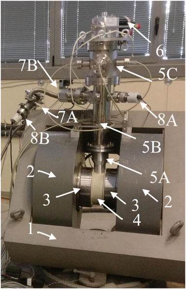
Figure 1. Picture of the overview of the present setup after its upgrading. Magnet: iron yoke (1), coils (2), and iron poles (3). In the nylon support (4), fixed to the poles, the bottom aluminum chamber (5A) of the vacuum system is inserted and connected to a stainless-steel chamber (5B); this chamber is fixed to the yoke thanks to two arms, on which a ring is welded. On the side of the chamber (5B), one turbo-molecular pump is attached (7B) in series with a second one (7A). On the opposite side, a dual Penning/Pirani vacuum gauge (8A) and a similar one (8B) is attached between the two turbopumps. On the chamber (5B), a new chamber (5C) has been installed, which hosts two DN40CF service flanges, facing each other, and at 90°, two DN63CF flanges, also facing each other. On the DN150CF top flange of the chamber (5C), the new coldhead (6) is connected with a custom 0–length flange.
For the feasibility studies, a hollow cylinder sample of MgB2, having a length of 86 mm and an outer diameter of 39 mm, was installed. It has a nominal thickness of 2 mm, tapering from 2 mm in the middle to 1 mm at the edges. We obtained very promising results concerning the trapped magnetic field (942 mT) and the shielded magnetic field (900 mT) with an applied external field of 980 mT at the temperature of 13 K. The trapped field lasts longer than 6 days. In the following, we will present the preliminary system, which is our starting point for the final upgraded system, and the methods used in the upgrade.
The prototype is shown in Figure 2. The subsequent modifications are shown in Figure 3. The items are evidenced in emphasized characters, which will be described for the prototype and subsequent modifications.
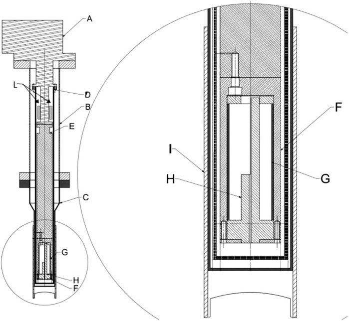
Figure 2. Drawing of the preliminary feasibility study apparatus, with details of the inner parts of the vacuum chambers and the cylinder holder: the Edwards 6/30 coldhead (A), exchanged with the new one (6) in Figure 1; stainless steel vacuum chamber (B) ≡(5B) in Figure 1; aluminum vacuum chamber (C) ≡(5A) in Figure 1; the copper-thermal shield (D), connected to the first stage of the coldhead; this one has been renewed, with (h) in Figure 3, following the same design and geometry; the copper rod (E), connected to the second stage of coldhead, has been redesigned and reduced in size in the upgraded system, (d1) in Figure 3, the diameter unless at the bottom part, (d2), equipped with eight cylindrical pits that host eight heater cartridges; a copper chamber (F) that hosts the cylinder, simply named the sample can, with a screwable cover on the bottom to allow the insertion of cylinders; MgB2 cylinder (G); PFTE old Hall probe holder (H); nylon support (I) ≡ (4) in Figure 1; the heaters’ collar (L), clamped on the second stage coldhead. In the upgraded system, the heaters are moved closer to the sample can: (d2) in Figure 3.
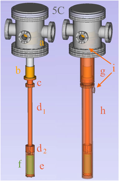
Figure 3. Drawing of the connections of the parts inside the chambers: the new chamber (5C), on which is connected the new coldhead within the orange stage surfaces: (a) the first and (b) the second. On the left side: a transition (c) adapts the new coldhead to the previous copper rod connection on the second stage (b); new copper rod: the diameter has been reduced (d1) from the connection at the second stage till the terminal part (d2) on which eight pits are drilled to host four heater cartridges; connected to this terminal part of the copper rod is the sample can (e), shown transparently to see inside the cylinder (f) On the right side: top (g) and bottom (h) parts of the copper thermal shield, connected to the first stage of the coldhead ports (i) as feed-throughs for the wires and cables of the sensors in the holder of sensors. In the top part, there is another similar port on the opposite side of the one visible below the transparent chamber (5C).
Cryogenic Unit: The superconducting cylinder was cooled by a coldhead (Edwards 6/30), driven by its helium compressor (Cryodrive 3.0), having a nominal temperature and a cooling power of 77 K and 30 W, respectively, on the first stage and 10 K and 6 W on the second stage. Our preliminary system has allowed us to reach a minimum temperature ∽ of 12.5 K.
For the upgrade, we have borrowed a new coldhead from our colleagues [18] (SHI-Sumitomo RDE–418D4), driven by its helium compressor (F–50H): this new cooling system allows us to work in more stable conditions and reach a still lower temperature (∽ 8 K). The nominal temperatures and cooling powers are, respectively, 50 K and 42 W on the first stage and 4.2 K and 1.8 W on the second stage. With this new coldhead, we have solved the stability problems that have limited our investigations in the feasibility studies.
In the prototype system, the sample temperature was controlled by a home-made resistive heater made by welding small cartridge heaters in cylindrical pits in a copper collar, cut into two halves that were clamped on the second stage of the coldhead (L in Figure 2), taking care to make good thermal contacts. A cryogenic linear temperature sensor (CLTS) was glued on half of the collar for temperature control and monitoring by an ITC-503S multipurpose controller (Oxford Instruments).
In the upgraded system, similar heater cartridges were inserted and welded in pits, symmetrically and peripherally drilled directly on the bottom part (d2 in Figure 3) of the copper rod (d1), as close as possible to the copper sample holder, named simply “sample can” (F) in Figure 2 for the prototype and (e) in Figure 3 for the upgraded system. In this way, we gained better control of the temperature of the cylinder and reduced the time required for its heating procedures.
The sample can hosts the cylinder, (G) in Figure 2 for the prototype and (f) in Figure 3 for the upgraded system. Inside the cylinder was a sensor holder (H) in (Figure 2) in the prototype. For the upgraded system, a new holder with more sensors has been designed and assembled. The new sensor holder will be described in detail in this report in connection with the results obtained for the commissioning of the present system.
External magnet: The magnetic field is provided by a VARIAN electromagnet (model V3603) with a nominal maximum current of 180 A. An available power supply (Agilent 6692A), remotely controlled via a GPIB interface, allows a 110 A feed, providing a magnetic field of 980 mT, measured in the middle of the poles by a Hall sensor (Arepoc HHP-NU).
In the upgrade, we use a new 200 A/50 V power supply (CAEN NGPS 200–50–Enhanced), controlled via an ethernet communication port. Powering the magnet at its maximum allowed current (180 A), we measured 1.2 T in the middle of the poles. The required magnetic field for fusion application is in the range of 1 T, which matches exactly with the system used to produce hyper-polarized molecules as fusion fuel from the recombination of a polarized atomic beam [6].
Vacuum system and thermal insulation: Figure 1 shows the present upgraded system.
We use the two existing cylindrical chambers from the preliminary vacuum system: the bottom one (5A) in Figure 1 is in aluminum because it is placed between the magnetic field poles (3), and the upper one is in stainless steel (5B), on which the Edwards 6/30 coldhead can be connected with a custom 0-length flange. The two chambers are connected by two DN100LF flanges.
For the upgraded system, a new stainless-steel chamber (5C in Figure 1) was required to fit the new coldhead. The design of the upgrade preserves the opportunity to return to the prototype configuration. The stainless-steel chamber (5C) is equipped on the top with a fixed DN150CF flange, on which the new coldhead is connected. A different custom 0-length flange is required for this new coldhead. On the bottom of the chamber (5C), a rotatable DN150CF flange is available for the connection to the similar one on the top of the chamber (5B). On the side, the chamber (5C) is equipped with two DN40CF flanges, facing each other, and with the other two DN63CF flanges at 90° with respect to the previous two, also facing each other. All these flanges are available for service feed-throughs, and three of them are used for the Sub-D-15 feed-throughs on the DN40CF 0-length flanges, which are also visible in Figure 1.
The stainless-steel chamber (5B) is equipped with a DN150CF flange on the top for its connection with the aforementioned chamber (5C) and on its side with a DN63CF flange for a turbo pump (Turbo-V 81-M from Agilent), backed by a scroll pump (Varian SH110) and with other two DN40CF flanges: one for a dual Penning/Pirani gauge (compact full range PKR 251 from Pfeiffer Balzers), and the other for service feed-throughs. We connected a DN40CF T-piece to have two feed-throughs available. In the upgraded configuration, the service feed-throughs were installed on the side flanges of the chamber (5C), which are visible in Figure 1. A Pirani gauge (Pfeiffer PTR81) is connected on the inlet of the scroll pump, backing the turbo pump.
In the upgraded system, we exchanged the aforementioned turbo pump with a 70 L s−1 (TV70LP Macro–Torr from Varian/Agilent), and we added a similar one in series to compensate for the possible degradation of the scroll pump or for periodically required maintenance (we exchange the scroll with an equivalent system from Edwards or Agilent).
The MgB2 cylinder in the prototype system was mounted in the sample can, (F) in Figure 2. The sample can was fixed on the bottom of the copper rod, (E) in Figure 2 for the prototype and as (d1) and (d2) in Figure 3 for the upgraded system. The copper rod from the top was connected directly to the second stage of the coldhead (Edwards 6/30) for the prototype. For the new system, we have a proper copper transition (c) to connect the copper rod to the second stage of the new coldhead.
The thermal shield surrounding the copper rod and the sample can has a 3-mm-thick wall and is in the shape of a cylindrical copper tube tapered at the top, with a conical geometry, to a higher diameter to fit the connection on the first stage, (a) in Figure 3. To have access to the sample can after removing the aforementioned parts, we remove only the bottom part (h) of the thermal shield. The next steps to have access to the cylinder for its exchange are as follows: remove the RhFe temperature sensor, which is glued on a copper slice, screwed on the bottom cover of the sample can with two M5 brass bolts, and then remove the copper cover by simply unscrewing the remaining four M5 brass bolts. Thin indium strips were used in all thermal joints and surfaces that must be in good thermal contact.
The sample can was modified to allow the exchange of cylinders from the bottom by simply removing the coldhead with a crane kept connected to the chamber (5C), as is shown in the right side of Figure 3. All the service feed-throughs, all the vacuum wires, all the sensors, and all shielding, (g) and (h) in Figure 3, are also kept connected on the vacuum side. The connectors from the air side can be easily removed, as can the coldhead air-side connections, helium pipes, and control cable. To have access to the sample can, only the bottom shield, (h) in Figure 3, must be removed. Details on how to exchange the cylinder are shown in Figure 4: the top drawing (A) shows a transparent view of the sample can inside the cylinder (also in transparency), and inside, the sensors’ holder is visible. After removing the RhFe sensor, fixed with one of the six M5 bolts of the bottom cover (γ) in the middle drawing (B), the aluminum locking ring (δ) is accessible. It has four pins that fit in the four drilled holes on the copper bottom cover of the sample can. The locking ring can be pulled out, and the cylinder, (ϵ), fixed with epoxy glue on the locking ring, slides out from the sample can and the sensors’ holder, as shown in Figure 4C. Both these sample cans and the sensors’ holders will remain fixed to the copper rod (d2) in Figure 3, which hosts the heater sticks. A new cylinder already glued onto another aluminum locking ring can be installed inside. The exchange can be performed without removing the delicate cabling and wiring of the sensors. The ribbon wires cable (α) goes between the copper rod and the thermal shield, coming out from one of the ports (i) of the top shield (g) in (Figure 3), and is connected to service ports of the vacuum chamber (5C). The locking ring just removed can be unglued and used for another cylinder. The upgrade allows us to slide cylinders with an inner diameter greater than 30.0 mm and an outer diameter less than 38.7 mm into the sample can, with the sensors’ holder fixed inside it. This, in turn, allows us to characterize cylinders with wall thickness from 2.3 mm, considering 0.1 mm of tolerance in both diameters, to a thinner one that can run sufficient supercurrents.
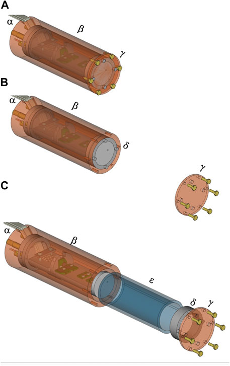
Figure 4. Drawing of the sample can (e) of Figure 3. (A): α ribbon wire cables, connected to the various braids of four twisted wires that pass through a port (i) of the top thermal shield (g) (see Figure 3), β sample can showing inside the cylinder and the sensors’ holder. γ the sample can bottom cover, which can be removed to access the cylinder inside. (B): the removal of γ allows access to δ an aluminum locking ring with four pins, which fit in the four holes drilled in the bottom cover (γ). (C): sliding the cylinder out ϵ glued to the aluminum locking ring δ.
The aluminum vacuum chamber (5A) in Figure 1 has an outer diameter of 70 mm and a wall thickness of 3 mm. Two sets of strips, made with three layers of Myoflex (Oxford Instruments), were wound around the 62-mm-diameter thermal shield for good thermal insulation from the aluminum chamber. A set of strips or spacers, about 2 cm wide, are used to ensure thermal insulation between the sample can, (e) in Figure 3, the copper rod (d1/d2), and the copper transition (c) and the top (g) and bottom (h), forming the copper thermal shield. In various parts of the system, we have used Kapton adhesive tapes and Kapton foils to fix wires and protect the wires during the insertion of the whole system shown in the right picture of Figure 3 inside the vacuum chambers (5B) and (5C) in Figure 1.
In case of pumping after 1 day from when the system is exposed to the air for servicing, installation, or exchange of a cylinder, the pressure readout of the dual Penning/Pirani gauge (8A) gives values below 10−6 mbar at room temperature and 10−8 mbar, when the coldhead reaches its minimum temperature. The pressure values are comparable for both the prototype and the upgraded system.
Temperature measurements: The temperature of the cylinder is monitored by a calibrated rhodium–iron (RhFe) sensor (Oxford Instruments), glued on a thin copper slice fixed on the bottom of the sample can with two M5 brass bolts, which is fixed with four similar bolts the cover of the sample can.
For the upgrade, another calibrated temperature sensor from Cernox (Oxford Instruments) is installed inside the cylinder on the holder of the sensors. We observed heating power released on the holder, induced by the powering of the Hall sensors. Therefore, we changed its material from Teflon, (H) in Figure 2 for the prototype, to aluminum to have better thermal conductivity between the holder of the sensors and the sample can. The renewed holder of sensors is shown in Figure 7A.
Control and data acquisition: LabView C routines and Bash scripts are used to pilot the Oxford ITC-503S heater controller, to control and record the power supply of the external magnet, to read and record pressure values via a multigauge controller (TPG256A from Pfeiffer–Balzers), to measure temperature sensor resistances via the well-known technique of four wires through a multimeter scanner (Keithley 199 System DMM/Scanner), and to acquire magnetic fields via a module (Arepoc USB2AD controller), capable of powering and controlling six Hall probes.
Thermal cycle: In the preliminary system, about 7.5 h were required to cool the sample can from room temperature to the minimum temperature, as shown in Figure 5A. Using the coldhead heater at a power of 65 W (the ITC-503S controller can supply a maximum 40 V on a resistance greater than 20 Ω, and we arranged the heater cartridges to exceed 20 Ω to fulfill the protection limit of the system), it takes about 1 hour to heat the sample can to 60 K, which is done after each test to ensure a complete transition before the next cooling for a new measurement: the trapped field should disappear at the MgB2 critical temperature (39 K). One and a half hours are needed to cool to nearly 13 K, the minimum working temperature usually before ramping the magnet down or up. We wait at least 1 hour at the desired temperature.
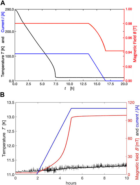
Figure 5. (A) The field cooling, or magnetization, procedure, starts from room temperature, which takes ∼ 7.5 h. After the following 5 h, the ramp down of the (
With the new system, we have decreased the mass of the copper rod connected to the second stage by reducing its diameter from 50 mm to 25 mm (d1) in Figure 3, from the flange required for the connection to the coldhead to the bottom part (d2), which remains at 50 mm in diameter, to drill pits and host the cartridge heaters. As a result, we have reduced the time to cool the system from room temperature to the minimum temperature (∼8 K), recorded by the RhFe sensor, to a little more than 3 h (see Figure 7B), compared to the 7.5 h needed for the prototype (see Figure 5A). In the upgraded system, with respect to the prototype, we also have better control over the thermalization of the whole system, thanks to the Cernox temperature sensor mounted inside the cylinder on the sensors’ holder. We must wait 1 h more to reach the lower temperature (13 K, see Figure 7B) recorded inside the cylinder, and then we can start ramping the magnet for magnetization or shielding measurements. In the prototype, we have no measurements of the temperature inside the cylinder; therefore, we wait an arbitrary 5 h longer to be certain, as shown in Figure 5A, when the ramp down of the current supplied to the magnet starts. This upgrade also reduces the time for heating to exceed the critical temperature and return to the minimum temperature. It requires between 3.5 h in the prototype, without control of the temperature inside the cylinder as aforementioned, against less than 1 h in the upgraded system with the measurements of the thermalization under the sample can, which faces the outer surface of the cylinder, thanks to the RhFe sensor, and on the sensors’ holder inside the cylinder, which faces the inner surface of the cylinder, thanks to the Cernox sensor.
This better control and monitoring was gained both on overcoming the critical temperature and on reaching the minimum, or desired, temperature.
3 Methods
To test the behaviors and the characteristics of an MgB2 cylinder, it must be inserted, sliding from the bottom between the sample can and the holder of the sensors, and connected at the bottom of the copper rod.
In the prototype system, only one Hall probe was installed in the center of the cylinder, and it was not possible to exchange the cylinder without disconnecting the wires and cables.
The upgraded system has six Hall probes, which allow mapping of the magnetic field inside the cylinder, radially and longitudinally. A temperature sensor (Cernox) is mounted to the holder. Each of these sensors requires four wires. We have used a braid of four very thin twisted wires (AWG36 size) with Teflon insulation; therefore, we organized the system to keep the cabling and wiring connected to the feed-through for the cylinder exchange operation.
The Cernox sensor is useful for monitoring the temperature seen from the inner surface of the cylinder and also for considering the sensitivity dependence on the temperature of each Hall probe, as we will show in the result of the upgraded system.
The MgB2 cylinder is axially centered with aluminum rings, and the bottom of the sample can is closed with a copper cover. The RhFe temperature sensor, which provides the temperature of the sample can, is fixed on the bottom of this copper cover. The bottom part, (h) in Figure 3, is then fixed on the top part (g) of the thermal shield, taking care to insert small tapes of indium for good thermal contacts between the connection flanges. The coldhead as a whole, shown in Figure 3 for the upgraded system, can be moved by a crane and slowly inserted in the chambers (5B) and (5A), which stay on the magnet support.
In the prototype system, the exchange of the cylinder was not possible without disconnecting all the wires, which must pass through the port (i) of the bottom part (h) of the thermal shield, then remove the RhFe sensor and finally, the bottom copper shield of the sample can. In the preliminary system, only chamber (5A) remained on the magnet support, and the coldhead (Edwards 6/30) was moved together with chamber (5B), disconnecting the bellow on the outlet of the turbo 7B. Every time we needed to work on the cylinder or inside the copper shield, we had to disconnect the sensors inside and manage the wires, which must slide through the port (i). For the upgraded system, instead, the vacuum pump and the gauge remain on the magnet because they are connected on the chamber (5B).
We used two different procedures to cool the samples to TF (the final lowest temperature, or the one set fixing proper heating of the coldhead heater), below TC, the critical temperature, and to evaluate both the trapping and the shielding capabilities of the MgB2 cylinder.
The first procedure consists of cooling the cylinder in the presence of an applied magnetic field, BC. After reaching TF, the field is slowly reduced to 0. This procedure triggers the appearance of supercurrents, trying to develop a magnetic field comparable to BC. This procedure, known as field cooling (FC), in view of our applications and interests, was named simply magnetization.
The second procedure consists of cooling the cylinder with BC equal to 0. After reaching TF, the field is slowly increased to a maximum value. In this case, the supercurrents will try to generate a magnetic field, as opposed to the external one, thus shielding its presence. This procedure, known as zero-field-cooling (ZFC), was called simply shielding.
We had evidence of both behaviors already in the preliminary studies, which we recall here as a starting point to have clearer evidence and a better interpretation of the observed behavior in the upgraded system with more sensors installed inside the cylinder.
3.1 Feasibility studies on the prototype system for tuning the experimental methods
For the magnetization procedure, the cylinder is placed in a transverse (with respect to the symmetry axis of the cylinder) magnetic field, produced by the standard dipole magnet, then cooled to the temperature TF (the minimum reachable, or a set one, to be obtained by properly tuning the coldhead heater). Meanwhile, the external magnet BC is kept constant (980 mT) by keeping the current (110 A) supplied to the magnet constant.
The system is kept for a sufficient time at the minimum temperature to be sure that the whole cylinder is thermalized. This blindness to the temperature inside the cylinder caused us to upgrade the system with the Cernox temperature sensor mounted on the holder of sensors.
Afterward, the magnetic field is ramped down slowly enough to allow the supercurrents to follow its change. We chose 0.01 A s−1 at the beginning as the timing for the ramp up of the current supplied to the magnet, which became a standard for our next tests, at least as a starting point at the installation of new cylinders.
We have observed good performance also decreasing the ramp time, which we have followed after obtaining good performance using our standard timing.
In the shielding procedure, the cylinder, at a temperature higher than TC, is kept in BC equal to 0 and cooled in this condition. After sufficient time for the thermalization, we ramp up the external magnet at the same time at 0.01 A s−1.
The behaviors observed in the preliminary studies with a single Hall probe in the center of the cylinder and in the middle of its length are quite clear and have become a reference for the further detailed measurements of six Hall probes installed inside the cylinder for the subsequent studies after the upgrade.
A typical trapped field cycle in the case of the magnetization procedure for the preliminary study is shown in Figure 5A. With an external field of 980 mT, the sample is cooled from room temperature, or from a temperature higher than TC, to the minimum reachable temperature or a temperature set below TC. After the system is stabilized at this temperature, the external field is ramped down to a current equal to 0 while the residual field of the MgB2 cylinder is measured.
In Figure 5A for the prototype system, starting from an applied external field of 980 mT, with a current of 110 A, after ramping down the current supplied to the magnet to 0, with a time rate of 0.01 A s−1, the trapped field, measured in the center and in the middle of the cylinder, remains at 942 mT. The trapped field was preserved for 6 days (and was only stopped so that we could perform other measurements) at the temperature of 13 K, unless a rise in temperature appears, in the order of a few K, which can reduce the trapped field drastically. These temperature increases were recorded by the RhFe sensor, connected under the sample can, and are due to thermal cycles in the coldhead, which can be listened to and recorded by a microphone. These instabilities were observed with the Edwards 6/30 coldhead every 2.5 h in synchrony with the changes in the thermal cycle of the He compressor. We could not solve the problem, and the company producing the system was not able to give us a solution for the system in use.
With the feasibility study system, we could investigate other topics that are of interest for our applications and also properly design the system upgrade.
Moving the MgB2 cylinder: The planned scheme for using an MgB2 magnet and shield, after its preparation, requires its transportation into experimental apparatuses or facilities. Trial moves were performed: the vacuum chamber containing the MgB2 cylinder and its vacuum systems were removed from the magnet by a crane, and the coldhead was connected and in functioning mode during the movements. The trapped field was maintained during removal and returned to its position with no detectable field losses [13].
ZC and ZFC cooling at different temperatures: The feasibility studies on the prototype cylinder have provided promising results for the ZC, magnetization, and the ZFC, shielding, procedures. We were able to investigate FC and ZFC behaviors of the test cylinder at different temperatures TF, properly setting the heating power on the heating collar clamped on the second stage, (L) in Figure 2.
In Figure 6 we report new results on the field trapped in the magnetization procedure and the shielded field, obtained by subtracting the recorded penetrating fields from the externally applied fields in the shielding procedure, even though the feedback and control of the temperature were not comfortable because the heaters, (L) in Figure 2, were clamped on the second stage of the coldhead. Therefore, they required 3.5 h to reach stability after setting a new temperature point. These experiences guided us to move the heaters as close as possible to the sample can at the bottom of the copper rod, (d2) in Figure 3, and to lower its mass, reducing its diameter as shown in its part (d1) in Figure 3, in the upgrade. We reduced the time required to measure a new point, which for the upgraded system was 1 h. Because the values of the trapped and shielded fields depend on temperature, more stable and lower temperatures are required, which will be accomplished with the new coldhead.
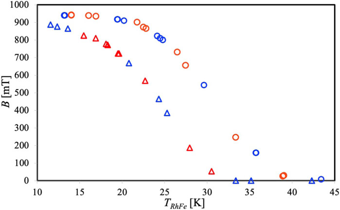
Figure 6. Trapped field measurements (
More clear evidence from Figure 6 is that the cylinder can maintain more supercurrents (or generate a higher magnetic field) in the FC procedure than in the ZFC (or shield the less magnetic field) one. In addition, it is evident in Figure 6 that for the trapped fields in the FC procedure, we reach the saturation (plateau) at a higher temperature TF than for the shielded field in the ZFC procedure. These observations also brought us to look for coldheads that can reach lower temperatures.
3.2 Details on solutions adopted in the upgraded system
We exploited the opportunity to upgrade our system to host a new coldhead (RDK-415D from SHI Cryogenics Group), available from our collaborators [6], with a nominal temperature of 40 K and a cooling power in the range of 42 W on the first stage and 4 K and 1.8 W on the second stage.
The changes shown in Figure 3 have been required to match the new coldhead geometry to the existing vacuum chambers (5A) and (5B) and to the sample can geometry and copper rod, at least to have the chance to return to the preliminary prototype. The copper shield has been renewed and redesigned in two parts: (h) in Figure 3 the bottom part with the same geometry as the previous one, (D) in Figure 2, and (g) a new top part in Figure 3, which can be connected to the bottom part and to the first stage (a) of the new coldhead. This top part (g) is equipped with two access ports: one is visible in Figure 3 under the transparent drawing of the chamber (5C) and the second one is located on the opposite side. These two access ports on the top part (g) are similar to the one (i) on the bottom part (h). These two ports are required as feed-throughs for the cabling and wiring of the sensors mounted on the holder, which fit inside the cylinder (f) and are connected inside and on the top of the sample can (e).
The new system is designed in such a way that it is possible to return to the preliminary feasibility study system. The new sample can (e), together with the new copper rod (d1/d2) and the bottom part (h) of the copper shield, can be connected respectively to the second and first stages of the previous Edwards 6/30 coldhead, (A) in Figure 2. We have in hand the spare parts, and by modifying the old copper rod, (E) in Figure 2, to match the new one, (d1/d2) in Figure 3, we can use them in another vacuum chamber to test sensors, new ideas, and designs, and then implement them in the system in use, which will be operating for systematic studies of different cylinders.
One of the innovative solutions of the upgraded system is the possibility of exchanging the cylinders without removing the cabling and wiring of the Hall and temperature sensors on the vacuum side. Once the vacuum is broken and the three sensor connectors from the air side are disconnected, the whole assembly shown on the right of Figure 3 can be removed by a crane. In the air, the bottom part (h) of the thermal shield can be removed, then access to the sample can, (e) in Figure 3, and easily remove the cylinder following the sequence shown in Figure 4.
In the new sample, more sensors can be installed inside the cylinder on the holder of the sensors, shown as a drawing and as a picture in Figure 7A, to measure the magnetic field in the center and in a radial position with respect to its symmetry axis, and on its middle and on its edge along the symmetry axis. To distinguish between the sensors, we label them with subscript numbers and acronyms. We use different colors and different styles for lines, which we adopted for the plotting, as shown in Figure 7A. In the following, we explain their meaning:
(⋅ ⋅) S1 mcl, where “mcl” means middle–central–longitudinal: this probe is in the middle with respect to the length of the cylinder along its symmetry axis, in the center with respect to the radial coordinate orthogonal to the symmetry axis, and it is mounted in the way to monitor and measure longitudinal magnetic fields;
(
(
(—) S4 ect, where “ect” means edge– central–transverse, where the new term means that the probe is on the edge of the cylinder along the longitudinal symmetry axis;
(
(
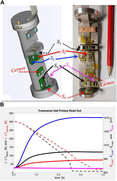
Figure 7. (A) New holder of sensors: drawing (left) and picture (right). Hall probes for transverse, (
The couple
Figure 7A shows a drawing on the left and a picture on the right of the realized holder of sensors, with the labels assigned to the Hall probes and the Cernox temperature sensor connected to the holder.
The Cernox sensor provides information on the temperature, seen from the inner surface of the cylinder, and then gives the measure of the time needed for thermalization of the whole system. The copper cover of the sample can, shown with its bolts in the left side of Figure 3, can be removed as shown in Figure 4 with the possibility of exchanging cylinders without removing the delicate connections of the Hall probes and the Cernox sensor, shown in their compactness with their delicate connections in the picture on the right of Figure 7A.
4 Results and discussion
We report the results from the commissioning of the upgraded system, satisfying the following requirements: working in a 1 T magnetic field range of the recombination of an atomic polarized beam in hyper-polarized molecules [6], controlling the temperature to find the best working conditions, and being stable for 6 or more days. The autogenerated field is sufficient to keep the polarization; if it is prepared in the recombination system at 1 T, it maintains a field higher than 300/400 mT. The mapping of the field inside the cylinder allows us to choose where to properly locate the condensing surface for the polarized substances or, in the case of its use of a polarized nuclear target, how to scale the target dimension or the cylinder geometry to fulfill the requirements still under design [7].
One of the first proofs is the dependence on temperature of the sensitivity of the Hall probes, as shown in Figure 7B.
The sensors we have installed are calibrated at a temperature of 297 K. The dependency of Hall probes on the temperature is well known, as reported in the literature [19] for the same types of installations. We must correct the raw data acquired by the Arepoc controller: a sixth-order polynomial fit is applied to the corresponding data acquired using the calibration at 297 K in the function of the temperature TCernox. We then must be sure that the cooling starts from a temperature higher than 297 K because around this temperature, the variation is bigger (see Figure 7B). As a result, the installation of the Cernox sensor on the holder of the sensors has been mandatory for the temperature corrections and is not only useful for monitoring the temperature difference between the outer and inner surfaces of the cylinder.
The improvement in the cooling time is evident from the comparison of Figure 5A, in which ∼ 7.5 h are required to reach the minimum temperature of the RhFe readout, starting from a temperature higher than 297 K, instead of a little bit more than 3 hours in Figure 8A for the new system. In both cases, the RhFe sensor made good thermal contact with the bottom of the sample can.
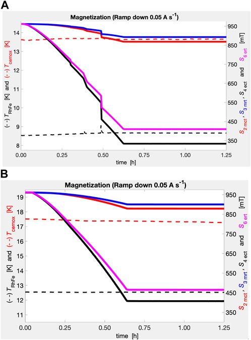
Figure 8. Upgraded system. Respective trapped fields for magnetization from 110 A (960 mT) with a ramp down of 0.05 A s−1 (A) at the lowest temperature (TRhFe ∼ 8.5 K, TCernox ∼13.7 K): (
One more advantage is that in the preliminary system, we were not able to monitor when the inner surface neared the minimum temperature. In the upgraded system, this is monitored by the Cernox sensor, and it takes a little more than 4 hours, 1 hour more than the time required to reach the minimum temperature on the bottom of the sample can. In the preliminary system, we had to wait an arbitrary time because we were not sure about the thermalization of the inner part inside the cylinder. Figure 5A shows that we waited more than 5 h after the RhFe sensor read the minimum temperature to be sure of the cooling of the whole MgB2 cylinder, and only then did we start to ramp down the current supplied to the magnet for the FC procedure or ramp for the ZFC procedure.
To move to another measurement, we must heat the cylinder and overcome the critical temperature, observing the transition of it from the superconducting state to the normal one. The sample can warm earlier than the sensors’ holder, and in the magnetization case, we observed that the trapped field is completely lost only when the Cernox temperature is higher than 39 K. The parts of the cylinder that are still below the critical temperature can run supercurrents, but they are reduced as the temperature increases.
In summary, we report the main achievements of the upgraded system in comparison with the feasibility study system in Table 1, thanks to the experience gained with it.
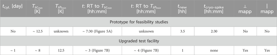
Table 1. Comparison between the prototype and upgraded system: tcyl: time required to exchange a cylinder,
For the commissioning of the system, we have inserted an MgB2 cylinder prepared with boron grains having a maximum size of 40 μm, P40, with a length of 97.0 mm and an inner and outer diameter, respectively, of 32.5 mm and 38.5 mm in the sample can. The P40 is more unstable but can support higher super currents (Giunchi, 2016); therefore, it is a good test to monitor the sensitivity of our system to instabilities that can be overcome at higher temperatures. In Figure 8A, the values, calibrated and corrected with their respective temperature sensitivities, of the four sensors that monitor the transverse magnetic fields inside the cylinder, are reported for the magnetization procedure. The system is sensitive to flux jumps: three flux jumps are recorded at the lower temperature of the FC procedure (8.5 K on the bottom of the sample can), which are more evident on the Hall probes S4 ect and S6 ert located on the edge of the cylinder. The flux jumps are also recorded by the middle probes, S2 mct and S3 mrt, where the transverse field losses are much less.
As shown in Figures 8A, B the probes measure higher fields close to the wall of the cylinder, radial probes S3 mrt in the middle and S6 ert on the edge, with respect to the probes in the center of the symmetry axis, S2 mct in the middle and S4 ect on the edge. In addition, higher magnetic fields are observed in the middle than on the edge of the cylinder, along the central position S2 mct, at the middle vs. S4 ect at the edge, and along the radial position S3 mrt at middle vs. S6 ert at the edge.
The system allows us to monitor the behavior of the fields with respect to the temperature. We could control the flux jumps by increasing the temperature. For the sample P40 under study, we could follow the number of flux jumps from three to two, to one and finally to zero. In Figure 8B, at a temperature recorded by the RhFe on the bottom of the sample can of 12.5 K, the case without flux jumps is evident, in which the trapped magnetic field was higher than in the case of three flux jumps at the lowest temperature of Figure 8A.
The commissioning of the upgraded system fulfills the requirements for investigating the behavior of a transverse magnetic field along the longitudinal direction, which is the symmetry axis of the geometry under study, of a hollow cylinder, and also radially, giving the possibility to provide the mapping and also the homogeneity of the field for use as a holding and transportation field for nuclear-polarized substances.
Table 2 reports the quantities that can be recorded, allowing the characterization of the MgB2, showing the capabilities of the system in investigating the behavior of the superconductor bulk material at a set temperature, acquiring the distribution of the magnetic field, and recording its values. The spatial variation of the field can be provided along the radial coordinate in the middle, for example, (ΔB/Δr)m= (
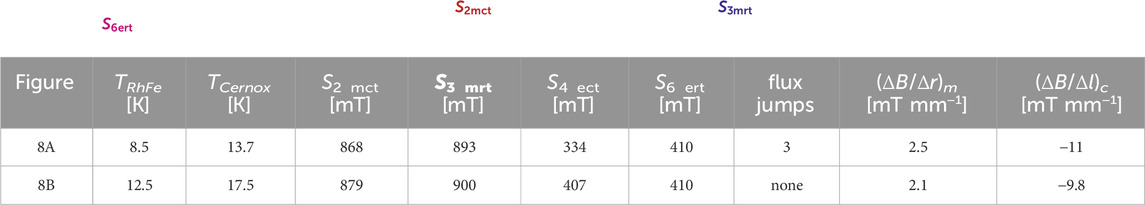
Table 2. Comparison of two magnetization procedures from the respective figures. TRhFe: temperature under sample can, TCernox: temperature on the sensors’ holder. Transverse magnetic field inside the cylinder:
5 Conclusion
Thanks to the experiences gained in preliminary feasibility studies on a hollow bulk superconducting MgB2 cylinder, an upgraded system that allows testing different production procedures has been redesigned and commissioned to allow easy cylinder exchange and mapping of the magnetic field inside them.
This dedicated apparatus allows us to investigate the possible exploitation of bulk MgB2 in the production and transport of polarized fuel in future nuclear fusion facilities.
After a series of modifications and improvements from the initial design, the apparatus has been successfully commissioned and is ready for proper characterization of high-temperature superconducting materials in a cylindrical form, which fits the geometry of an inner diameter greater than 30.0 mm, an outer diameter less than 38.7 mm, and a maximum length of 116 mm.
The requirements for nuclear fusion fuels have already been fulfilled in the commissioning work with a P40 cylinder, which is not, according to the literature, the best-performing one, at least for its stability. However, it has shown good behavior in the field of 1 T, perfectly tuned with the polarized atomic beam recombination apparatus [6] and provided autofields sufficient to maintain nuclear polarization in the molecules. In the future, different samples with different grain sizes will be systematically characterized, with different thicknesses and different geometry, tapered cylinders with a thicker wall at the edges, for instance, to find the best solution, which means higher fields, higher stability, good homogeneity, and less bulk material, which means thinner cylinder walls.
Data availability statement
The raw data supporting the conclusion of this article will be made available by the authors, without undue reservation.
Author contributions
GC: conceptualization, data curation, formal analysis, funding acquisition, investigation, methodology, project administration, resources, software, supervision, validation, visualization, writing–original draft, and writing–review and editing. LB: data curation, investigation, methodology, software, and writing–review and editing. MC: funding acquisition and writing–review and editing. LDB: investigation and writing–review and editing. PL: funding acquisition and writing–review and editing. FS: validation, writing–review and editing, conceptualization, and formal analysis. MS: methodology, writing–review and editing, conceptualization, and investigation. GT: software, data curation, and writing–review and editing.
Funding
The author(s) declare that financial support was received for the research, authorship, and/or publication of this article. The project is funded by the PS-INFN-Energia (Progetto Speciale dell᾽Istituto Nazionale di Fisica Nucleare) under the PolFusion project and the Nuclear Physics Committee III of the INFN under the Project CLAS12.
Acknowledgments
We acknowledge the PS (Progetto Speciale; in English, special project) INFN energia for their support in the field of nuclear fusion via the PolFusion collaboration, the University of Ferrara, which supports the PREFER collaboration and hosts the apparatus in the Heavy Experiments Hall in conjunction with the INFN division of Ferrara, and the LASA–INFN–Milano division, for their collaboration and the work in progress for future tests with longitudinal magnetic fields. We also acknowledge our mechanical workshop for their contributions to the design, realization, and modifications on the apparatuses, mainly the technicians M. Cavallina, S. Squerzanti, and technologist A. Saputi. We acknowledge the Institut für Kernphysik (IKP) of the Forschungszentrum of Jülich for the loan of the new coldhead for the duration of this work.
Conflict of interest
The authors declare that the research was conducted in the absence of any commercial or financial relationships that could be construed as a potential conflict of interest.
Publisher’s note
All claims expressed in this article are solely those of the authors and do not necessarily represent those of their affiliated organizations, or those of the publisher, the editors, and the reviewers. Any product that may be evaluated in this article, or claim that may be made by its manufacturer, is not guaranteed or endorsed by the publisher.
References
1. Ciullo G. Polarized fusion: an idea more than thirty years old! what are we waiting for? In: G Ciullo, R Engels, M Büscher, and A Vasilyev, editors. Nuclear fusion with polarized fuel. Switzerland: Springer International Publishing (2016). 1–13. doi:10.1007/978-3-319-39471-8_1
2. Kulsrud RM, Furth HP, Valeo EJ, Goldhaber M. Fusion reactor plasmas with polarized nuclei. Phys Rev Lett (1982) 49:1248–51. doi:10.1103/PhysRevLett.49.1248
3. Kulsrud RM, Valeo EJ, Cowley SC. Physics of spin–polarized plasmas. Nucl Fus (1986) 29:1443–62. doi:10.1088/0029-5515/26/11/001
4. More RM. Nuclear spin-polarized fuel in inertial fusion. Phys Rev Lett (1983) 51:396–9. doi:10.1103/PhysRevLett.51.396
5. Leemann C, Bürgisser H, Huber P, Rohrer U, Schieck HP, Seiler F. Investigation of the 3
6. Engels R, Grigoryev K, Kannis CS, Michael Y, Ströher H, Verhoeven V, et al. Production of HD molecules in definite hyperfine substates. Phys Rev Lett (2020) 124:113003–1/5. doi:10.1103/PhysRevLett.124.113003
7. Carman DS, Burkert V, Elouadrhiri L. The CLAS12 spectrometer in hall b at jefferson laboratory. Nucl Instr Meth A (2020) 967:163898. doi:10.1016/j.nima.2020.163898
8. Frankel DJ. Model for flux trapping and shielding by tubular superconducting samples in transverse fields. IEEE Trans Magn (1979) 15:1349–53. doi:10.1109/TMAG.1979.1060310
9. Fagnard JF, Elschner S, Hobl A, Bock J, Vanderheyden B, Vanderbemden P. Magnetic shielding properties of a superconducting hollow cylinder containing slits: modelling and experiment. Supercond Sci Technol (2012) 25:104006. doi:10.1088/0953-2048/25/10/104006
10. Statera M, Contalbrigo M, Ciullo G, Lenisa P, Lowry M, Sandorfi A. A bulk superconducting magnetic system for the CLAS12 target at Jefferson Lab. IEEE Trans Appl Supercond (2015) 25:1–4. doi:10.1109/TASC.2015.2388855
11. Rabbers JJ, Oomen MP, Bassani E, Ripamonti G, Giunchi G. Magnetic shielding capability of MgB2 cylinders. Supercond Sci Technol (2010) 23:125003. doi:10.1088/0953-2048/23/12/125003
12. Giunchi G, Ceresara S. Method for the preparation of highly densified superconductor massive bodies of MgB2, relevant solid end–products and their use. Italy: Edison Italian – Pat. Appl. N. MI2001A0978 (2001).
13. Statera M, Balossino I, Barion L, Ciullo G, Contalbrigo M, Lenisa P, et al. A bulk superconducting MgB2 cylinder for holding transversely polarized targets. Nucl Instr Meth A (2018) 882:17–21. doi:10.1016/j.nima.2017.10.051
14. Giunchi G. High density MgB2 obtained by reactive Liquid Mg infiltration. Int J Mod Phys B (2003) 17:453–60. doi:10.1142/s0217979203016091
15. Nagamatsu J, Nakagawa N, Muranaka T, Zwnitaniana Y, Akimitsu J. Superconductivity at 39 K in magnesium diboride. Nature (2001) 410:63–4. doi:10.1038/35065039
16. Canfield P, Finnemore D, Bud’dko S, Ostenson J, Lapertot G, Cunninghan C, et al. Superconductivity in dense MgB2 wires. Phys Rev Lett (2001) 86:2423–6. doi:10.1103/PhysRevLett.86.2423
17. Giunchi G. The Reactive Liquid Infiltration technique for the bulk reaction of MgB2. In: R Flükiger, editor. MgB2superconducting wires – Basics and applications. Singapore: World Scientific Publishing Co. Pte. Ltd. (2016). p. 159–208.
18. Engels R. Loan of the cold–head and cryodrive unit from – Forschungszentrum Jülich – Germany (2020).
Keywords: nuclear polarization, fusion with polarized fuel, superconducting magnets, MgB2, superconductors
Citation: Ciullo G, Barion L, Contalbrigo M, Del Bianco L, Lenisa P, Spizzo F, Statera M and Tagliente G (2024) Bulk superconducting materials as a tool for control, confinement, and accumulation of polarized substances: the case of MgB2. Front. Phys. 12:1358369. doi: 10.3389/fphy.2024.1358369
Received: 19 December 2023; Accepted: 05 March 2024;
Published: 17 April 2024.
Edited by:
Liangliang Ji, Chinese Academy of Sciences (CAS), ChinaReviewed by:
Jean-Pierre Didelez, UMR9012 Laboratoire de Physique des 2 infinis Irène Joliot-Curie (IJCLab), FranceSairam Geethanath, Johns Hopkins University, United States
Copyright © 2024 Ciullo, Barion, Contalbrigo, Del Bianco, Lenisa, Spizzo, Statera and Tagliente. This is an open-access article distributed under the terms of the Creative Commons Attribution License (CC BY). The use, distribution or reproduction in other forums is permitted, provided the original author(s) and the copyright owner(s) are credited and that the original publication in this journal is cited, in accordance with accepted academic practice. No use, distribution or reproduction is permitted which does not comply with these terms.
*Correspondence: G. Ciullo, ciullo@fe.infn.it