Design of a kilohertz repetition rate, low-emittance S-band photoinjector
 Tianhui He
  Lijun Shan Hanbin Wang Dexin Xiao Kui Zhou Peng Li Jianxin Wang
  Hanxun Xu*
  Zheng Zhou* Ming Li
  Dai Wu
- Institute of Applied Electronics, China Academy of Engineering Physics, Mianyang, China
Low-emittance photoinjector-enabled cutting-edge scientific instruments, such as free-electron lasers, inverse Compton scattering light sources, and ultrafast electron diffraction, will greatly benefit from the improved repetition rate. In this paper, we proposed a specifically designed S-band radio frequency (RF) photoinjector to obtain low emittance and kilohertz (kHz) high-repetition rates simultaneously. By lowering the gradient, much lower RF power is needed to feed the electron gun, and then the heat problem is much easier to handle. Meanwhile, by optimizing the length of the gun’s first cell from the normal case of 0.6-cell to 0.4-cell, the launch phase and the extraction field are significantly improved, thus ensuring the generation of low-emittance electron beams. In our design, the proposed 1.4-cell RF gun can work effectively under different field gradients ranging from 30 MV/m to 100 MV/m. For a standard case of 60 MV/m, 2.5 MW peak RF power with μs level pulse width is sufficient, thus offering the feasibility of improving the repetition rate to kHz level with a standard 5 MW irradiation klystron. In addition, simulated electron beams with a low emittance of 0.29 mm.mrad@200 pC can be generated by this proposed photoinjector, showing that this high-repetition rate injector holds the potential to deliver high-quality beams comparable to those of state-of-the-art S-band photoinjectors. Combining the merits of low emittance and high-repetition rate, this proposed photoinjector will provide a new possibility for future free-electron laser facilities operating at repetition rates ranging from kHz to tens of kHz.
1 Introduction
In the past 2 decades, S-band photocathode radio frequency (RF) gun-based low-emittance photoinjectors [1] have successfully driven advanced light sources, such as free electron lasers and inverse Compton scattering light sources. In these applications, electron beams with high bunch charge and low emittance are required. To achieve this goal, intensive R&D efforts have been devoted to the design and optimization of S-band photocathode RF guns [2–6], and ground-breaking technical advances have been achieved. Represented by the famous BNL/SLAC/UCLA type [7], the mature S-band RF gun can work on a high gradient of 100–140 MV/m. Furthermore, the first cell length is optimized to 0.6 times half of a wavelength λRF (often referred to as 0.6-cell) in order to provide stronger RF focusing on nC-level high bunch charge beams. With appropriate driving laser parameters and emittance compensation setup [8], the 1.6-cell S-band RF gun can generate high-quality electron beams with a low emittance of 1 mm.mrad at a standard bunch charge of 1 nC [9]. However, limited by the heat problem, as most of the RF power is consumed on the wall, the typical repetition rate of the S-band photoinjector is 10–100 Hz, and the duty factor is below 0.1% [10]. With specifically designed cooling channels surrounding the cavity, a 1.5-cell S-band RF gun with up to 400 Hz repetition rate has been developed at CLARA [11].
Nowadays, since a wide range of scientific experiments will benefit from increasing the repetition rate of X-ray pulses, high-duty factor photoinjectors have drawn worldwide interest in driving high-flux-free electron laser facilities. The repetition rate of these high-duty factor photoinjectors is up to MHz, while the bunch charge varies from tens to a few hundreds of pC [12], instead of nC level in low-duty factor photoinjectors. To fulfill these requirements, different types of high-duty factor photo guns have been explored [13] in-depth, including DC guns, normal-conducting low-frequency RF guns, and super-conducting RF guns. For any of the abovementioned guns, either simulated or measured emittance is good enough for efficient lasing, though its gradient is much lower than that of an S-band RF gun. This phenomenon reveals the possibility that we can significantly improve the duty factor of existing S-band photoinjectors by lowering the gun gradient, since the RF power drops quadratically with the gradient. If realized, this high-duty factor photoinjector would fill up the huge gap between current S-band photoinjectors and on-going MHz repetition rate photoinjectors. We note that a kHz high-repetition rate C-band injector is being developed at the Frascati National Laboratory [14]. However, a high-power RF source is still beyond the reach of this high-repetition rate, high-gradient (160–180 MV/m) C-band photocathode RF gun.
In this paper, we investigated the feasibility of the S-band photoinjector with a kHz repetition rate and low emittance on the basis of using mature S-band irradiation klystrons. First, we will give a detailed description of the physics underlying the simultaneous achievement of a high-repetition rate and low emittance. Then, the design of the special S-band RF gun will be introduced. In the following section, the whole injector beamline design will be shown, together with the beam dynamics simulations using the bench-marked code. In the last section, we will provide discussion and conclusion.
2 Methodology to obtain a high-repetition rate and low emittance
In photoinjectors, the quality of electron beams is often evaluated by the concept of beam brightness B, which integrates several independent parameters such as bunch charge Q, transverse emittance ϵn,r, and bunch duration σt. Previous research [15] has pointed out that the five-dimensional beam brightness B is finally determined by the RF gun conditions [16] as follows:
where I = Q/σt is the beam current, Eg is the gun gradient, and ϕ0 is the cavity phase when the driving laser illuminates on the photocathode, which is also referred to as the launch phase. Then, the product Eg sin (ϕo) stands for the extracting field strength at the launch phase. Obviously, Eq.1 implies that one can access brighter electron beams by improving the extracting field.
As to the commonly used 1.6-cell S-band RF gun, the standard gun gradient is approximately 100 MV/m. Although the gradient is high enough, the elongated first cell length leads to a relatively small launch phase of 30° to obtain maximum energy gain. In practice, this launch phase is set to 26° for optimal emittance compensation results. On this occasion, the extracting field is only 50 MV/m, which is much lower than the gun gradient.
It is notable that by significantly increasing the launch phase, one can take full advantage of the high-gradient RF gun and obtain ultimate beam brightness. P. Musumeci et al. developed a novel 1.4-cell high-gradient gun to maximize beam brightness [17]. The key physics is to obtain a much higher launch phase by shortening the initial cell length, where phase slippage in the initial cell due to electron velocity smaller than the light speed can be greatly diminished. As shown in Figure 1, the launch phase for the 1.4-cell gun at a gradient of 100 MV/m has improved to 70°, and the extracting field reaches 94 MV/m, which is 1.88 times that in the 1.6-cell gun. Although weaker RF focusing in a 1.4-cell gun makes it more difficult to compensate the transverse emittance for nC-level high-charge electron beams, this problem would be less important in high-duty factor photoinjectors, as the bunch charge decreases to tens or a few hundreds of pC. Especially in the case of ultrafast electron diffraction (UED), the issue can be fully ignored since only tens of fC to pC bunch charge is required and emittance compensation is of less significance. F. Kuan et al [18] applied this idea to UED use and proved that smaller transverse emittance and shorter bunch duration can be generated by the 1.4-cell gun than the 1.6-cell gun. Then, higher spatio-temporal resolution can be expected.
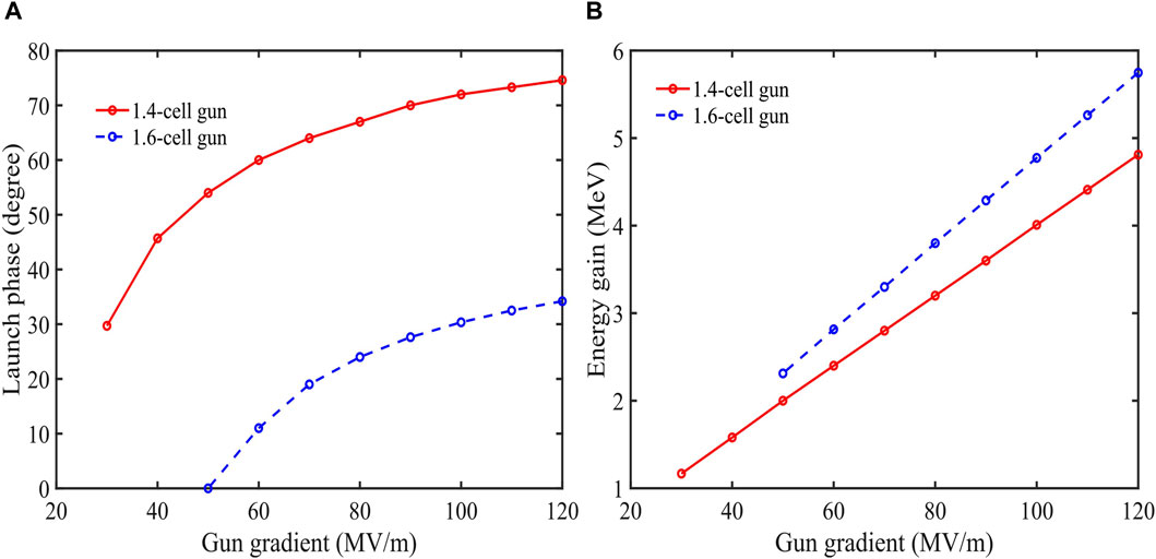
Figure 1. Comparison between 1.4-cell and 1.6-cell gun: (A) launch phase and (B) energy gain at different gradients. Note, the launch phase in (A) refers, in particular, to the phase when energy gain is highest.
In our design, the merits of the 1.4-cell gun design are further explored. Though the standard 100 MV/m gun is available in several famous accelerator laboratories, the whole process (including gun design, materials, machining, welding, cold tests, and high power tests) is still difficult for beginners or less experienced laboratories. Therefore, we put forward a new path that is uses a low-gradient 1.4-cell gun. Since the 1.4-cell gun can increase the launch phase by approximately 40° (Figure 1) at the same gradient when compared to the 1.6-cell gun, there exists a possibility that one can obtain high-brightness electron beams at a relatively low gradient. For example, when the 1.4-cell gun works on the 60 MV/m gradient, the launch phase is near 60° and the extracting field reaches 52 MV/m, which is still higher than that of the 1.6-cell gun at 100 MV/m.
More importantly, much lower RF power is needed for the lower gun gradient since the total RF power
As to the real engineering design, the key point is to design a 1.4-cell gun that can bear the excessive heat. Compared with the conventional high-gradient S-band 1.6-cell gun, a tenfold improvement in the repetition rate of this 1.4-cell gun at 60 MV/m brings a fourfold heat load, thus requiring a more complicated cooling system. Fortunately, the success of the L-band normal-conducting RF gun [19, 20] in long macro pulse mode provides a perfect case study for designing this high-duty factor, high-repetition rate S-band RF gun.
3 RF gun design
Before starting the RF gun design, the basic gun shape chooses the coaxial RF coupling type instead of the most commonly used side coupling in S-band RF guns. One reason is for the convenience of designing complicated cooling channels by removing the side coupling waveguide. Another reason is for a more flexible emittance compensation setup where the gun solenoid surrounding the gun cavity can be freely located as the beam dynamics require. Aiming at the kHz high-repetition rate, the primary goal of the gun RF design is to minimize the power needed at a standard gradient of 60 MV/m.
The developed RF gun is a typical standing-wave resonant cavity working at the π mode at 2,856 MHz. The initial cell length is fixed to 0.4∗λRF/2 = 21 mm to fulfill the 0.4-cell shape requirement, where λRF = 10.5 cm is the RF wavelength. To alleviate the thermal effect at a high-repetition rate, the iris tip is optimized to an elliptical shape for lowering the maximum surface field. Cell rounding is applied to the outer walls of the cavity cells to reduce the required RF input power, as shown in Figure 2A. A door-knob coaxial coupler is designed to feed the RF power while mitigating the higher-order electromagnetic modes caused by the deterioration of the azimuthal cavity symmetry. The distribution of the electromagnetic fields is shown in Figure 3, and the calculated RF parameters are listed in Table 1. This gun is designed to work with a peak field of Eg = 60 MV/m at the cathode surface, which corresponds to a required RF input power of 2.5 MW. The maximum surface field is optimized to 1.04 Eg, and the field balance between the full cell and half-cell is adjusted to 0.98. The working frequency is tuned to 2,856.0 MHz with a 10.94 MHz frequency spacing to the 0 mode. Both the cavity body and coaxial coupler are made of oxygen-free copper, and the quality factor of π mode is 12,413. The coupling factor of the coupler is tuned to 1.02 considering the beam loading under working conditions.
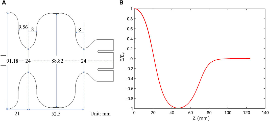
Figure 2. Gun cavity shape (A) and the normalized acceleration field distribution on the axis (B).
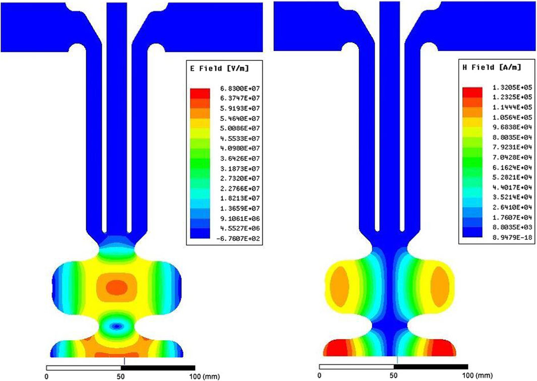
Figure 3. Distribution of the electric field (left) and the magnetic field (right).
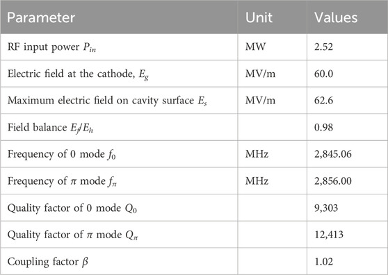
Table 1. RF parameters of the 1.4-cell gun.
In this case, when the RF pulse width is 2 μs and the repetition rate is 1 kHz, the maximum heat dissipated in this RF gun is 5 kW. Taking the CLARA gun as a referee, its heat load is approximately 6.8 kW and leads to a steady-state temperature increase of 14°C when using nine cooling channels [11]. Therefore, when using a similar cooling system design, the heat problem at the kHz repetition rate can be easily addressed.
4 Whole injector design
4.1 Layout
The layout of the proposed kHz S-band photoinjector is almost identical to existing ones, as shown in Figure 4. Electron beams are generated by the laser illuminating the metal or semi-conductor photocathode. A solenoid surrounding the gun (marked as Sol-1) is used for emittance compensation. At the beam waist position downstream of the gun solenoid, a 3-m-long SLAC-type traveling wave accelerator is used to boost the beam energy to a few tens of MeV. An additional focusing solenoid (marked as Sol-2) is placed outside the first 1/3 part of the accelerator, which is to provide better control of the beam envelope inside the accelerator. Once the so-called matching condition is satisfied (i.e., the beam envelope forms a waist and emittance reaches a local maximum at the entrance of the accelerator), emittance oscillations will be damped to a final value at relativistic energy, which is generally higher than 100 MeV. For simplicity, only one acceleration tube is used.

Figure 4. High-repetition rate S-band photoinjector layout (not to scale).
4.2 Beam dynamics simulation
Based on the above photoinjector layout, beam dynamics simulations via ASTRA code [21] were carried out to evaluate the beam brightness performance. In the following simulations, the bunch charge is set to 200 pC, while the gun gradient is set to 60 MV/m. The optimization process is also similar to the conventional S-band photoinjector, where multiple parameters, including laser initial dimensions and distributions, solenoid focusing strength, and accelerator position, are scanned. For saving time, a single objective genetic algorithm is utilized to accelerate the whole optimization process.
Since the energy gain at the exit of our 1.4-cell gun is only 2.3 MeV, while this value is 4.7 MeV in a 100 MV/m high-gradient 1.6-cell gun, the length of the gun solenoid is found to be very sensitive to the minimum transverse emittance. This is because the existence of a high-order field in the solenoid leads to non-linear focusing of the beam slice and then causes emittance growth [22]. Therefore, several gun solenoids with different longitudinal dimensions are designed to mitigate the spherical aberration of the gun solenoid. After optimization, the optimal physical length of the gun solenoid is set to approximately 10 cm, which is only half of the conventional 1.6-cell gun solenoid. In addition, the location of the accelerator is much closer to the gun in our design, which is only 0.8 m. For contrast, the first booster is often placed 1.5 m downstream of the high-gradient 1.6-cell gun. In this sense, using a 1.4-cell low-gradient gun can make a compact photoinjector. The optimized electrical and magnetic field distribution along the beamline is shown in Figure 5. The detailed parameters used in beam dynamics simulations after optimization are listed in Table 2.
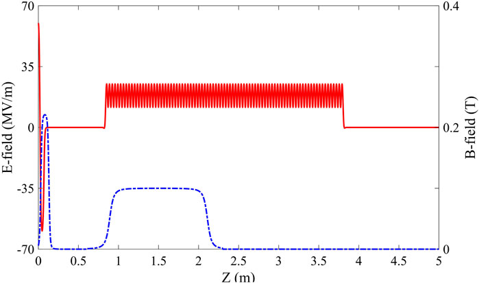
Figure 5. Optimized electrical field distribution (red solid line) and magnetic field distribution (blue dashed line).
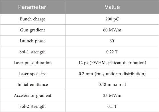
Table 2. Parameters of beam dynamics simulation.
The optimized emittance compensation results are shown in Figure 6. As we can see, after suitable focusing of the solenoid, matched electron beams are injected into the booster, and the transverse emittance is damped to 0.29 mm.mrad. This emittance compensation result is on the same level when compared with an existing high-gradient gun-based photoinjector, where 0.35 mm.mrad low emittance can be obtained at 200 pC bunch charge [23, 24]. In the longitudinal aspect, due to a relatively high launch phase, rather weak longitudinal focusing is provided to counter the space charge force-induced pulse lengthening. Therefore, the final bunch length is compressed to approximately 15 ps (full width at half maximum, FWHM), which is a little bit longer than the initial laser pulse of 12 ps FWHM. Substituting these results into Eq.1, we can find that the beam brightness generated by this 1.4-cell gun-based photoinjector is only 5% smaller than that of the state-of-the-art photoinjector (see the XGLS photoinjector in [24]).
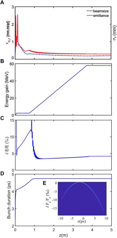
Figure 6. Photoinjector simulation results: (A) transverse emittance and beam size; (B) energy gain; (C) relative energy spread; (D) bunch duration; and (E) longitudinal phase space at exit of the photoinjector.
It is worth noting that even the final bunch length and energy spread are slightly larger than those of the conventional S-band photoinjector, and the longitudinal phase space clearly shows a second-order energy chirp. In this sense, this second-order energy chirp can be easily removed by a high-harmonic cavity [25], corrugated structures [26–28], or plasma linearizers [29, 30] without the need for a complex higher-order energy chirp compensation scheme.
4.3 High-repetition rate accelerator operation considerations
Since SLAC-type accelerators have been applied in irradiation accelerators for a long time, high-duty factor and high-power RF sources become the restrictions for high-repetition rate accelerator operations. A typical tens of MW high-power S-band klystron works on a short pulse (2–4 μs) and a low repetition rate up to 100 Hz. One-order duty factor improvement of these high-power RF source faces enormous challenges. On the other side, mature irradiation klystrons can provide a duty factor of near 1%, but their peak power is only 5 MW.
For a 3-m-long SLAC-type traveling-wave accelerator, the maximum energy gain without beam loading can be expressed as follows [31]:
5 Summary and outlook
In this paper, we have proposed a kHz high-repetition rate and-low emittance S-band photoinjector. By shortening the initial cell length to 0.4 cell and lowering the gun gradient to 60 MV/m at the same time, systematic dynamics simulations have shown that high-quality electron beams with 0.29 mm.mrad emittance and a 200 pC bunch charge can be generated using this novel photoinjector. Since this RF gun only needs 2.5 MW peak power with 1–2 μs pulse width, it can easily achieve the goal of kHz operation with a mature 5 MW S-band irradiation klystron, which can work on a high-duty factor of 1%. In addition, kHz high-repetition-rate operations of the main accelerator were also carefully considered. By adding a SLED pulse compressor, the main accelerators will work on a favorable gradient and kHz high-repetition rate using the same klystron as the RF gun.
In summary, in the physical aspect, our proposed injector can access equivalently bright electron beams as the existing low-duty factor S-band photoinjector, while the repetition rate or duty factor will get a tenfold improvement. In addition, low-gradient operation of the RF gun will bring benefits of better vacuum performance and lower dark current [33], which is very helpful for its compatibility with semi-conductor photocathodes. In the technical aspect, this low-gradient 1.4-cell RF gun can significantly reduce the difficulty of the manufacturing process and make it more accessible. Finally, we emphasize that this idea could be directly applied in the MeV UED community, where even a lower gun gradient (down to 30 MV/m) can work well, achieving a higher repetition rate in tens of kHz range that is within reach using mature pulsed power technologies.
Data availability statement
The original contributions presented in the study are included in the article/Supplementary Material; further inquiries can be directed to the corresponding authors.
Author contributions
TH: Formal Analysis, Data curation, Validation, writing–review and editing. LS: Software, Investigation, Supervision, writing–review and editing. HW: Investigation, writing–review and editing. DX: Formal Analysis, writing–review and editing. KZ: Methodology, writing–review and editing. PL: Conceptualization, Resources, writing–review and editing. JW: Visualization, writing–review and editing. HX: Data curation, Resources, writing–original draft. ZZ: Methodology, Supervision, Project administration, writing–original draft. ML: Supervision, writing–review and editing. DW: Supervision, writing–review and editing.
Funding
The author(s) declare that financial support was received for the research, authorship, and/or publication of this article. This work is supported by the National Natural Science Foundation of China (NSFC grant nos 12005211, 12305155, and 12375322).
Conflict of interest
The authors declare that the research was conducted in the absence of any commercial or financial relationships that could be construed as a potential conflict of interest.
Publisher’s note
All claims expressed in this article are solely those of the authors and do not necessarily represent those of their affiliated organizations, or those of the publisher, the editors, and the reviewers. Any product that may be evaluated in this article, or claim that may be made by its manufacturer, is not guaranteed or endorsed by the publisher.
References
1. Rao TS, Dowell DH. An engineering guide to photoinjectors (2013). Available at: https://arxiv.org/abs/1403.7539.
2. Xiao L, Boyce R, Dowell D, Li Z, Limborg-Deprey C, Schmerge J. Dual feed rf gun design for the lcls. In: Proceedings of the 2005 Particle Accelerator Conference (IEEE); 16 - 20 May 2005; Knoxville, TN, USA (2005). p. 3432–4.
3. Rosenzweig J, Cook A, Dunning M, Frigola P, Travish G, Sanelli C, et al. Rf and magnetic measurements on the sparc photoinjector and solenoid at ucla. In: Proceedings of the 2005 Particle Accelerator Conference (IEEE); 16 - 20 May 2005; Knoxville, TN, USA (2005). p. 2624–6.
4. Schietinger T, Pedrozzi M, Aiba M, Arsov V, Bettoni S, Beutner B, et al. Commissioning experience and beam physics measurements at the swissfel injector test facility. Phys Rev Acc Beams (2016) 19:100702. doi:10.1103/physrevaccelbeams.19.100702
5. Hong J, Han J, Park S, Kang H, Gil K, Chae M, et al. New rf-gun design for the pal-xfel. In: Proceedings of the FEL2012; 26-31 August 2012; Nara, Japan (2012). p. 26–31.
6. Zheng L, Du Y, Zhang Z, Qian H, Yan L, Shi J, et al. Development of s-band photocathode rf guns at tsinghua university. Nucl Instr Methods Phys Res Section A: Acc Spectrometers, Detectors Associated Equipment (2016) 834:98–107. doi:10.1016/j.nima.2016.07.015
7. Palmer D, Miller R, Winick H, Wang X, Batchelor K, Woodle M, et al. Simulations of the bnl/slac/ucla 1.6 cell emittance compensated photocathode rf gun low energy beam line. Proc Part Accelerator Conf (1995) 4:2432–4. doi:10.1109/PAC.1995.505574
8. Carlsten B. New photoelectric injector design for the los alamos national laboratory xuv fel accelerator. Nucl Instr Methods Phys Res Section A: Acc Spectrometers, Detectors Associated Equipment (1989) 285:313–9. doi:10.1016/0168-9002(89)90472-5
9. Akre R, Dowell D, Emma P, Frisch J, Gilevich S, Hays G, et al. Commissioning the linac coherent light source injector. Phys Rev ST Accel Beams (2008) 11:030703. doi:10.1103/PhysRevSTAB.11.030703
10. Qian H. Review of high brightness photoinjectors. In: Proc. IPAC’21 (JACoW Publishing, Geneva, Switzerland) no. 12 in International Particle Accelerator Conference; 24-28 May 2021; Campinas, SP, Brazil (2021).
11. Militsyn B, Cowie L, Goudket P, Jones T, McKenzie J, Wheelhouse A, et al. Design of the high repetition rate photocathode gun for the clara project. Proc Linac’ (2014) 14:1155–8.
12. Sannibale F. High-brightness electron injectors for high-duty cycle x-ray free electron lasers. Front Phys (2023) 11. doi:10.3389/fphy.2023.1187346
13. Zhou F, Adolphsen C, Dowell D, Xiang R. Overview of cw electron guns and lcls-ii rf gun performance. Front Phys (2023) 11. doi:10.3389/fphy.2023.1150809
14. Giribono A, Alesini D, Cardelli F, Di Raddo G, Faillace L, Ferrario M, et al. Dynamics studies of high brightness electron beams in a normal conducting, high repetition rate c-band injector. Phys Rev Accel Beams (2023) 26:083402. doi:10.1103/PhysRevAccelBeams.26.083402
15. Rosenzweig J, Cahill A, Dolgashev V, Emma C, Fukasawa A, Li R, et al. Next generation high brightness electron beams from ultrahigh field cryogenic rf photocathode sources. Phys Rev Acc Beams (2019) 22:023403. doi:10.1103/physrevaccelbeams.22.023403
16. Bazarov IV, Dunham BM, Sinclair CK. Maximum achievable beam brightness from photoinjectors. Phys Rev Lett (2009) 102:104801. doi:10.1103/PhysRevLett.102.104801
17. Pirez E, Musumeci P, Maxson J, Alesini D. S-band 1.4 cell photoinjector design for high brightness beam generation. Nucl Instr Methods Phys Res Section A: Acc Spectrometers, Detectors Associated Equipment (2017) 865:109–13. doi:10.1016/j.nima.2016.08.063
18. Song Y, Yang J, Tsai C, Fan K. Improvement of 6d brightness by a 1.4-cell photocathode rf gun for mev ultrafast electron diffraction. J Phys Conf Ser (2019) 1350:012048. doi:10.1088/1742-6596/1350/1/012048
19. Dwersteg B, Flöttmann K, Sekutowicz J, Stolzenburg C. Rf gun design for the tesla vuv free electron laser. Nucl Instr Methods Phys Res Section A: Acc Spectrometers, Detectors Associated Equipment (1997) 393:93–5. doi:10.1016/s0168-9002(97)00434-8
20. Xu H, Shi J, Du Y, Li R, Xing Q, Chen H, et al. Development of an l-band photocathode rf gun at tsinghua university. Nucl Instr Methods Phys Res Section A: Acc Spectrometers, Detectors Associated Equipment (2021) 985:164675. doi:10.1016/j.nima.2020.164675
22. Chen H, Zheng LM, Gao B, Li ZZ, Du YC, Li RK, et al. Beam dynamics optimization of very-high-frequency gun photoinjector. Nucl Sci Tech (2022) 33:116. doi:10.1007/s41365-022-01105-y
23. Prat E, Aiba M, Bettoni S, Beutner B, Reiche S, Schietinger T. Emittance measurements and minimization at the swissfel injector test facility. Phys Rev Spec Topics-Accelerators Beams (2014) 17:104401. doi:10.1103/physrevstab.17.104401
24. Chen H, Yan L, Tian Q, Lin Z, Wang D, Cheng C, et al. Commissioning the photoinjector of a gamma-ray light source. Phys Rev Acc Beams (2019) 22:053403. doi:10.1103/physrevaccelbeams.22.053403
25. Emma P. X-band rf harmonic compensation for linear bunch compression in the lcls. Slac, Stanford, Ca, Usa, Rep Ilcls-tn-01-1 (2001).
26. Craievich P. Passive longitudinal phase space linearizer. Phys Rev Spec Topics-Accelerators Beams (2010) 13:034401. doi:10.1103/physrevstab.13.034401
27. Deng H, Zhang M, Feng C, Zhang T, Wang X, Lan T, et al. Experimental demonstration of longitudinal beam phase-space linearizer in a free-electron laser facility by corrugated structures. Phys Rev Lett (2014) 113:254802. doi:10.1103/physrevlett.113.254802
28. Fu F, Wang R, Zhu P, Zhao L, Jiang T, Lu C, et al. Demonstration of nonlinear-energy-spread compensation in relativistic electron bunches with corrugated structures. Phys Rev Lett (2015) 114:114801. doi:10.1103/physrevlett.114.114801
29. Wu Y, Hua J, Zhou Z, Zhang J, Liu S, Peng B, et al. Tunable plasma linearizer for compensation of nonlinear energy chirp. Phys Rev Appl (2021) 16:024056. doi:10.1103/physrevapplied.16.024056
30. Wu Y, Zhou Z, Du Y, Hua J, Lu W, Mori WB, et al. Linearization of an electron beam’s longitudinal phase space using a hollow-channel plasma. Phys Rev Appl (2023) 19:064013. doi:10.1103/physrevapplied.19.064013
32. Farkas Z, Hogg H, Loew G, Wilson PB. Sled: a method of doubling slac’s energy. In: Proc. Of 9th Int. Conf. On High Energy Accelerators, SLAC; May 2-7, 1974; Stanford, California (1974). p. 576.
33. Chen H, Du Y, Gai W, Grudiev A, Hua J, Huang W, et al. Photocathode emission studies: dark current and Schottky-enabled photo-electrons in a high-field rf gun. In: AIP Conference Proceedings (American Institute of Physics) vol. 1507; 1-12 October 2012; Vietri sul Mare, Salerno, Italy (2012). p. 435–9.
Keywords: photoinjector, RF gun, LINAC, electron beam, repetition rate, emittance
Citation: He T, Shan L, Wang H, Xiao D, Zhou K, Li P, Wang J, Xu H, Zhou Z, Li M and Wu D (2024) Design of a kilohertz repetition rate, low-emittance S-band photoinjector. Front. Phys. 12:1361909. doi: 10.3389/fphy.2024.1361909
Received: 27 December 2023; Accepted: 18 March 2024;
Published: 09 April 2024.
Edited by:
Javier Resta López, University of Valencia, SpainReviewed by:
Calin Ioan Hojbota, Institute for Basic Science (IBS), Republic of KoreaVitaliy Goryashko, Uppsala University, Sweden
Copyright © 2024 He, Shan, Wang, Xiao, Zhou, Li, Wang, Xu, Zhou, Li and Wu. This is an open-access article distributed under the terms of the Creative Commons Attribution License (CC BY). The use, distribution or reproduction in other forums is permitted, provided the original author(s) and the copyright owner(s) are credited and that the original publication in this journal is cited, in accordance with accepted academic practice. No use, distribution or reproduction is permitted which does not comply with these terms.
*Correspondence: Zheng Zhou, z-zhou14@tsinghua.org.cn; Hanxun Xu, xhx16@tsinghua.org.cn