Study of mechanical behavior of grout sleeve splicing of rebars
 Yuzhe Sun
- School of Civil Engineering, Xi’an University of Architecture and Technology, Xi’an, Shaanxi, China
In order to analyze the influence of grout strength, rebar diameter, sleeve material and anchorage length on performance of grout sleeve splicing of rebars, 72 specimens were designed and fabricated. The experimental results revealed that the failure modes included three forms, namely rebar fracture, sleeve rupture and bond slip between the rebar and grout. The tensile strength increased with the increase of grout strength and anchorage length of rebar at the same time, demonstrating that the sleeve could effectively transfer the bond stress. The sleeve strain gradually increased from the mechanical connection end to the grout connection end, illustrating linear pattern. Based on the failure mechanism of the grout sleeve splicing of rebars and the experimental results, the calculation formula of the anchorage length of grout sleeve splicing of rebars was proposed considering the grout strength and sleeve inner diameter.
1 Introduction
The mechanical performance of connections between precast components directly affects the property of the precast concrete structure. The connection performance is primarily influenced by the rebar and concrete at the connection joint. To enhance the bonding performance between new and existing concrete, the treatment of the concrete interface typically involves shear keys, roughened surfaces and other methods. For the connection of reinforcements, primary methods include grouted sleeve connections, bonded anchor lap connections, and extruded sleeve connections.
The technique of grout sleeve splicing of rebars first introduced by Dr. Yee [1] in 1970, setting the foundation for subsequent comprehensive research for precast wall panels. Wu [2] conducted pull-out tests on 12 steel sleeves elucidating the failure process of grouted sleeves, which comprises four distinct stages: elasticity, yielding, hardening, and necking, then proposed a calculation model for longitudinal and transverse stress of the sleeve shell under axial tension. Similarly, Zheng et al [3] proposed a novel sleeve design utilizing low-alloy seamless steel tubes. Through finite element analysis of interactions among the sleeve, grout, and rebar, a design methodology for deformable sleeves was developed to satisfy the strength and deformation criteria prescribed for Grade I joints by industry standards. Henin [4] introduced a cost-effective connection sleeve tailored to rebar diameter, grout strength, and design tolerances, emphasizing simplicity in production. Subsequent research by Ling [5] assessed the performance of cylindrical and conical sleeve connections for rebars. Key findings revealed an inverse relationship between bond strength and sleeve diameter, while the anchorage length of the rebar directly impacted bond strength. Specifically, the conical sleeve exhibited superior performance in constraining the expansion of circumferential cracks compared to the cylindrical sleeve. Yin [6] designed the experiment to study the dynamic characteristics of full-grouted sleeve connection, showing that the bearing capacity and maximum strain were higher than that of the static one. Moreover, the seismic behavior of precast component connected using grouting sleeve connections analyzed by experimental and numerical investigation, including hysteretic behaviour, stiffness degradation and energy-dissipation capacity [7].
To reduce the economic cost of grouted sleeve connections of rebars, the restraint grouting-anchoring overlap-joint of steel bar proposed. This method offers advantages such as simplicity, ease of construction, and low cost. Jiang [8] considered main influencing parameters such as rebar diameter, concrete strength, and anchorage length, and conducted pull-out studies on 81 specimens, demonstrating the reliability of the connection. It is suggested that the anchorage length can reduce to 0.8 times of basic anchorage length. Ma [9] took into account the diameter of longitudinal rebar, the length of longitudinal rebar lap, the volume ratio of stirrups, and concrete strength, and investigated the mechanical performance of 144 specimens restraint grouting-anchoring overlap-joint of steel bar. The bond-slip failure would not occur as the lap length is greater than the basic anchorage length. Wu [10] proposed a welded reserved-hole rebar grout-anchor lap connection technique, considering rebar diameter, lap length, and cross-sectional size, which has a high load-bearing capacity and a short lap length. Qiong Yu [11] proposed a sleeve-constrained grout-anchor lap connection, considering rebar diameter and lap length. The load-displacement curves and ultimate bearing capacity were close to the material properties of the steel.
The longitudinal rebar connections in precast components primarily include grouted sleeve connections and restraint grouting-anchoring overlap-joint, which have demonstrated can effectively achieve rebar connections in precast structures. However, the calculation formulas for the anchorage length of grouted sleeve connections have not yet provided. This paper focuses on the grout sleeve splicing of rebars and conducts pull-out experiment. It analyzes the effects of grout strength, anchorage length, sleeve material, and rebar diameter on the connection performance, and proposes a calculation formula for the anchorage length of grouted sleeve connections.
2 Materials and methods
2.1 Specimen fabrication
This experimental study focused on the performance of half grouted sleeve connections of rebars, which one end of the grout sleeve was mechanical connection, and the other end was grouting sleeve connection. Initially, the varying diameters with different anchorage lengths was processed, such as diameters of 18 mm, 24 mm, and 30 mm for C12, C16, and C20, respectively. Subsequently, the same rebar was screwed into the mechanical connection of the sleeve using a wrench. Finally, the sleeve, yet to be grouted, was secured in place, followed by the execution of sleeve grouting operations using a manual grouting gun.
2.2 Specimen testing and loading
2.2.1 Strain gauge arrangement
Four strain gauges were uniformly arranged along the axial direction on the outer shell of the sleeve, numbered sequentially from the mechanical connection to the grouting connection as strain gauges 1, 2, 3, and 4. To avoid the adverse effects of rebar polishing on the sleeve grouting connection, the rebar strain gauges were placed 25 mm away from the outside of both the mechanical and grouting connection ends.
2.2.2 Loading regime of specimens
The experiment was conducted in the Key Laboratory of Structural Engineering and Earthquake Resistance. The instrument used was a WAW-1000WE type micro-control electro-hydraulic servo universal testing machine. The TDS-530 data acquisition instrument was used to collect steel rebar and sleeve strain.
According to the “Technical Specification for Mechanical Connections of Steel Reinforcing Bars” (JGJ 107-2010) [12], the loading regime for the specimens is as follows: 0→0.6 fyk→0 (measurement of residual deformation)→maximum tensile stress (recording tensile strength)→0 (determination of total elongation).
3 Results
During the test, mechanical properties such as yielding strength, ultimate strength, and total elongation of the grout sleeve splicing of rebars were recorded. The experimental results are presented in Tables 1, 2, respectively. The load-displacement curves, strains of steel rebar and sleeve, and the final failure modes of the specimens analyzed. The final failure modes of the grouted sleeve connection specimens were classified into three types:
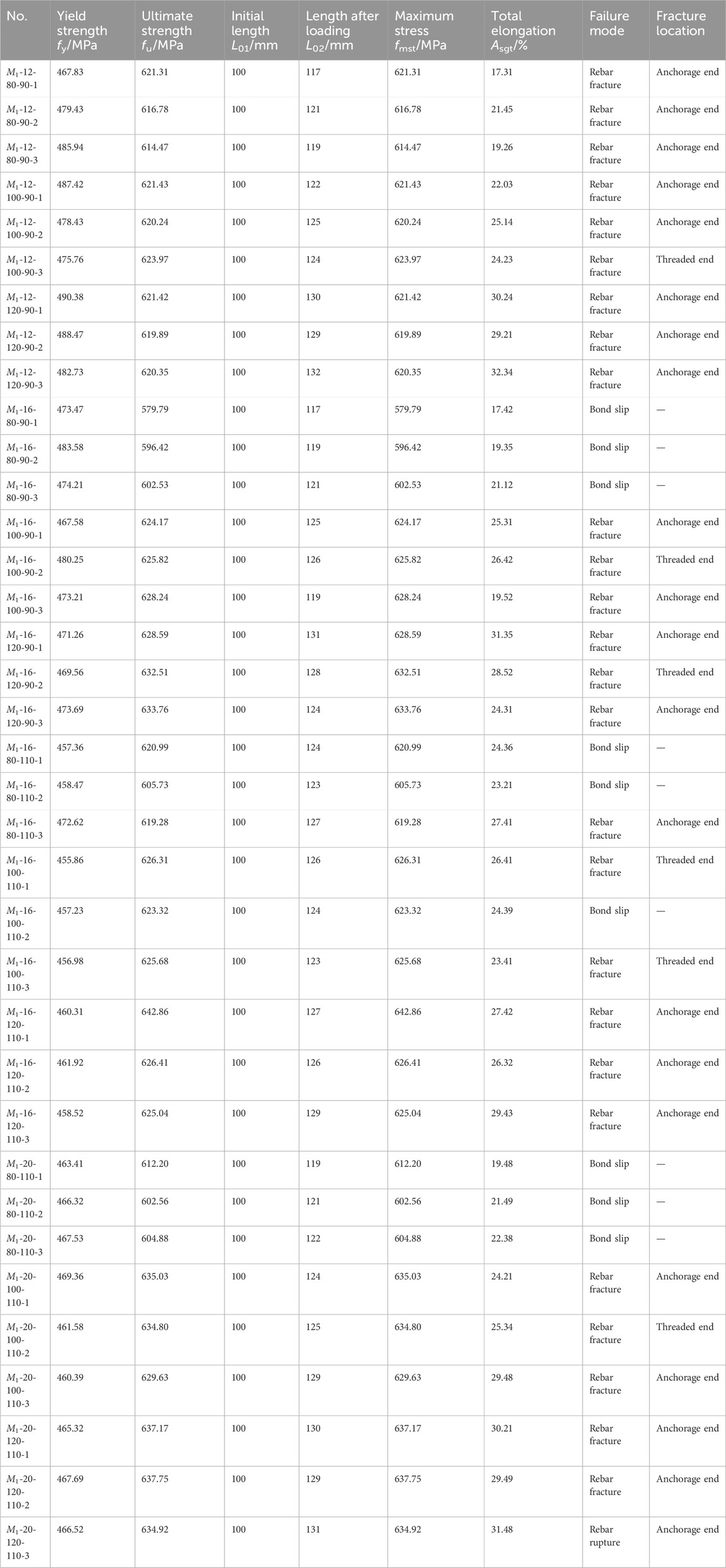
Table 1. Test results of steel grouted sleeve connection specimens.
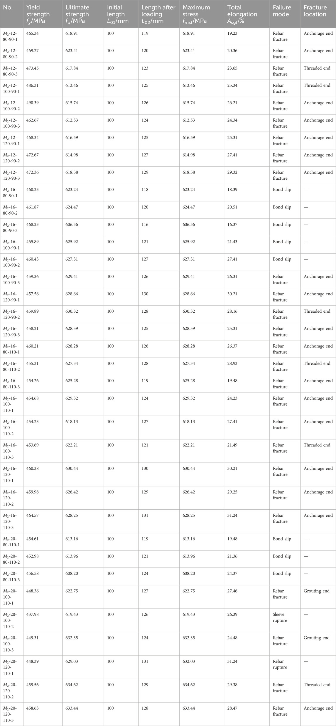
Table 2. Test results of cast iron grouted sleeve connection specimens.
3.1 Rebar fracture
The rebar fractured outside the sleeve, representing the ideal failure mode and the primary failure type observed in the experiments. It indicated that the tensile strength of the grouted sleeve connection was not less than that of the rebar, reflecting that the rebar anchorage length was suitable, and the strength of the grouting material and the performance of the sleeve met the ideal performance requirements.
3.2 Bond-slip failure
The main instances of bond-slip failure were observed in the M1-16-80-90, M2-16-80-90, M2-16-100-90, M1-16-80-110, M1-20-80-110, and M2-20-80-110 groups, where the specimens primarily had a grouting strength of 80 MPa and larger rebar diameters with insufficient anchorage length, indicating that the strength of the grouting and the anchorage length were the main reasons for bond-slip failure. Specimens with bond-slip failure exhibited virtually no rebar strengthening phase and lacked ductile deformation capability.
3.3 Sleeve fracture
In the experiments, only the specimen M2-20-100-110-2 experienced sleeve fracture, primarily due to the low tensile strength of the cast iron sleeve itself. It is necessary to improve the production quality of the sleeve.
4 Discussion
4.1 Sleeve strain analysis
In the pull-out tests of the half-grouted sleeve connection, the axial load was transmitted from the rebar at the grouting end to the grout, then from the grout to the sleeve shell, and subsequently from the sleeve shell to the mechanical connection, where it was finally transferred to the rebar through the threads. The analysis of the strain on the outer shell of the sleeve indicated that the strain on the sleeve shell increased gradually from the mechanical connection end to the grout connection end. This suggested that the deformation of the grout was greatest at the grouting end, where the stress was also highest, and least at the mechanical connection end, where the stress was lower. The change in strain along the sleeve shell typically follows a linear pattern, as illustrated in Figure 1.
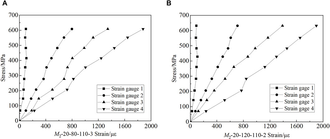
Figure 1. Strain in the sleeve shell. (A) M2-20-80-110-3 (B) M2-20-120-110-2.
4.2 Analysis of tensile strength
4.2.1 Grout strength
The strength of the grouting material has a minimal impact on the yield strength of half-grouted sleeve grouted connection specimens, and there was considerable variability in the yield strength of specimens that experienced bond-slip failure. The yield strength of steel grouted sleeve connections decreased slightly, with bond-slip failures primarily concentrated in specimens with a grouting strength of 80 MPa. The yield strength of cast iron grouted sleeve connections remained essentially unchanged, with bond-slip failures mainly occurring at a grouting strength level of 80 MPa (Figures 2A, B). As shown in Figures 2C, D, the ultimate strength of both steel and cast iron half-grouted sleeve connection specimens increased with the grade of grout strength, and the strength variability of steel sleeve specimens was less significant.
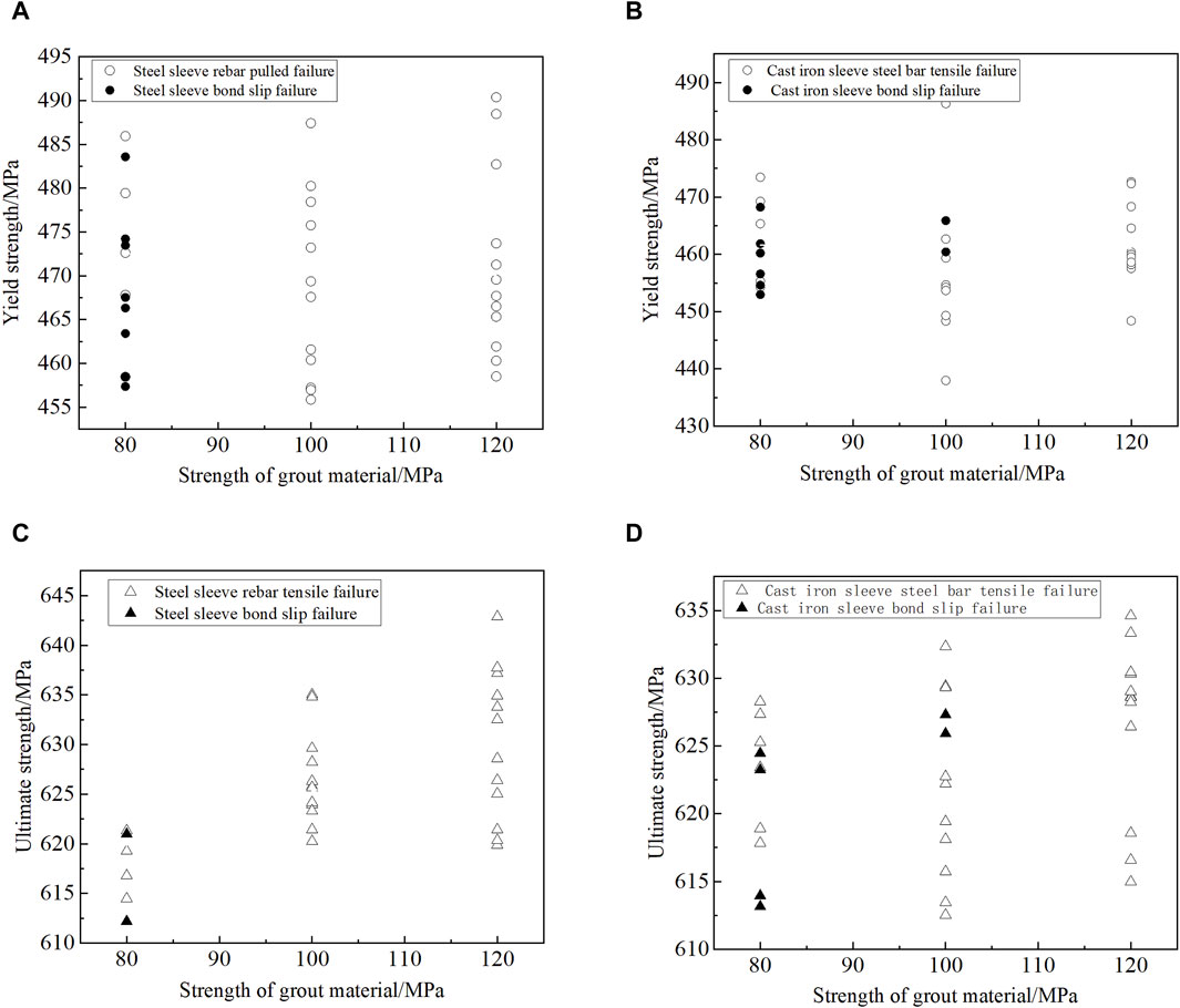
Figure 2. Influence of grout strength on the tensile strength of half-grouted sleeve specimens (A) Yield strength of steel sleeve specimens (B) Yield strength of cast iron sleeve specimens (C) Ultimate strength of steel sleeve specimens (D) Ultimate strength of cast iron sleeve specimens.
4.2.2 Anchorage length
The yielding strength and ultimate strength of half-grouted sleeve connection specimens were analyzed based on the ratio of rebar anchorage length to rebar diameter, as shown in Figure 3. For steel half-grouted sleeve specimens, specimens with rebar anchorage lengths of 5.5d, 5.6d, and 6.8d all exhibited bond-slip failures, while specimens with 7.5d did not show bond-slip failure and had higher yielding strength. Regarding the yielding strength of cast iron half-grouted sleeve specimens, specimens with rebar anchorage lengths of 5.5d and 5.6d experienced bond-slip failures, while those with 6.8d and 7.5d did not display higher yield strengths. Regarding the ultimate strength of both steel and cast iron half-grouted sleeve specimens, there was a slight decrease as the anchorage length increased. By examining the yield and ultimate strengths of specimens with bond-slip failure, it was found that these values were lower than those of specimens with ideal failure modes. The most significant difference was the lack of strengthening phase, resulting in reduced ductility.
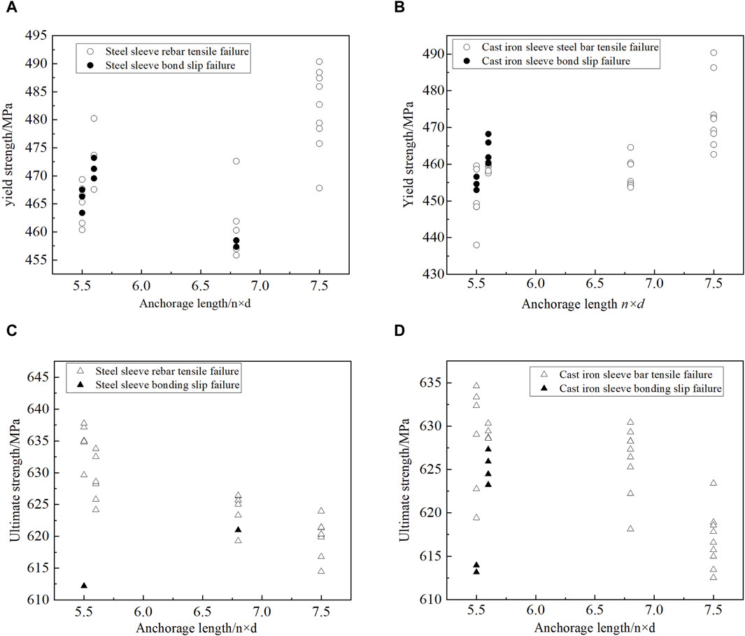
Figure 3. Effect of anchoring length on the tensile strength of half-grouted sleeve specimens (A) Yield strength of steel sleeve specimens (B) Yield strength of cast iron sleeve specimens (C) Ultimate strength of steel sleeve specimens (D) Ultimate strength of cast iron sleeve specimens.
4.3 Calculation of anchorage length
From the pull-out tests of half-grouted sleeve connection specimens of rebars, it was concluded that specimens with higher grouting strength and appropriate anchorage length exhibited failure modes of connected rebar fracture, and the ultimate tensile strength of these specimens exceeded 1.1 times the standard value of the ultimate tensile strength for HRB400 grade rebar, meeting the technical requirements of the “Technical Specification for Grouted Sleeve Connections of Reinforcing Bars” (JGJ 355-2015) [13].
The most crucial parameter for the design of grouted sleeve connections is the length of anchorage of the rebar. Although JGJ 355-2015 uniformly specifies that the insertion depth of the connected rebar should not be less than 8 times the diameter of the rebar, it does not consider the impact of factors such as grouting strength and the inner diameter of the sleeve and the calculation formula is not yet clear.
Based on the force transfer mechanism between the rebar and the grout, the basic anchorage length formula for the rebar in the grouted sleeve is derived from the principle of force equilibrium that the resultant force of bond stress along the rebar equal to the external load.
In the formula, τ represents the average bond strength between the rebar and the grout; lab is the basic anchorage length of the rebar in the grout sleeve; d is the diameter of the connected rebar; F is the axial load corresponding to the standard value of the rebar yield strength.
The formula for calculating the rebar bond strength τ is as follows:
Where, μ is the friction coefficient between the rebar and the grout; q is the radial pressure exerted by the grout on the rebar. According to the description in the literature [4], the friction coefficient between the rebar and the grout can be taken as 1, i.e., τ = q.
Based on the stress relationship between the grout and the rebar and between the grout and the sleeve, as shown in Figure 4, the relationship between q and the sleeve stress Fs is established as follows:
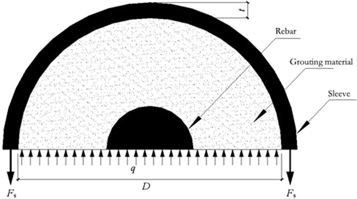
Figure 4. Internal force relationship in half-grouted sleeve connections of rebars.
Where, D is the inner diameter of the sleeve; t is the thickness of the sleeve shell; Fs is the yield strength of the sleeve.
From Eq. 3, q is determined as follows:
According to research in related literature, the maximum normal pressure generated by the grouting around the rebar does not exceed 0.2 times the
From Eqs 1–4, the theoretical anchorage lengths for grouted sleeve connection specimens with different rebar diameters, grout strengths, and inner sleeve shells can be calculated. According to the mechanical performance indicators of sleeve materials in “Grouted Sleeve for Rebar Connection” (JG/T 398-2012) [14], the yield strength of steel sleeves was 355 MPa, and the tensile strength of cast iron sleeves was 600 MPa, with their yield strength assumed the same as that of steel sleeves at 355 MPa. Finally, the basic anchorage length calculation formula for the grouted sleeve is:
According to the calculation results of Eq. 5, the calculated basic anchorage lengths for steel half-grouted sleeve connection of rebars and cast iron half-grouted sleeve connections were generally consistent with the experimental observations. For example, when the grout strength was 80 MPa, the theoretical calculated lengths for rebars of 16 mm and 20 mm diameter were 125 mm, whereas in the experiments they were 90 mm and 110 mm, respectively. Therefore, the experimental failure mode of these specimens is primarily bond-slip failure.
5 Conclusion
This study conducted pull-out tests on 72 grout sleeve splicing of rebars, concluding that grouted sleeve connection specimens with mechanical properties are equivalent to those of the connected reinforcing bars should possess adequate anchorage length and grout strength, demonstrating sufficient bond strength. The main conclusions include:
1. The failure mode of half-grouted sleeve connection specimens of reinforcements was primarily rebar fracture. Bond-slip failure mainly occurred due to insufficient grout strength and inadequate anchorage length; sleeve fracture was mainly due to defective products.
2. Based on the analysis of experimental results, the influence of grout strength and rebar anchorage length to rebar diameter on the yield strength and ultimate strength of the specimens were analyzed. The tensile strength of the specimens increased with the increase in grout strength and rebar anchorage length to rebar diameter.
3. Through the analysis of influencing factors, a theoretical formula for anchorage length was derived according to the load-transferring mechanism of grouted sleeve connections of rebars.
Data availability statement
The raw data supporting the conclusion of this article will be made available by the authors, without undue reservation.
Author contributions
YS: Writing–original draft, Writing–review and editing.
Funding
The author(s) declare that no financial support was received for the research, authorship, and/or publication of this article.
Conflict of interest
The author declares that the research was conducted in the absence of any commercial or financial relationships that could be construed as a potential conflict of interest.
Publisher’s note
All claims expressed in this article are solely those of the authors and do not necessarily represent those of their affiliated organizations, or those of the publisher, the editors and the reviewers. Any product that may be evaluated in this article, or claim that may be made by its manufacturer, is not guaranteed or endorsed by the publisher.
References
2. Wu T, Liu Q, Cheng R. Experimental study on the performance of steel sleeve grouting connection and stress analysis of the cylinder wall. Eng Mech (2017) 34(10):68–75. (in Chinese). doi:10.6052/j.issn.1000-4750.2016.05.0357
3. Zheng Y, Guo Z. Experimental research and finite element analysis on the performance of deformation grouting sleeve connection. J Building Structures (2016) 37(3):94–102. (in Chinese). doi:10.14006/j.jzjgxb.2016.03.012
4. Henin E, Morcous G. Non-proprietary bar splice sleeve for precast concrete construction. Eng Structures (2015) 83:154–62. doi:10.1016/j.engstruct.2014.10.045
5. Ling JH, Rahman ABA, Ibrahim IS, et al. Behaviour of grouted pipe splice under incremental tensile load. Construction Building Mater (2009) 23(3):90–8. doi:10.1016/j.conbuildmat.2012.02.001
6. Yin F, Yin S, Cheng Z, Wang Y. Experimental research on dynamic mechanical properties of fully-grouted sleeve connections. Construction Building Mater (2021) 288:123125. doi:10.1016/j.conbuildmat.2021.123125
7. Tong G, Jun Y, Liu T, et al. Experimental and numerical investigation of the seismic behaviour of corroded precast concrete piers with grouting sleeve connections. Struct Infrastructure Eng (2023):2209070. doi:10.1080/15732479.2023.2209070
8. Jiang H, Zhang H, Liu W. Anchorage performance of grouted steel bars in embedded reserved holes of prefabricated concrete structures. J Harbin Inst Technol (2011) 43(4):28–31. (in Chinese).
9. Ma J, Yin W, Liu S. Experimental study on reinforcement constrained grout anchor overlap connection. Building Struct (2015)(2) 32–5. doi:10.19701/j.jzjg.2015.02.008
10. Wu T, Liu Q, Zhao T. Experimental study on overlapping of reinforcement grout anchors with reserved holes in prefabricated prefabricated structures. Ind Construction (2017)(5) 68–73. doi:10.13204/j.gyjz201705014
11. Yu Q, Xu Z, Yuan W. Tensile test of sleeve constrained slurry anchor lap joint under two factors. J Harbin Inst Technol (2016) 48(12):34–42. (in Chinese). doi:10.11918/j.issn.0367-6234.2016.12.004
12. JGJ 107-2010. Technical specifications for mechanical connection of steel bars. Architecture & Building Press (2010).
13. JGJ 355-2015. China architecture and construction. Press (2015).Technical specification for application of reinforcement sleeve grouting connection
Keywords: grout sleeve splicing of rebars, failure mechanism, sleeve strain, anchorage length, mechanical model
Citation: Sun Y (2024) Study of mechanical behavior of grout sleeve splicing of rebars. Front. Phys. 12:1397218. doi: 10.3389/fphy.2024.1397218
Received: 07 March 2024; Accepted: 08 April 2024;
Published: 19 April 2024.
Edited by:
Riccardo Meucci, National Research Council (CNR), ItalyCopyright © 2024 Sun. This is an open-access article distributed under the terms of the Creative Commons Attribution License (CC BY). The use, distribution or reproduction in other forums is permitted, provided the original author(s) and the copyright owner(s) are credited and that the original publication in this journal is cited, in accordance with accepted academic practice. No use, distribution or reproduction is permitted which does not comply with these terms.
*Correspondence: Yuzhe Sun, 1269859583@qq.com