 Nasir Saeed
 Tareq Y. Al-Naffouri2
 Mohamed-Slim Alouini
- 1Department of Electrical Engineering, National University of Technology (NUTECH), Islamabad, Pakistan
- 2Computer Electrical and Mathematical Sciences and Engineering (CEMSE) Division, King Abdullah University of Science and Technology (KAUST), Thuwal, Saudi Arabia
Current ground-based transportation systems are subjected to various challenges, including the high cost of infrastructure development, limited land space, and a growing urban population. Therefore, the automotive and aviation industries are collaborating to develop flying cars, also known as electric, vertical, takeoff, and landing aircrafts (eVTOLs). These eVTOLs will allow for rapid and reliable urban and suburban transportation. Safe operation of eVTOLs will require well-developed wireless communication networks; however, existing communication technologies need enhancement in order to provide services to flying cars. We describe several potential innovations that make communication between eVTOLs and the ground feasible. These innovations include three-dimensional cellular networks on-ground, tethered balloons, high-altitude platforms, and satellites.
1 Introduction
Flying promises a boundless freedom that has always been a dream of human society. To fulfill this dream, the aviation and automobile industries have pushed the bounds of innovation to introduce electric, vertical, takeoff, and landing vehicles (eVTOLs). Compared to infrastructure-heavy ground-based transportation systems such as roads, bridges, rail tracks, and tunnels, networks of eVTOLs will likely have low costs Ullman et al. (2017); Balac et al. (2019); Choi and Hampton (2020). In the near future, these eVTOLs will enhance “on-demand” mobility for intra- and intercity transportation, improving connectivity between metropolitan city centers and airports Moore et al. (2013). Because of this growing interest in eVTOL development, over a dozen companies have been working passionately to bring the dream of eVTOLs to reality. Some of the ongoing eVTOL projects include Uber Air VTOL Taxi Uber (2020a), Airbus Vahana Airbus (2020), Kitty Hawk Cora Hawk (2020), Toyota SkyDrive Toyota (2020), Terrafugia Terrafugia (2020), and AeroMobil Aeromobil (2020) (Figure 1). At the moment, eVTOL technology faces a number of challenges, including the need for certification from the regulation authorities, a dearth of efficient batteries for long-range transportation, interference with the existing air traffic control systems, the need for developing the communication system, few safety considerations, high vehicle noise, and the need for the vertical ports Rajashekara et al. (2016); Sutherland (2019); Pan and Alouini (2021). All these are open research questions. Few studies have focused on the sustainability, power, and energy requirement of eVTOLs Kasliwal et al. (2019), and the existing works have failed to delineate the role of wireless communication technologies in eVTOLs. Notwithstanding this lack of research, AT&T and Uber have convened a joint venture to provide 4G and 5G connectivity to their eVTOLs Uber (2020b). This project is still in its earliest stages, but may become a 5G use case in the near future. Moreover, the evolving wireless communication networks toward sixth generation (6G) envision to serve the eVTOLs by 2030 Dang et al. (2020); Giordani et al. (2020). Concentrating on the importance of wireless networks for eVTOLs, we report on various possible connectivity solutions that provide both safety and autonomous operation.
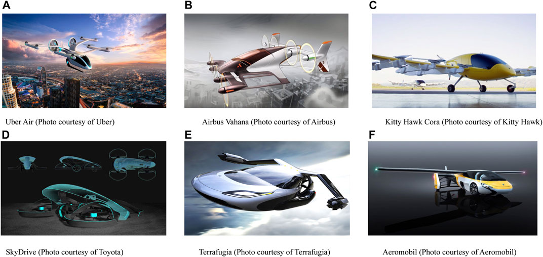
FIGURE 1. Some ongoing projects using eVTOL technology for urban air mobility.
To address the issue of communication in flying cars, we need to briefly look at the technologies used by the on-ground intelligent transportation systems (ITSs). For instance, dedicated short-range communication (DSRC), which operates at 5.9 GHz, has been adopted for vehicular network safety applications in many parts of the world Zhou et al. (2020). Although DSRC is a well-established technology, it is short-range, has a low data rate and high latency, and suffers from interference in dense urban environments. Due to its low reliability and considerable delay, DSRC cannot support autonomous driving Wang et al. (2019). However, cellular technologies such as long-term evolution-vehicle (LTE-V), which are dedicated to vehicular communications, have long transmission ranges, low latency, and higher data rates Ahmad et al. (2019), making them much more supportive of autonomous driving. LTE-V is a fourth-generation (4G) technology that can support high-speed autonomous driving. LTE-V operates in two modes: 1) direct vehicle-to-vehicle communication that does not involve the cellular infrastructure, and 2) vehicle-to-infrastructure communication, in which vehicles route their data through the cellular network. Among the six levels of autonomy defined by the Society of Automotive Engineers (SAE) from 0 (full control with the driver) to 5 (fully autonomous), the existing LTE-V system can support level 2 (partial automation) Chen et al. (2020). However, the fundamental properties of 5G technology, such as high capacity, flexibility, extremely low latency, and shorter wavelengths, can pave the way for fully autonomous and connected vehicles Nizzi et al. (2019). Also, 5G technology, along with software-defined networking and network virtualization, can make 5G technology remarkably favorable for autonomous cars Yaqoob et al. (2020).
All of these communications technologies for ground-based connected vehicles may fail or require significant modifications to enable connectivity for flying cars, since these technologies have insufficient aerial coverage. The eVTOL cruising altitude is around 300 meters, requiring new airborne networks or modifications for existing terrestrial cellular networks in order to supply communication, safety, and reliability to eVTOLs and prompting us to investigate novel technologies to provide aerial connectivity for eVTOLs. Hence, we describe various possible solutions that can enable connectivity in eVTOL networks. We design the link between the eVTOL and the base station (BS), where the BS can be either on the ground or airborne (Figure 2). On the ground, we employ cellular BSs, whereas airborne BSs can be tethered balloons (TBs), high-altitude platforms (HAPs), or satellites. As a part of our analysis, we consider achievable capacity, signal-to-noise ratio, and received power as key performance indicators. We first design the link between the eVTOL and a three-dimensional cellular BS in terms of the received power at the eVTOL. Then we discuss the link between a TB and eVTOL for varying distances up to a maximum of 20 kilometers. Next, we analyze the communication link between a HAP and eVTOL in terms of the achievable capacity at various frequencies. Finally, we design the link between the satellites and the eVTOL in terms of the operating frequency and altitude of the satellites. Further details are available in Methods and Results sections.
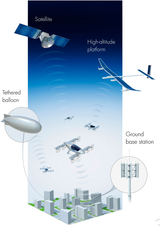
FIGURE 2. Potential eVTOL connectivity solutions.
2 Material And Methods
This section outlines various wireless communication solutions for flying cars. We consider achievable capacity, signal-to-noise ratio, and received power as key performance indicators for various link designs.
2.1 Cellular BS-to-eVTOL Link Design
Consider a terrestrial cellular network BS with additional antennas pointing toward the sky for aerial coverage, as shown in Figure 2. Let
where r is the eVTOL-to-BS projection distance on the ground and
where
where
where
2.2 TB-to-eVTOL Link Design
The communication link between TBs and eVTOLs can be modeled by taking into account large-scale and small-scale fading. Large-scale fading mainly occurs because of free space path loss (FSPL) and atmospheric attenuation. As such,
where c is the speed of light, d is the distance between the TB and the eVTOL, and f is the operating frequency. Since the TB-to-eVTOL link consists of a predominant line-of-sight (LoS) path, the multipath effect can be modeled by using the Rician distribution. The fading amplitude r at time instant i is expressed as
where
In the best-case scenario with a clear predominant LoS path,
where
where v is the speed of the eVTOL. If the eVTOL is directly moving toward the TB, then the resulting Doppler shift is positive; however, when the eVTOL is moving away from the TBs, the Doppler shift is negative. Based on these relevant effects, the channel model described by the received power at the eVTOL from the TB is expressed as follows (Khuwaja et al. (2018)):
where
where B is the available bandwidth and
2.3 HAP-to-eVTOL Link Design
Figure 2 shows the architecture for a network of HAPs in the stratosphere, providing connectivity to the eVTOL. Consider that the HAP is at altitude A having coverage with radius R at the eVTOL’s height. Then for the eVTOL at any point P in R, the elevation angle to the HAP is defined as
where
The path loss by the eVTOL at point P as a function of θ and frequency is given as (ITU (2019)):
The atmospheric loss for the HAP-to-eVTOL link at point A is given as
where
where
2.4 Satellite-to-eVTOL Link Design
The energy-per-bit to noise spectral density for a satellite-to-eVTOL link mainly depends on the link budget, which can be expressed as (Saeed et al. (2020)):
where
• The free space path loss,
• The atmospheric loss,
• The polarization loss,
• The antenna misalignment loss,
Based on these losses, the total loss
In addition to these losses, the elevation angle between the satellite and the eVTOL is also an important factor. When the satellite is above the eVTOL, that is, the satellite elevation angle is 90°, then the path loss is minimal, whereas above or below 90° can lead to a higher path loss. This is mainly due to the increased path length between the satellite and the eVTOL.
3 Results
The stages of an eVTOL’s flight consist of takeoff, hover, climbing, cruising, descending, and landing. Each type of the eVTOL has a different flight profile with a distinct cruising and takeoff/landing style. The typical flight profile of an eVTOL is shown in Figure 3. During takeoff, climbing, descending, and landing, eVTOLs can communicate using conventional on-ground networks. However, a significant part of the eVTOL flight profile consists of a cruising phase in which on-ground communication networks fail. Therefore, our primary results consider the potential solutions for designing the communication link in the cruising stage. Note that the key input parameters for the results are given in Table 1.
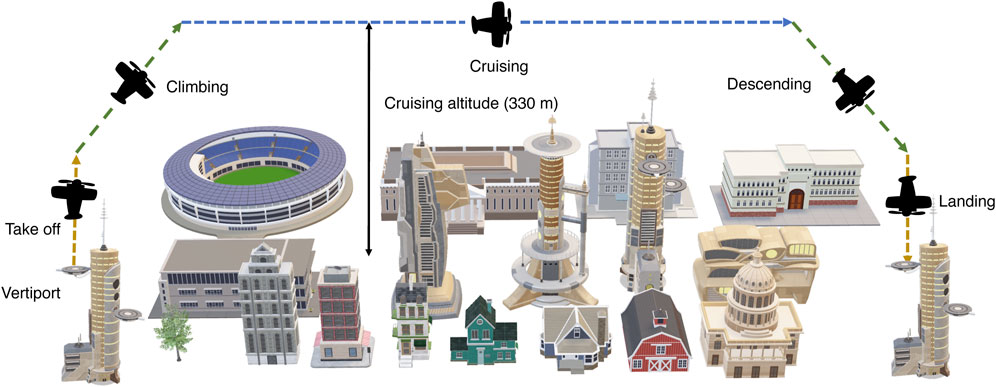
FIGURE 3. Flight plan of an eVTOL in a metropolitan area.
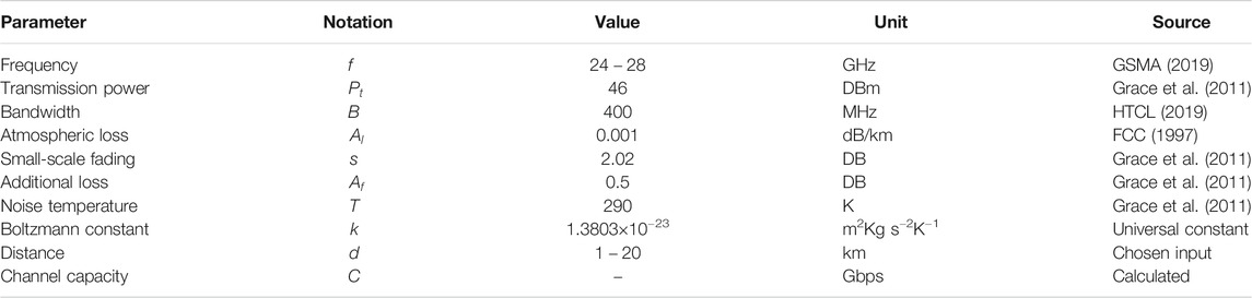
TABLE 1. Channel model parameters.
3.1 Connectivity Using Cellular Networks
One technology that can potentially enable eVTOL connectivity is ground-based cellular networks. Since on-ground BSs are stationed at a lower elevation than the cruising altitude of the eVTOLs, the BS-to-eVTOL link will consist of both line-of-sight (LoS) and non–line-of-sight (NLoS) components. The NLoS component arises due to obstacles such as high-rise buildings; therefore, we must calculate the received power for both the LoS and NLoS components of a BS-to-eVTOL link. To illustrate, consider an eVTOL flying at a cruising altitude (330 m) and communicating with the modified ground BS that has three-dimensional coverage, enabling aerial connectivity. We analyze the eVTOL at three different projection distances from the BS, that is , 0.5, 1, and 1.5 km, respectively. Figure 4 shows that as the projection distance between the eVTOL and BS increases (the black and blue colors represent the highest and lowest projection distances, respectively), the received power decreases due to the inverse relationship between the path length and the received power. Furthermore, Figure 4 plots the received power at the eVTOL for both LoS and NLoS paths at different frequencies. It is clear from Figure 4 that the environmental obstacles reduce the received power, for instance, at 20 GHz of frequency and 1 km path length, the received power for LoS component is −97 dBs, whereas for the NLoS component it is significantly lower −200 dBs. Moreover, Figure 4 demonstrates that the path loss increases at higher operating frequencies due to greater attenuation.
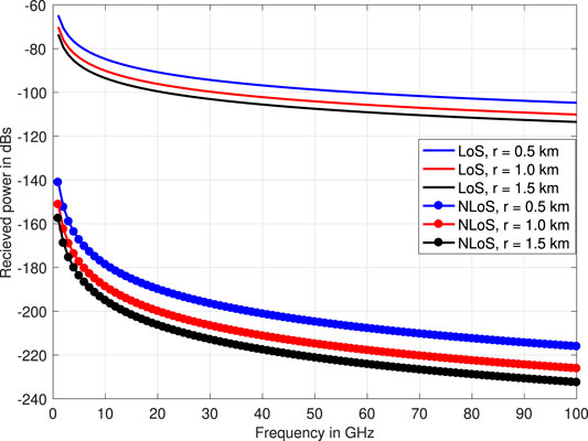
FIGURE 4. Received power with respect to operating frequency and distance.
3.2 Connectivity Using Tethered Balloons
Figure 5 shows the relationship between the achievable capacity (Gbps) as a function of the distance (in kilometers) for the communication link between an eVTOL and a tethered balloon. The received power at the eVTOL significantly depends on the frequency used by the TB. Assuming a wireless communication transceiver on the TB, the operating frequency can be either in the long-term evolution (LTE) band (600 MHz to 6 GHz) or in the millimeter-wave band (24–86 GHz) GSMA (2019). Thus, for the TBs, we use two candidate frequencies identified by the ITU, that is, 24 and 28 GHz. As per ITU specifications, the bandwidth for the 24– 86 GHz band is equal to 400 MHz. The power of the wireless signals is inversely proportional to the square of the distance. In this context, path length plays a significant role in the path loss of the propagating signal. Figure 5 shows that the TB-to-eVTOL links operating at 24V GHz and with path lengths of 4 km and 12 km can achieve 3.7 and 2.5 Gbps, respectively. Besides the TB-to-eVTOL distance, the operating frequency is another critical parameter; the results in Figure 5 suggest that higher frequencies lead to better channel capacity. To elaborate further, Figure 5 shows that for a fixed path length of 8 km, 24 and 28 GHz frequencies achieve 3 and 3.2 Gbps of capacity, respectively.
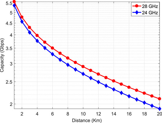
FIGURE 5. Capacity vs. operating frequency for the TB-to-eVTOL link
3.3 Connectivity Using High-Altitude Platforms
Because of their greater flying altitude, high-altitude platforms (HAPs) have broader coverage than TBs. In order to facilitate communication services for an entire eVTOL network in a large coverage area, a network of HAPs must be employed. The HAPs have inter-platform communication links (IPCL) that can be employed either by using millimeter-wave or free-space optical communication. In Miura and Oodo (2001), Miura et al. demonstrate that a network of 16 HAPs can provide coverage to the entire country of Japan.
In addition to the other types of channel losses that we considered for the TBs-to-eVTOL link, in the case of HAP-to-eVTOL links, it is important to model the effect of the elevation angle. The HAP’s higher altitude causes the elevation angle between the HAP and the eVTOL to significantly impact the achievable capacity. To elaborate further, we show the impact of the elevation angle and operating frequency on the capacity of the HAP at 20 km of altitude, communicating with the eVTOL. Figure 6 illustrates that the capacity of the HAP-to-eVTOL link is maximum when the eVTOL is beneath the center point of the HAP; however, when the elevation angle increases or decreases from 90°, the capacity decreases. This is mainly due to the longer path lengths at lower elevation angles, and vice versa. Also, Figure 6 tells us that higher frequencies achieve better capacities; for instance, at a 90° elevation angle, capacities of 0.51 and 0.39 Gbps can be achieved using 28 and 24 GHz frequencies, respectively.
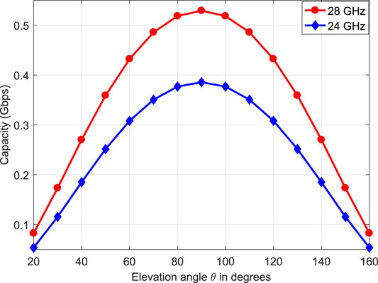
FIGURE 6. Capacity vs. elevation angle for the HAP-to-eVTOL link
3.4 Connectivity Using Satellite Networks
Unlike TBs and HAPs, the altitude of satellites is much higher, ranging from a few hundred kilometers (LEO) to thousands of kilometers (GEO). Due to the higher altitude of the satellites, the path length is far greater than that of TBs and HAPs. Besides longer path lengths, additional losses such as atmospheric, antenna misalignment, and polarization losses affect the satellite-to-eVTOL links. Satellite altitude and the elevation angle between the satellite and the eVTOL also play key roles in designing satellite-to-eVTOL links.
Figure 7 calculates the path length between an eVTOL and satellites at different altitudes (200, 500, and 1000 km). When the satellite is positioned just above the eVTOL at 90° of elevation angle, the path length is at its minimum. However, when the satellite moves toward the horizon, the path length of the satellite-to-eVTOL link grows significantly. For example, in the case of a satellite at 1000 km and 90°, the path length is at the minimum of 1000; however, it reaches approximately 2500 km at 20 and 160°. When the elevation angle is below 10° and above 170°, the visibility between the satellite and eVTOL disappears.
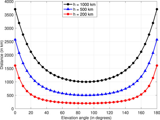
FIGURE 7. Path length of the satellite-to-eVTOL link as a function of satellite altitude and elevation angle.
Figure 8 plots the effect of the satellite elevation angle, operating frequency, and altitude on the path loss of the satellite-to-eVTOL link. For the satellite-to-eVTOL link, we use 1260 MHz and 1090 MHz frequencies in the L-band with three different satellite altitudes (1000, 500, and 200 km) and variable elevation angles. Table 2 specifies the parameters used for the results in this section. Figure 8 suggests that the path loss is minimal at a 90° elevation angle because of the minimum path length; for example, at a 1,260 MHz operating frequency and an altitude of 100 km, the path loss at 90° is 97 dB, whereas at the horizon points (10 or 170°), the path loss reaches around 103 dB. Additionally, the path loss increases at higher operating frequencies; for example, at a fixed elevation angle of 90 and 1000 km altitude, the path loss for 1,260 MHz is 97 dB, while for 1,090 MHz, it is 95 dB, which is 2 dB less. Moreover, due to the greater path length, the path loss increases as the altitude of the satellites increases.
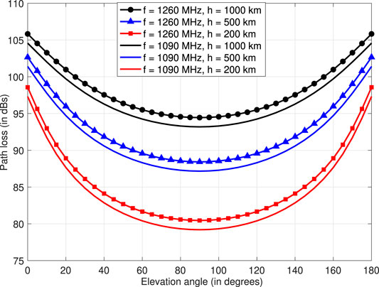
FIGURE 8. Path loss for the satellite-to-eVTOL link in LEO for different frequencies, altitudes, and elevation angles.
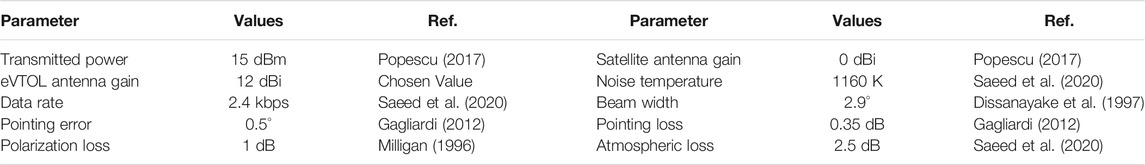
TABLE 2. Parameters of calculating the energy-per-bit to noise spectral density for the satellite-to-eVTOL link.
In Figure 9, we calculate the energy-per-bit to noise spectral density for the satellite-to-eVTOL link against the satellite altitude, elevation angle, and operating frequency. From Figure 9, we can see that the signal quality at the eVTOL depends heavily on these three parameters. As the satellite altitude or operating frequency increases, the signal quality degrades. This is mainly because of the longer path length at higher satellite altitudes and greater signal attenuation at higher frequencies. Also, as mentioned earlier, elevation angles nearer the horizon can lead to lower signal quality. For example, at a fixed operating frequency of 1,260 MHz and satellite altitude of 200 km, 90° of elevation angle results in 18 dB, while 20° only reaches 10 dB, which is 45% less.
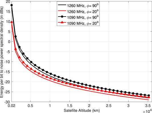
FIGURE 9. Energy-per-bit to noise spectral density for the satellite-to-eVTOL link at varying frequencies, altitudes, and elevation angles.
4 Discussion
We have presented various wireless communication solutions for flying cars. From our assessment, the following key insights can be drawn.
First, existing cellular communication systems do not guarantee seamless aerial coverage and are optimized for on-ground users Azari et al. (2019). For instance, antennas at the base stations (BSs) are tilted toward the ground to generate high antenna gain in that direction, reducing coverage for aerial users. Therefore, on-ground base stations will require significant modifications in order to provide communications to eVTOLs. Establishing ground-to-eVTOL communication links is more challenging than establishing conventional cellular systems that support ground communications because of the different altitude and channel characteristics of eVTOLs. One solution is to equip the ground BSs with extra antennas pointing toward the air, thus improving the aerial coverage. In particular, the three-dimensional massive multiple-input and multiple-output (3D MIMO) technology in 5G is ideally suited to provide aerial coverage for eVTOLs.
Second, tethered balloons have been widely used in the past for meteorological studies, surveillance, and enabling communications for disaster-affected regions. These TBs require lightweight and ultra-strong tethers to support their aerial platforms. These tethers can supply both communication and power capabilities to the TBs. TBs typically operate at the altitude of 200–400 m, making them suitable candidates to provide connectivity to eVTOLs flying at altitudes of around 300 m. There are various types of TBs, depending on their structure and deployment. The most famous among these is the Helikite, which is oblate spheroid in shape and filled with helium. Helikites can operate in harsh weather and support high altitudes because of their robust aerodynamic structure. Figure 2 shows our system model consisting of TBs connected to the ground via tethers, acting as aerial base stations for eVTOLs.
Third, high-altitude platforms present another aerial communication alternative for eVTOLs. Depending on the underlying physical principle used for lifting the airborne vehicle, HAPs can be classified into two major types: aerostatic (lighter than air) HAPs, which use buoyancy to float in the air; and aerodynamic (heavier than air) HAPs, which make use of dynamic forces in the air for stability. HAPs overcome the shortcomings of both satellite and terrestrial communication networks, including small coverage areas, high propagation delays, incremental deployment, and high maintenance costs. Unlike TBs, HAPs operate at higher altitudes in the stratosphere, thus providing wider coverage Mohammed et al. (2011). Current HAP deployments focus only on extending the ground coverage of existing cellular systems, especially in rural areas. In terms of communications, the International Telecommunication Union (ITU) has recently allocated the 24.25–27.5 GHz and the 38–39.5 GHz bands of frequencies for HAPs ITU News (2019).
Last, satellite communications can ensure eVTOL safety by enabling connectivity between satellites and eVTOLs. Generally, ground station controllers use the C-band (4–8 GHz) to communicate with satellites Zolanvari et al. (2020). By contrast, to enable safety communications such as flight plan and weather updates, eVTOLs can communicate with satellites using the L-band (1–2 GHz). In addition, satellite networks can provide real-time position information, including speed, direction, and altitude of the eVTOLs. The satellites report this information to the ground station controller to continuously track eVTOLs. Additionally, in contrast to TBs, HAPs, and cellular networks, satellite networks provide global coverage; therefore, they can also support voice communications in critical scenarios in which the other solutions are out of range. Finally, recent developments in small satellite communication systems operating in low earth orbit (LEO), such as SpaceX Starlink (2020), OneWeb Oneweb (2020), Telesat LEO Telesat (2020), and Kuiper Amazon (2020) can also enable broadband services for the onboard passengers in eVTOLs.
Data Availability Statement
The original contributions presented in the study are included in the article/Supplementary Material; further inquiries can be directed to the corresponding author.
Author Contributions
The work was developed as a collaboration among all authors. NS designed the study and system development. The manuscript was mainly drafted by NS and was revised and corrected by all authors. All authors have read and approved the final manuscript.
Conflict of Interest
The authors declare that the research was conducted in the absence of any commercial or financial relationships that could be construed as a potential conflict of interest.
Acknowledgments
This work was supported by the Office of Sponsored Research (OSR) at King Abdullah University of Science and Technology (KAUST). Figure 2 was produced by Xavier Pita, scientific illustrator at KAUST.
References
Abdi, A., Tepedelenlioglu, C., Kaveh, M., and Giannakis, G. (2001). On the Estimation of the K Parameter for the rice Fading Distribution. IEEE Commun. Lett. 5, 92–94. doi:10.1109/4234.913150
Aeromobil (2020). Aeromobil. https://www.aeromobil.com/ (Accessed April 02, 2020).
Ahmad, I., Md Noor, R., and Reza Z’aba, M. (2019). LTE Efficiency when Used in Traffic Information Systems: A Stable Interest Aware Clustering. Int. J. Commun. Syst. 32, 38–53. doi:10.1002/dac.3853
Airbus (2020). Airbus Vahana. Available at: https://www.airbus.com/innovation/urban-air-mobility/vehicle-demonstrators/vahana.html. (Accessed April 02, 2020).
Amazon (2020). Amazon’s Kuiper Systems Joins SIA. Available at: https://www.satellitetoday.com/business/2019/08/19/amazons-kuiper-systems-joins-sia/ (Accessed: 2020-03-02.
Azari, M. M., Rosas, F., and Pollin, S. (2019). Cellular Connectivity for UAVs: Network Modeling, Performance Analysis, and Design Guidelines. IEEE Trans. Wireless Commun. 18, 3366–3381. doi:10.1109/twc.2019.2910112
Balac, M., Rothfeld, R. L., and Hörl, S. (2019). The Prospects of On-Demand Urban Air Mobility in Zurich, Switzerland. In IEEE Intelligent Transportation Systems Conference. ITSC), 906–913.
Chen, S., Hu, J., Shi, Y., Zhao, L., and Li, W. (2020). A Vision of C-V2x: Technologies, Field Testing and Challenges with Chinese Development. IEEE Internet Things J., 1–20. doi:10.1109/JIOT.2020.2974823
Choi, W., and Hampton, S. (2020). Scenario-based Strategic Planning for Future Civil Vertical Takeoff and landing (VTOL) Transport. J. Aviation/Aerospace Edu. Res. 29, 1–32. doi:10.15394/jaaer.2020.1808
Colpaert, A., Vinogradov, E., and Pollin, S. (2018). Aerial Coverage Analysis of Cellular Systems at LTE and Mmwave Frequencies Using 3D City Models. Sensors 18, 4311. doi:10.3390/s18124311
Dang, S., Amin, O., Shihada, B., and Alouini, M.-S. (2020). What Should 6G Be?. Nat. Electron. 3, 20–29. doi:10.1038/s41928-019-0355-6
Dissanayake, A., Allnutt, J., and Haidara, F. (1997). A Prediction Model that Combines Rain Attenuation and Other Propagation Impairments along Earth-Satellite Paths. IEEE Trans. Antennas Propagat. 45, 1546–1558. doi:10.1109/8.633864
FCC (1997). Millimeter Wave Propagation: Spectrum Management Implications. Fed. Commun. Comission (Technical report.
Giordani, M., Polese, M., Mezzavilla, M., Rangan, S., and Zorzi, M. (2020). Toward 6G Networks: Use Cases and Technologies. IEEE Commun. Mag. 58, 55–61. doi:10.1109/mcom.001.1900411
Goddemeier, N., and Wietfeld, C. (2015). Investigation of Air-To-Air Channel Characteristics and a UAV Specific Extension to the rice Model. In IEEE Globecom Workshops (GC Wkshps). 1–5. doi:10.1109/glocomw.2015.7414180
Grace, D., Jiang, T., Allsopp, S., Reynaud, L., and Mohorcic, M. (2011). European Commission’s Seventh Framework Programme (Technical report).
GSMA (2019). 26 GHz and 28 GHz Are Both Needed for 5G. Available at: https://www.gsma.com/spectrum/resources/26-ghz-28-ghz/.Online (accessed Dec 19, 2019).
Hawk, K. (2020). Kitty Hawk Cora. Available at: https://kittyhawk.aero/ (Accessed: 2020-04-02.
HTCL (2019). Trial of 5G Base Station and User Equipment Operating at 26/28 GHz Bands and 3.5 GHz Band. Hutchison Telephone Company Limited (Technical report).
ITU News (2019). WRC-19 Identifies Additional Frequency Bands for High Altitude Platform Station Systems. Geneva: ITU. Available at: https://news.itu.int/wrc-19-identifies-additional-frequency-bands-for-high-altitude-platform-station-systems/.
Kasliwal, A., Furbush, N. J., Gawron, J. H., McBride, J. R., Wallington, T. J., De Kleine, R. D., et al. (2019). Role of Flying Cars in Sustainable Mobility. Nat. Commun. 10, 1–9. doi:10.1038/s41467-019-09426-0
Khuwaja, A. A., Chen, Y., Zhao, N., Alouini, M.-S., and Dobbins, P. (2018). A Survey of Channel Modeling for UAV Communications. IEEE Commun. Surv. Tutorials 20, 2804–2821. doi:10.1109/comst.2018.2856587
Milligan, T. (1996). Polarization Loss in a Link Budget when Using Measured Circular-Polarization Gains of Antennas. IEEE Antennas Propag. Mag. 38, 56–58. doi:10.1109/74.491291
Miura, R., and Oodo, M. (2001). Wireless Communications System Using Stratospheric Platforms. J. Commun. Res. Lab 48, 33–48.
Mohammed, A., Mehmood, A., Pavlidou, F.-N., and Mohorcic, M. (2011). The Role of High-Altitude Platforms (HAPs) in the Global Wireless Connectivity. Proc. IEEE 99, 1939–1953. doi:10.1109/jproc.2011.2159690
Moore, M. D., Goodrich, K. H., Viken, J., Smith, J. C., Fredericks, B., Trani, T., et al. (2013). High Speed Mobility through On-Demand Aviation. InAIAA Technical Conference. 1–27. doi:10.2514/6.2013-4373
Nizzi, F., Pecorella, T., Caputo, S., Mucchi, L., Fantacci, R., Bastianini, M., et al. (2019). Data Dissemination to Vehicles Using 5G and VLC for Smart Cities. AEIT Int. Annu. Conf., 1–5. doi:10.23919/AEIT.2019.8893380
Oneweb (2020). Whereever You Are, We Will Cover You. Available at: https://oneweb.world (Accessed: 2020-03-02.
Pan, G., and Alouini, M.-S. (2021). Flying Car Transportation System: Advances, Techniques, and Challenges. IEEE Access 9, 24586–24603. doi:10.1109/access.2021.3056798
Popescu, O. (2017). Power Budgets for Cubesat Radios to Support Ground Communications and Inter-satellite Links. IEEE Access 5, 12618–12625. doi:10.1109/access.2017.2721948
Rajashekara, K., Wang, Q., and Matsuse, K. (2016). Flying Cars: Challenges and Propulsion Strategies. IEEE Electrific. Mag. 4, 46–57. doi:10.1109/mele.2015.2509901
Saeed, N., Elzanaty, A., Almorad, H., Dahrouj, H., Al-Naffouri, T. Y., and Alouini, M.-S. (2020). Cubesat Communications: Recent Advances and Future Challenges. IEEE Commun. Surv. Tutorials 22, 1839–1862. doi:10.1109/comst.2020.2990499
Starlink (2020). SpaceX Submits Paperwork for 30,000 More Starlink Satellites. Available at: https://spacenews.com/spacex-submits-paperwork-for-30000-more-starlink-satellites/ (Accessed: 2020-03-02).
Sutherland, B. R. (2019). Flying Cars for green Transportation. Joule 3, 1187–1189. doi:10.1016/j.joule.2019.04.013
Telesat (2020). Telesat LEO-Why LEO?. Available at: https://www.telesat.com/services/leo/why-leo (Accessed: 2020-03-02).
Terrafugia (2020). Terrafugia. Available at: https://terrafugia.com/ (Accessed: 2020-04-02).
Toyota (2020). SkyDrive. Available at: http://cartivator.com/ (Accessed: 2020-04-02).
Uber (2020a). Uber Air. Available at: https://www.uber.com/us/en/elevate/uberair/ (Accessed: 2020-04-02).
Uber (2020b). Uber and AT&T Testing 5G for Flying Cars. Available at: https://www.zdnet.com/article/uber-and-at-t-testing-5g-for-flying-cars/ (Accessed: 2020-04-02).
Ullman, D. G., Homer, V., Horgan, P., and Ouellete, R. (2017). Comparing Electric Sky Taxi Visions. Technical reportdoi:10.5194/gmd-2016-220-ac1
Wang, J., Liu, J., and Kato, N. (2019). Networking and Communications in Autonomous Driving: A Survey. IEEE Commun. Surv. Tutorials 21, 1243–1274. doi:10.1109/comst.2018.2888904
Yaqoob, I., Khan, L. U., Kazmi, S. M. A., Imran, M., Guizani, N., and Hong, C. S. (2020). Autonomous Driving Cars in Smart Cities: Recent Advances, Requirements, and Challenges. IEEE Netw. 34, 174–181. doi:10.1109/mnet.2019.1900120
Zhou, H., Xu, W., Chen, J., and Wang, W. (2020). Evolutionary V2X Technologies toward the Internet of Vehicles: Challenges and Opportunities. Proc. IEEE 108, 308–323. doi:10.1109/jproc.2019.2961937
Keywords: transportation systems, electric vertical takeoff and landing aircrafts, wireless communication, tethered balloons, high-altitude platforms, satellites
Citation: Saeed N, Al-Naffouri TY and Alouini M-S (2021) Wireless Communication for Flying Cars. Front. Comms. Net 2:689881. doi: 10.3389/frcmn.2021.689881
Received: 01 April 2021; Accepted: 17 May 2021;
Published: 04 June 2021.
Edited by:
Pankaj Kumar Sharma, National Institute of Technology Rourkela, IndiaReviewed by:
Devendra Singh Gurjar, National Institute of Technology, IndiaSourabh Solanki, Korea University, South Korea
Essaid Sabir, University of Hassan II Casablanca, Morocco
Copyright © 2021 Saeed, Al-Naffouri and Alouini. This is an open-access article distributed under the terms of the Creative Commons Attribution License (CC BY). The use, distribution or reproduction in other forums is permitted, provided the original author(s) and the copyright owner(s) are credited and that the original publication in this journal is cited, in accordance with accepted academic practice. No use, distribution or reproduction is permitted which does not comply with these terms.
*Correspondence: Nasir Saeed, bXIubmFzaXIuc2FlZWRAaWVlZS5vcmc=