A varactor-based 1024-element RIS design for mm-waves
 Luis G. da Silva
 Z. Chu2
  Pei Xiao
 Arismar Cerqueira S
 - 1Laboratory WOCA (Wireless and Optical Convergent Access), National Institute of Telecommunication (Inatel), Santa Rita do Sapucai, MG, Brazil
- 22ICS, 5GIC & 6GIC, The University of Surrey, Guildford, United Kingdom
This paper reports a reconfigurable intelligent surface (RIS) for beamforming and beam steering applications operating in the millimeter wave (mm-waves) frequency band. The proposed 2-bit RIS design is implemented using a radar cross-section (RCS) approach in ANSYS HFSS for performance evaluation and system-level analysis. It is based on split-ring resonator (SRR) unit cells, tuned by varactor diodes, comprising 1,024 elements arranged in a 32 × 32 matrix with linear gradient phase configuration operating at 24.5 GHz over the fifth generation of mobile communications New Radio (5G NR) frequency range 2 (FR2). A beam steering from −60° to 60° in the azimuth plane is demonstrated for mm-waves coverage extension. Numerical simulations of RCS patterns from −10° to −60° and from 10° to 60° with approximately 3 dB scan loss manifest the applicability of the proposed RIS towards the sixth generation of mobile communications (6G). Furthermore, simulated results of angular reciprocity prove the RIS response up to 110° under an oblique incident wave at 60°. To the best of our knowledge, this is the highest RIS angular reciprocity reported in the literature, validating its application to coverage extension from −60° to 60°. In addition, the RCS level and reflected angle relationship are modeled for system-level analysis purposes.
1 Introduction
Recently, reconfigurable intelligent surfaces (RISs) have gained increasing attention as an emergent technology for future wireless communication systems, such as beyond the fifth-generation (B5G) and sixth-generation (6G) of mobile communications (Bariah et al., 2020). This technology has also been referenced as Intelligent Reflecting Surface (IRS) (Wu et al., 2021), Large Intelligent Surface (LIS) (Liang et al., 2019), Smart Radio (Di Renzo et al., 2019), software-controlled metasurface (Liaskos et al., 2018), and holographic multiple-input multiple-output (MIMO) surfaces (HMIMOS) (Huang et al., 2020). Nevertheless, efforts have been made by the European Telecommunications Standards Institute (ETSI) in the form of an industry specification group (ISG) for RIS standardization (Reconfigurable intelligent surfaces standardization, 2022). RISs can create a smart wireless environment by applying reconfigurable metasurfaces without power-consuming electronics and RF amplifiers. Such passive reflecting surfaces can be easily deployed to extend wireless coverage and provide connection in non-line-of-sight (NLoS) conditions. Additionally, the use of RIS is envisioned for other applications, namely,: channel capacity (Perović et al., 2020); mobile edge computing (Bai et al., 2021); relaying systems (Di Renzo et al., 2020a); secure communications (Chu et al., 2020); rank improvement in MIMO communications (Özdogan et al., 2020); reflection pattern modulation in the multiple-input single-output (MISO) system (Lin et al., 2021); artificial intelligence (Gacanin and Di Renzo, 2020), etc.
RISs are based on sub-wavelength unit cells arranged in a planar manner. Generally, these elements are based on printed circuit boards (PCBs) to take advantage of their benefits and technological readiness. The unit cell reflection coefficient might be altered by embedded tuning elements, such as PIN and varactor diodes, easily integrated into the PCB technology. Moreover, liquid crystal (Foo, 2017), Micro-Electro-Mechanical Switches (MEMS) switches (He et al., 2019), integrated circuit (IC) (Pitilakis et al., 2021), mechanical reconfiguration (Kitayama et al., 2021), and advanced materials such as graphene (BiswasGutierrez et al., 2018) might be applied. Early works on the concept of RIS from late 2003 can be found in (Kuester et al., 2003) and (Holloway et al., 2005), showing the notion of metafilm to control reflection or transmission properties, enabling its application to design antennas, reflectors, and controlled scattered surfaces to form a smart surface. Later, in 2009, reflectarray technology was presented to enable communications between a base station and mobile users under blind spot conditions (Li et al., 2009). Subrt et al. (2010) started introducing the concept of intelligent walls to control the propagation of electromagnetic waves in indoor scenarios in 2010. In that case, the authors proposed using surfaces with active frequency selective surface (FSS) elements and monitoring sensors to control the propagation environment according to traffic demand. Since then, many works have been published in RIS based on PCB solutions with PIN and varactor diodes as tuning elements and patch reflectors (Trichopoulos et al., 2022)- (Araghi et al., 2022). To generate the unit cell reflection phase tunability, patch elements might be connected to parasitic elements (Trichopoulos et al., 2022), (Gros et al., 2021), grounded elements (Pei et al., 2021), (Rains et al., 2021), or between them (Araghi et al., 2022). Also, a different approach was proposed in (Dai et al., 2020) based on a top patch element interaction with a slot-loaded plane between it and the ground plane.
Regarding the unit cells phase tunability range, most papers applied the 1-bit approach (0° and 180°) to conceptualize a RIS for spherical incident wave excitation (near-field) due to its simplicity. For example, a unit cell at 5.8 GHz controlled by PIN diodes was proposed in (Trichopoulos et al., 2022) for two phase states generation producing beamforming response. Authors showed the RIS beamforming response behavior by changing from spherical to plane incident wave excitation (far-field), wherewith the latter a two symmetric beam split occurs. Similarly, the reference (Gros et al., 2021) presented a square patch with PIN diodes for mm-waves. The PIN diode was responsible for connecting the patch element to parasitic stubs, producing a phase difference of 180° at 28.5 GHz. Additionally, the presented structure provides a dual-polarization operation for spherical incident waves, generating reflected single beams.
Differently from the previous works, Pei et al. (2021) in reported a varactor-based 1-bit unit cell composed of two tuning elements to produce the 180° phase difference at 5.8 GHz. By using varactor diodes, one can smoothly tune the phase states to generate the desired phase shift with negligible power consumption. Furthermore, by increasing the number of phase states between 0° and 360°, the beam-splitting effect can be eliminated regardless of the incident plane waves. Aiming to increase the number of phase states using PIN diodes, five devices were arranged into a slot-loaded plane in (Dai et al., 2020), producing four different 90° apart phase states to compose a 2-bit unit cell at 2.3 GHz and another one at 28.5 GHz. The number of phase states was improved by introducing a unit cell with five patches connected by three PIN diodes and one lumped capacitor (Rains et al., 2021). In this way, a 3-bit unit cell with eight distinct phase states biased in a column-wise fashion was demonstrated. Finally, two D-shape patches connected with a varactor diode for tuning the unit cell reflection phase up to 300° at 3.5 GHz was reported in (Araghi et al., 2022).
This paper presents a 1024-element RIS design using SRR-based unit cells tuned by varactor diodes for mm-waves. It generates reconfigurable reflected beams from incident plane waves by changing the metasurface phase profile. The unit cells operate at 24.5 GHz with 2-bit phase states arranged in a 32 × 32 matrix, resulting in 1,024 individually biased elements. The introduced RIS can operate with single-beam reflection or multi-beam configurations with sector regions and incident plane waves. Section 2 presents the theoretical foundation and design procedure of the proposed RIS, including the unit cell design. The performance of RIS applied to wireless communication systems is discussed in Section 3. Conclusions and final comments are elucidated in Section 4.
2 RIS design for mm-waves
2.1 Unit cell design
The proposed mm-waves RIS has been designed for coverage extension applications in indoor and outdoor scenarios. The key feature of RIS responsible for providing reconfigurability is the unit cell reflection coefficient response. Therefore, we have defined the following RIS and unit cell design specifications: 24.5 GHz central frequency and 400 MHz bandwidth, i.e., the band n258 from the 5G NR FR2 (3GPP et al., 2018); scanning area of ±60° for the azimuth and elevation planes. Furthermore, for incident plane waves (far-field) operation, we have established a 2-bit phase response with a phase shifting from 0° to 270°. Lastly, the proposed RIS has 1,024 elements with an approximately 8λ2 area, aiming for beamforming (Yang et al., 2017) and RIS-empowered mm-waves communication systems (Basar et al., 2021).
The unit cells are subwavelength components with reflective behavior that can be associated to form a two-dimensional structure, named as metasurface. By properly designing and associating unit cells, the achieved metasurface might have unnatural properties for controlling electromagnetic waves (Glybovski et al., 2016). Moreover, by adding a control mechanism to the unit cells, the resultant metasurface can be programmed to the desired functionality (Abadal et al., 2020). We have used resonant unit cells with tunable phases across a central frequency to produce a resonant metasurface (Cui et al., 2009).
Recently, we have proposed a unit cell based on frequency selective surface (FSS) with 180° phase tuning for 1-bit RIS applications (da Silva and Arismar Cerqueira, 2021). However, for the current work operating with an incident plane wave, the designed unit cell should have at least a 2-bit quantization phase scheme to avoid beam splitting (Yin et al., 2020). Also, compared to a 3-bit method with increased bias control complexity, the loss is less than 1 dB for the 2-bit case (Wu et al., 2008). Therefore, the applied unit cell is based on our previous work from (da Silva and Xiao, 2022). Instead of using classical patch reflectors (Trichopoulos et al., 2022)- (Araghi et al., 2022) as reflective elements, the current RIS design is based on SRRs. The SRRs composed of thin metallic rings or square loops with a split on the top of a dielectric substrate have been commonly used as a building block for metamaterials at microwave and terahertz frequencies (Chen et al., 2016). Many variations have been proposed for those resonators, such as single rings, double rings, broadside coupled rings, complementary split rings, and multiply split rings (Sydoruk et al., 2009).
Figure 1 illustrates the single-band electrically resonant SRR unit cell. A varactor diode was inserted at the main resonator arm to tune the resulted unit cell because the incident plane wave has an x-oriented electrical field. The unit cell comprises a periodic square structure (p) and a circular resonator with its central trace connected by a varactor diode in the middle. A solid ground plane is introduced at the bottom layer. We have used the MAVR-000120-14110P varactor model from MACOM with capacitance ranging from 0.23 to 0.9pF; this component has been modeled as a lumped RLC boundary condition in ANSYS HFSS. The SRR numerical model, conceived in ANSYS HFSS using the dielectric substrate Rogers RO3003 (εr = 3, tanδ = 0.001, and t = 0.508 mm), was based on periodic boundary conditions and Floquet ports to determine the unit cell reflection coefficient. Initially, the SRR dimensions were tuned to obtain an electrical length of about half wavelength at 24.5 GHz for the resonator perimeter with a period p close to a quarter wavelength. After the varactor insertion, the SRR design parameters were updated to tune the unit cell resonance frequency from 22.7 to 25.6 GHz. Also, aiming to improve the unit cell reflection phase response, asymmetric resonator arms mapped by α1 and α2 were tuned to increase the phase shift to 270° according to the varactor diode capacitance. The unit cell final dimensions are: p = 3 mm, Ls = 1.28 mm, g = 0.26 mm, Ws = 0.4 mm, α1 = 32.25° and α2 = 21.52°.

FIGURE 1. Unit cell based on SRR. (A) Perspective view. (B) Top view.
Figure 2 summarizes the unit cell simulated reflection coefficient results from 22 to 27 GHz, and the curves are labeled as a function of the varactor capacitance. By tuning the unit cell resonance frequency, the reflection phase at 24.5 GHz was shifted from 91.33° to −178.69°, producing a 270° phase shift as reported in Figure 2B. Since the unit cell has been designed to work as a reflective component, a reflection amplitude lower than 0 dB represents reflection losses due to the dielectric, metallic, ohmic, and varactor losses. Therefore, Figure 2C illustrates the unit cell reflection loss at 24.5 GHz as a function of varactor capacitance for four conditions. The curve named full model represents the results from Figure 2A and has a maximum reflection loss close to the resonance frequency (24.5 GHz) near 0.36 pF. By removing the dielectric losses, the result at this frequency improves by about 5%, and for a perfect conductor instead of copper, the reflection loss improvement rises to 10%. Since the reflection loss is not pronounced out of resonance, the dielectric and metallic losses influence are reduced for capacitance values above and below 0.36 pF. Nevertheless, a reflection loss improvement of roughly 82% at resonance can be achieved by removing the varactor losses (resistance), even for the entire capacitance range from 0.23 to 0.9 pF an improvement is noticeable. Thus, further optimization of the proposed unit cell reflection loss can be managed using low-loss varactor diodes.
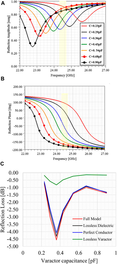
FIGURE 2. Unit cell simulated reflection coefficient. (A) Reflection amplitude. (B) Reflection phase. (C) Reflection loss at 24.5 GHz.
A 2-bit unit cell can be generated by producing four different phase states which are 90° apart from each other. Consequently, four configuration states are ensured by tuning the varactor diode capacitance, namely,: 0.9, 0.38, 0.31, and 0.23 pF. The configurations from 1 to 4 are shown in Figure 3. Regarding the reflection amplitude, the lowest obtained value was −4.15 dB for configuration state 3 and higher than −1.5 dB for configuration states 1 and 4. Compared to the previous references (Trichopoulos et al., 2022)- (Araghi et al., 2022), the proposed unit cell has a higher loss than the 1-bit unit cell presented from (Trichopoulos et al., 2022) and the 2-bit unit cell from (Dai et al., 2020), although both unit cells operate at lower frequencies. The 1-bit unit cell at 28.5 GHz from (Gros et al., 2021) showed a maximum reflection amplitude of -3 dB using PIN diodes, whereas the one from (Rains et al., 2021) can generate a 3-bit phase response with −4.65 dB maximum reflection amplitude at 3.75 GHz. The unit cells from (Pei et al., 2021) and (Araghi et al., 2022) used varactor diodes as tuning elements at 5.8 and 3.5 GHz, respectively. As a result, the maximum reflection amplitude was 6 dB in (Pei et al., 2021) and 3 dB in (Araghi et al., 2022), which is close to the proposed unit cell. The reflection amplitude variation influences the RIS reflected beam pattern and amplitude. As different reflected beams will produce a particular phase distribution and, consequently, an amplitude distribution, its effects will depend upon the configuration. The unit cell phase state close to resonance presents the lower reflection amplitude value and contributes mainly to the beam pattern losses. Combining these high and low reflection amplitude values across the RIS produces main beam losses and variation in side lobe level (SLL). Therefore, the proposed SRR-based unit cell shows a performance close to the reference works with a 2-bit phase quantization scheme at mm-waves. The significant contribution of reflection amplitude losses can be attributed to the varactor resistance, a commercial off-the-shelf (COTS) component.
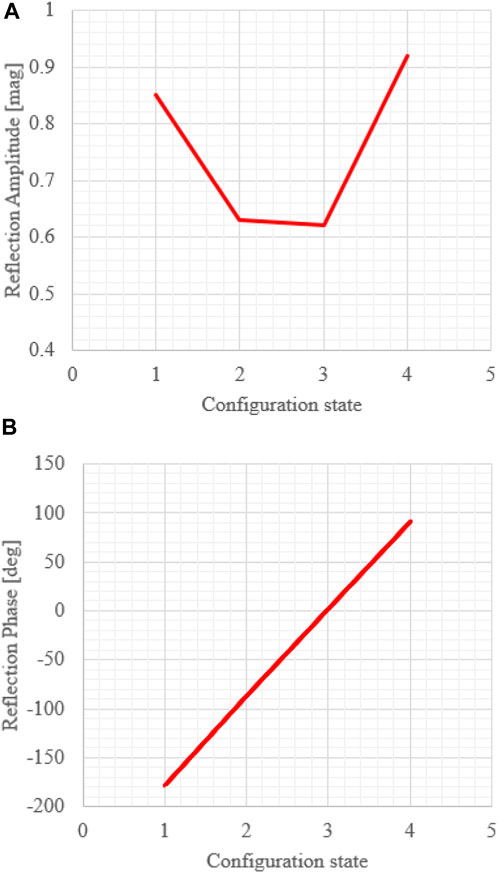
FIGURE 3. Unit cell configuration states at 24.5 GHz. (A) Reflection amplitude. (B) Reflection phase.
Additionally, our 2-bit unit cell uses single varactor diodes that simplify the bias lines and control stage. Consequently, a unique bias line arranged over a 3 mm2 area ensures 2-bit phase states. For example, the designs from (Trichopoulos et al., 2022) and (Gros et al., 2021) use single PIN diodes and bias lines, thus an increase in the phase states requires more bias lines. In (Dai et al., 2020), the 2-bit unit cell based on PIN diodes needs five components and two bias lines in each unit cell, increasing the design complexity at mm-waves. Similarly, a 3-bit unit cell using three PIN diodes was presented in (Rains et al., 2021), one capacitor, and three bias lines to generate the phase states at 3.75 GHz. Therefore, we can increase the unit cell tuning range with a single component and bias line by using varactor diodes as a tuning element. Also, the RIS power consumption can be significantly reduced by applying varactor diodes instead of PIN diodes (Pei et al., 2021).
2.2 Principle of operation and applications
Briefly, the RIS structure illustrated in Figure 4A comprises a metasurface layer with unit cells and tuning elements, a copper plane to increase reflectivity and avoid interference, and a control circuit board for biasing and tuning the unit cell response. The RIS intelligent controller is typically implemented using field-programmable gate array (FPGA) boards (Wu and Zhang, 2020). The RIS comes from the reflectarray antenna theory using two-dimensional structures to form a metasurface. The metasurface encompasses a combination of subwavelength unit cells with controllable properties for shaping the reflected wave phase and/or amplitude (Gong et al., 2020). Thus, a RIS can shape and manipulate the reflected electromagnetic wave to modify the propagation environment toward a smart radio concept (Wu and Zhang, 2020). Furthermore, the RIS can be designed to operate at the far-field regime to enable beamforming and beam steering or in the near-field condition to improve coverage area (Tang et al., 2021). Figure 4B presents some RIS operation modes according to the configured phase profile and excitation wave: reflection, transmission/refraction, absorption, focusing/beamforming, polarization converter, collimation, splitting, and analog processing (Di Renzo et al., 2020b).
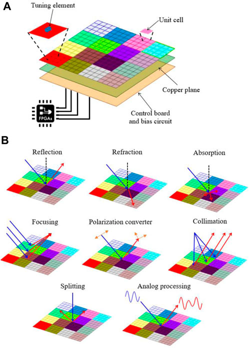
FIGURE 4. Reconfigurable intelligent surface. (A) Structure layers. (B) Operation modes.
As the 5G mobile network has started to be deployed since 2020, new demands and opportunities are foreseen. The research community has begun discussing the key drivers, requirements, and technologies for B5G and 6G solutions (Pan et al., 2021). Following the trend started by 5G, high-frequency usage will continue to increase beyond mm-waves for incorporating the THz band. Although the use of higher frequency bands for the next generations of wireless communications will bring many opportunities, there has been a concern about its propagation, both indoor and outdoor. However, employing higher frequency bands implies reduced coverage area and blockage conditions due to the high gain and narrow beamwidth antennas to overcome the propagation losses. The emerging theme of RIS represents a way to tackle this issue by treating the propagation environment, which is highly probabilistic, in a software-controllable manner. Despite the interest in RIS applications for high-frequency bands, its development has been conducted at lower frequencies so far (Trichopoulos et al., 2022)- (Araghi et al., 2022), albeit theoretical studies have been done for the THz band (Wan et al., 2021). The use of mm-waves has been considered as one key enabler for 5G systems and beyond, including 6G (Hong et al., 2021). In this context, RIS and mm-waves are expected to bring opportunities, application scenarios, and maturity to RIS development (Nemati et al., 2020)- (He et al., 2020). In addition, RIS represents a complementary alternative to massive MIMO (mMIMO) systems that incur a significant amount of power consumption and implementation costs due to a large number of elements (Shojaeifard et al., 2022). Although mMIMO techniques could mitigate path loss and multipath channels, they fail to overcome the blockage problem. Increasing the number of base stations with MIMO might reduce blockage, but it represents a costly solution. Thus, RIS introduces a key enabling technology to cope with these issues (Pan et al., 2021). The performance analysis for mMIMO and RIS operating in different scenarios was shown in (Björnson and Sanguinetti, 2020).
The application of RIS to mm-waves cellular networks can improve the signal-to-interference ratio. Its deployment is more effective as the number of mm-waves base stations increases (Nemati et al., 2020). Also, optimization schemes in the phase adjustment of RIS elements can improve channel capacity for mm-waves indoor scenarios under non-line-of-sight (NLoS) conditions (Perović et al., 2020). Similarly, reconfigurable smart reflectarrays at 60 GHz were proposed for indoor networks for cases where obstructions block the line-of-sight (LoS) path (Tan et al., 2018). The proposed solution was experimentally validated and evaluated using a beam-searching algorithm to minimize the link outage probability. Moreover, joint active and passive precoding for RIS-assisted mm-waves systems was proposed in (Wang et al., 2020) to maximize the received signal from a base station to a single-antenna receiver by optimizing the base station transmitted precoding vector and RIS phase profile. RISs can also be combined with mm-waves MIMO systems for positioning and object tracking applications. RIS-aided systems allow enhanced position estimation accuracy performance according to its number and phase shift values (He et al., 2020).
Figure 5 summarizes the application scenarios envisioned for the proposed mm-waves RIS. First, it is presented a NLOS scenario resulting from signal blockage and/or high attenuation. Thus, using RIS at strategic places can provide the desired connection through a virtual LoS (VLoS) link. The RIS can be installed on windows or facades in outdoor environments, providing a VLoS connection to unreachable shadow zones. Another application is the RISs implementation as a relay technology between transmitter and receiver. The RIS relay is based on passive reflection of the incoming signal with no additional RF power consumption, operating in a full-duplex manner (Wu and Zhang, 2020)- (Gong et al., 2020). In addition, the advantages of the RIS relay include low cost and complexity, easy deployment, RF chain-free, and being unaffected by receiver noise (Basar et al., 2019). The RIS can be used for indoor applications to support the connection from the outside to the inside environment, as for mm-waves frequencies, indoor obstacles, and wall attenuation can be higher than 30 dB (Rappaport et al., 2017). Similarly, RISs can overcome dead zones and extend the coverage in highly obstructed indoor scenarios. Another way to apply RISs in indoor environments might be using their multi-beam capabilities for multi-user coverage at different locations.

FIGURE 5. RIS application scenarios for coverage improvement.
2.3 RIS design procedure
The RIS functionality relies on the unit cell response and tunability in terms of reflection phase to generate the desired reflected electromagnetic wave in programmable wireless environments. The RIS phase states can be configured in a linear gradient, concentric gradient, angular gradient, or random pattern, creating anomalous reflection, focusing, vorticity or diffuse scattering, respectively (Cui et al., 2009). Therefore, by properly designing the unit cell, a single RIS might enable multiple functionalities. This work is focused on RIS with linear gradients, using incident plane waves as input for anomalous reflection and beam-steering functions.
The RIS can be viewed as an extension of the well-known reflectarray antennas with plane wave excitation or classical metasurface using generalized Snell reflection law to produce anomalous reflections. This work is based on the former option, which can operate with spherical or plane waves and presents simple control and modeling. Conversely, the later approach defines the metasurface 2π period as a function of the incident angle, wavelength, and reflected angle (Díaz-Rubio et al., 2017). Thus, it demands the use of unit cells with continuous 360° phase response, increasing the RIS complexity. Also, electrically large metasurfaces (>80 λ2) are required for reflection angles higher than 50° (Islam and Choi, 2020).
Figure 6 shows the RIS representation to determine phase distribution along the xy axis for ϕ and θ angles. The RIS has MxN elements with a d-squared area each. In order to produce the desired beam steering, each unit cell reflection phase is given by
where Φrmn is the phase delay required to produce a reflected beam at (θr, ϕr) direction, when the RIS is excited by a plane wave at (θ0, ϕ0) direction generating the phase distribution Φ0mn. Thus, the phase distributions are given by (Huang and Encinar, 2008)
where k0 is the free space wavenumber and (xm,yn) is the unit cell coordinates along the RIS. The calculated phase matrix Φmn represents the continuum phase distribution that will be quantized with 2-bit resolution, generating the phase matrix Φqmn. Considering a 32 × 32 RIS with the proposed unit cell, normal incident plane wave and desired beam steering at (30°, 0°), the calculated phase distribution for each element according to (1) is reported in Figure 7 for continuous and 2-bit phase distribution. The reflected beam shape and pointing angle are obtained by applying the phase distribution to the array factor. The RIS array factor is determined using uniform planar array theory as (Balanis, 2016)
where unit cells with the same reflection amplitude are considered for the sake of simplicity.
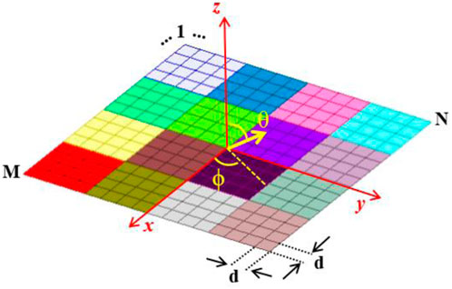
FIGURE 6. RIS representation for phase distribution definition.
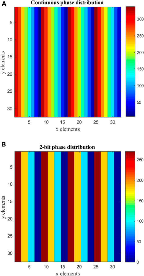
FIGURE 7. RIS phase distribution for beam steering at 30°. (A) Continuous phase. (B) 2-bit quantization.
Figure 8 shows the array factor calculated using the phase distributions from Figure 7 for continuous and 2-bit cases. It is worth noting that both phase distributions produce the desired beam steering angle; a slight amplitude reduction was observed in the 2-bit phase condition. Additionally, both curves present similar SLLs, mainly those close to the main beam. Some side lobes might have a considerable level for high beam steering angles using 2-bit phase distributions; however, it can be mitigated by adding an extra pseudo-random phase distribution (Kashyap et al., 2020).
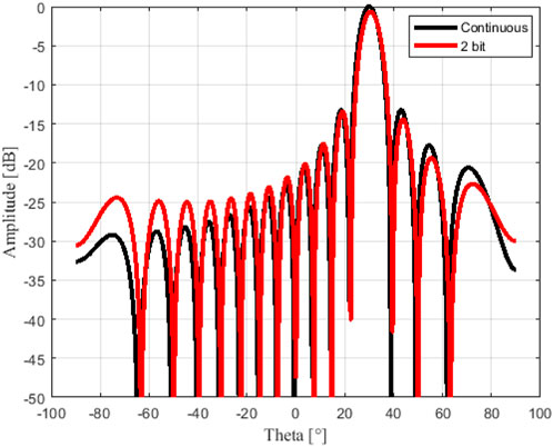
FIGURE 8. RIS array factor for beam steering at 30°.
Moreover, Figure 9 presents the array factor performance parameters for different quantization bits as a function of the reflected angle for a 32 × 32 RIS with normal incident plane wave and reflected beam at (θr, 0°). As presented in Figure 9A, increasing the quantization bit number reduces the quantization phase error compared to the continuous phase case. This parameter influences the RIS performance in terms of losses, beam pointing error, and side lobe level. However, a considerable difference in the quantization phase error is noticeable only from the 1-bit to 2-bit case, whereas the difference is reduced from the 2-bit to 3-bit quantization. The quantization loss is the most affected parameter, as Figure 9B depicts. Since the 1-bit quantization phase produces grating lobes, its losses are greater than 3 dB for some configurations, reducing to roughly 0.9dB and 0.2 dB for the 2-bit and 3-bit cases, respectively. Furthermore, the beam pointing error decreases with the quantization bit number, Figure 9C. Although the 3-bit alternative presents the slightest variation, it is close to the 2-bit response, which represents a simple design. Lastly, Figure 9D summarizes the SLL performance for the three quantization bits schemes as a function of the reflected angle. The 0 dB SLL attributed to the 1-bit quantization is due to the symmetrical lobe presented at -θr for each configuration. In contrast, SLLs greater than 12 dB is obtained for higher quantization bit numbers despite the worse performance for the 2-bit scheme at reflected angles lower than 20°. In summary, the 2-bit quantization design (rather than the 3-bit design) is justified due to its comparable performance and simple implementation.
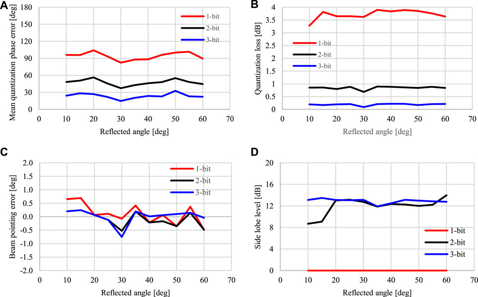
FIGURE 9. RIS array factor performance for different quantization bits. (A) Mean quantization phase error. (B) Quantization loss. (C) Beam pointing error. (D) Side lobe level.
The unit cell size is another important parameter for the array factor performance evaluation. Considering a maximum RIS dimension of 96 mm × 96 mm, the sizes 0.1λ (1.22 mm), 0.245λ (3 mm), and 0.5λ (6.12 mm) were evaluated for the 2-bit quantization phase. Figure 10 shows the beam pointing error and SLL curves as a function of the reflected angle (θr, 0°) for normal incident plane wave. In short, both parameters improve with unit cell size reduction, especially the beam pointing error of less than 0.25° for 0.1λ unit cell. However, the 0.245λ unit cell selection is justified by its similar performance compared to the 0.1λ unit cell and available area for bias lines routing in the final design. Although the 0.5λ unit cell gives a larger area for design, its performance degradation is more pronounced than the 0.245λ unit cell.
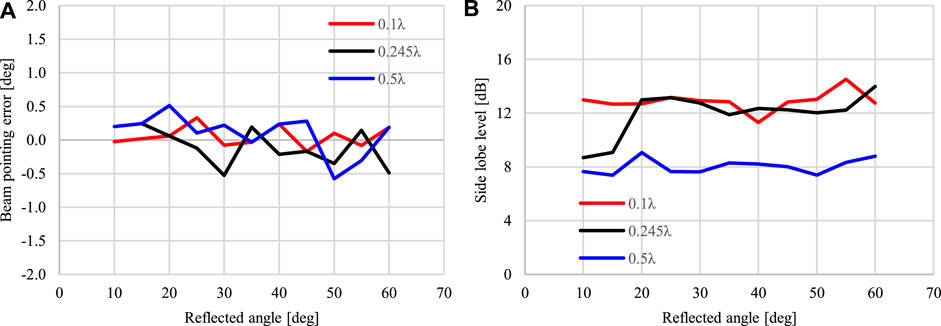
FIGURE 10. RIS array factor performance for different unit cell sizes. (A) Beam pointing error. (B) Side lobe level.
We have used the ANSYS HFSS full-wave solver to create the RIS numerical model and evaluate its response for different phase distributions. The simulation using the conventional finite element method (FEM) requires high computational effort due to the RIS large electrical size (≈8λ2) and many subwavelength details. For this reason, we have used the finite array domain decomposition method (FADDM) with 3D components to optimize simulation time and maintain the simulation accuracy. The RIS numerical model using this solver technique is depicted in Figure 11. The four highlighted unit cells represent the different phase states arranged in a 32 × 32 matrix, using the mesh assembly technique. The obtained RCS patterns allow evaluation of the RIS reflective response under different phase distribution schemes.
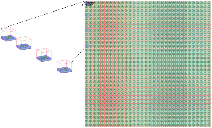
FIGURE 11. ANSYS HFSS model for the proposed RIS.
The phase distribution determined by Eqs. 1, 2 has been configured in the RIS model, considering the incident wave parameters (0°, 0°) and reflected beam θr from −60° to 60° and ϕr = 0°. The simulated RCS patterns in the xz plane are given in Figure 12. A beam scanning from −60° to 60° with a 10° step is reported for the proposed RIS, with the main beam response symmetrical at both angle orientations. As expected, the RCS pattern peak decreases as the reflection angle increases, producing a scan loss with cosine function behavior (Nayeri et al., 2018). The RCS peak level varies from 5 to 2.1 dBsm for beam steering angles from 10° to 60°, roughly representing a 3 dB scan loss. For the beam steering at the negative side, the RCS peak levels are 5.17 and 2.12 dBsm for the minimum and maximum steering angle, respectively. In summary, the proposed RIS has been numerically validated under normal incident plane waves and beam scanning from −60° to 60°.
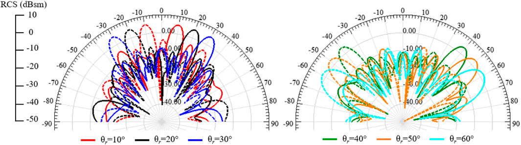
FIGURE 12. Simulated RIS RCS patterns under normal plane wave illumination for various reflection angles.
An angle reciprocity analysis has been conducted to further validate the proposed RIS. The recent works (Pan et al., 2021), (Chen et al., 2020)- (Liang et al.) have pointed out the RIS unit cell dependency on the incident wave angle and the influence on the RIS reverse response, i.e., the RIS ability to maintain the beam position when switching θ0 and θr without change the phase profile. For instance, in (Chen et al., 2020), authors showed a RIS with angle reciprocity of only 10° difference between θ0 and θr, positive or negative. As an improvement, the RIS from (Zhang and Cui, 2019) could operate with a phase difference between θ0 and θr of 34°, considering an oblique incident wave at 34°. Lastly, the RIS presented in (Liang et al.) maintained angular reciprocity for 90° with incident angles up to 60°. In this context, the proposed RIS analysis operating at normal incident waves is reported in Figure 13. Considering the RIS configured for beam steering at 60°, the opposite direction should be reciprocal (θ0 = 60° and θr = 0°). As depicted in Figure 13A for θ0 = 0°, the reflected beam peak is at 59°, and for the opposite direction at θ0 = 60°, the obtained reflected beam peak is 0°. Secondly, for an oblique incident wave in both directions (Figure 13B), we have considered the case with θ0 = −60° producing a reflected beam peak at 49°, and for the opposite direction at θ0 = 50°, the obtained reflected beam peak is at −60°. Therefore, the proposed RIS maintains angular reciprocity for 110° with incident angles up to 60°. To the best of our knowledge, this is the highest RIS angular reciprocity reported in the literature.
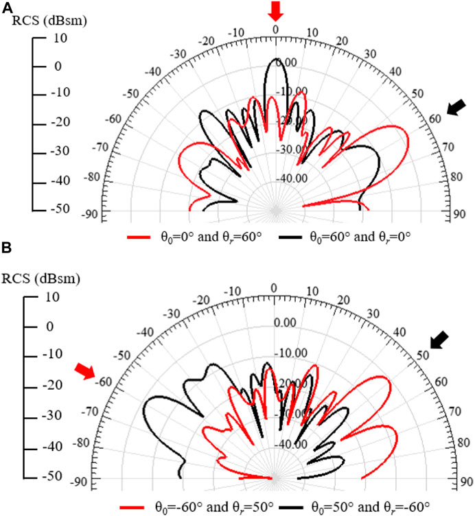
FIGURE 13. Simulated RIS angle reciprocity response. (A) Normal plane wave. (B) Oblique plane wave.
For a multi-beam response, as envisioned in Figure 5, the 32 × 32 RIS has been configured as four independent sectors with 16 × 16 elements. Each independent sector is responsible for steering the beam at the desired direction. As an example, the RIS response for four different beams named (−30°, 0°), (60°, 0°), (−30°, 90°), and (60°, 90°) is displayed in Figure 14. The multi-beam RCS patterns have lower peak values than the previous results due to the reduced RIS area, which also produces wide beamwidth responses. Additionally, the reduced RIS dimensions generate beam peak position shifting. For the ϕr = 0° plane, the obtained beam peaks are at −29° and 57°, whereas for the ϕr = 90° plane, they are at −31° and 52°. Therefore, the RCS levels for multi-beam response might increase, and the beam peak shifting may be reduced by increasing the RIS size. Lastly, as the proposed RIS is based on the reflectarray concept, it is possible to implement other multi-beam or shaped-beam synthesis techniques (Nayeri et al., 2012)- (Bucci et al., 1991).
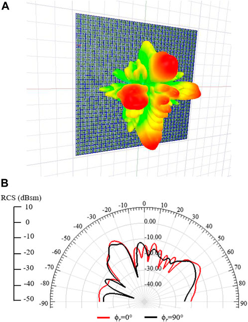
FIGURE 14. Simulated RIS multi-beam response. (A) 3-D RCS pattern. (B) 2-D RCS pattern.
Finally, Table 1 compares our proposed RIS and others in the literature. One may notice that most works were focused on the sub-6GHz band and 1-bit quantization phase. Also, it is shown that using PIN diodes provides lower reflection loss at the expense of lower quantization bit schemes, although complex architectures, as presented in (Rains et al., 2021) and (Dai et al., 2020), might be used to overcome this limitation. According to the desired application scenario, the RIS must operate at the far-field region with plane wave excitation similar to the works presented in (Rains et al., 2021), (Araghi et al., 2022), and (Liang et al.). Spherical wave excitation, as shown in (Trichopoulos et al., 2022), (Gros et al., 2021), (Pei et al., 2021), and (Dai et al., 2020), demands an antenna close to RIS to generate the spherical wave phase distribution, inconsistent with far-located source signals.
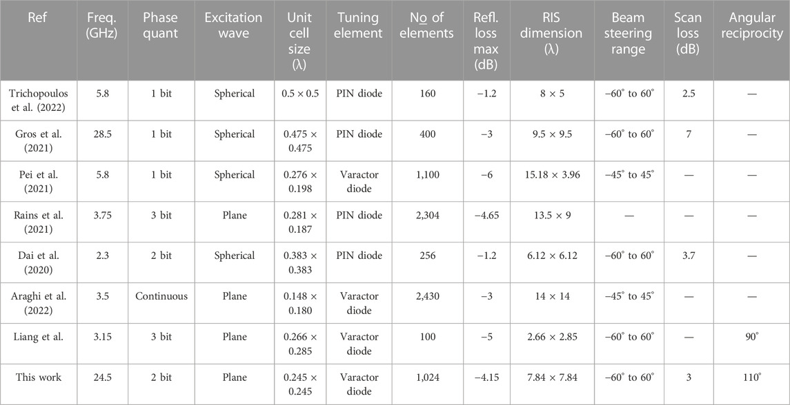
TABLE 1. Comparison of related works on RIS.
Regarding the coverage area, most RISs generate a 120° sector region commonly used in mobile applications, where the proposed design provides a reasonable scan loss of 3 dB. In summary, our proposed RIS operates in the mm-waves frequency band with small-size unit cells, improving overall performance besides using a 2-bit quantization phase. Moreover, considering the high operating frequency and tuning element losses, a reasonable maximum reflection loss has been achieved. Lastly, the designed RIS provides a 110° angular reciprocity, responsible for RIS oblique angles operating scenario.
3 RIS-aided wireless communication
RCS patterns have been commonly used to evaluate RIS response and reflectivity (Trichopoulos et al., 2022), (Araghi et al., 2022), (Wu et al., 2008), (Kashyap et al., 2020). Since RCS depends on the surface geometry and electrical properties, incident plane wave characteristics and operating frequency, it represents an alternative to numerically model and evaluate RISs, including system level performance analysis. Moreover, RIS can be viewed as a secondary radiation source applying its RCS results to ray-tracing analysis (Liu and Sarris, 2022). Applying the bistatic radar equation, the power relation by placing a RIS between a transmitter and receiver can be estimated as follows (Trichopoulos et al., 2022)
where Pt is the transmitted power; Pr is the received power; Gt and Gr are the transmitter and receiver gain, respectively; λ is the operation wavelength; σ is the RCS of the RIS; dt and dr are the distance between transmitter-RIS and receiver-RIS, respectively. The received and transmitted power relationship can be determined using the unit cell response, as applied in (Tang et al., 2021). Non-etheless, this approach does not consider the unit cell interactions as a whole surface.
Using the RIS results from Figure 12, the RCS curves were calculated for the normal incident plane wave (0°,0°) and reflected beams from −60° to 60° at ϕr = 0°. The RCS peak values as a function of the reflected angle are presented in Figure 15. Since the RCS values behave as a cosine function, according to the reflected angle, we have modeled the results in Figure 15 as follows
where θr is the reflected angle in degrees. The yellow dashed line curve in Figure 15 represents the results using Eq. 5 to model the RCS response for the proposed RIS. Applying an arbitrary angle to (5) makes it possible to determine RCS and, consequently, the relation between transmitted and received power according to (4).
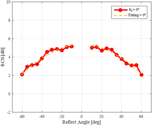
FIGURE 15. Simulated RIS RCS modeling.
For example, we have considered the following scenario: a transmitter-RIS distance of 60 m and a receiver-RIS distance of 15 m; height difference of 10 m and 3 m between transmitter-RIS and receiver-RIS, respectively; transmission power of 24 dBm; transmitter and receiver antenna gain of 20 dBi and 15 dBi, respectively. Finally, the achievable rate can be calculated by the Shannon formula, i.e.,
where
According to (6), we can calculate the achievable rate via the received power Pr, obtained via (4). Figure 16 reports the results for the elucidated example. From this result, it can be observed that the achievable rate shows a monotonically increasing trend with regard to the reflecting angle and then declines after the angle is greater than zero degrees. This result demonstrates that a symmetric function can represent the received power to produce the symmetric curve in terms of achievable rate. Additionally, it verifies the optimal achievable rate obtained at a certain angle of reflection.
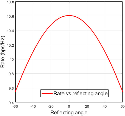
FIGURE 16. Achievable rate according to the reflecting angle.
Finally, the proposed RIS might be evaluated at a system level for performance analysis by implementing expressions similar to (5) for other incident and reflected angles. Given the proposed scenario, the achievable rate for θ0 = 0° and θr = 50° was 9.84 bps/Hz. However, by increasing the incident angle to θ0 = −60° and keeping the reflected angle θr = 50° (Figure 13A), the RCS peak level decreases to −0.63 dBsm. In this case, the achieved rate is reduced to 8.61 bps/Hz due to the increased incident wave angle.
4 Conclusion
We have reported a varactor-based 1024-element RIS design and its numerical system-level performance analysis using a RCS-based approach. The proposed RIS is based on a 2-bit unit cell loaded with varactor diodes, arranged in a 32 × 32 matrix operating at 24.5 GHz with incident plane waves. Our RIS is envisioned to be applied in mm-waves scenarios for coverage extension, mainly at the azimuth plane. We have demonstrated a beam steering from −60° to 60° in the azimuth plane with roughly 3 dB scan loss at each direction. In addition, an angle reciprocity analysis has been conducted to validate the proposed RIS operation at both orientation angles. As a result, angular reciprocity for 110°, even under an oblique incident wave in both directions, has been demonstrated. To the best of our knowledge, this is the highest RIS angular reciprocity reported in the literature. Future works include the beam steering analysis in the elevation plane to extract RCS curves, with the purpose of performing new system-level performance evaluations. Lastly, we plan to fabricate a RIS prototype and test it in a real 5G NR system.
Data availability statement
The original contributions presented in the study are included in the article/supplementary material, further inquiries can be directed to the corresponding author.
Author contributions
All authors listed have made a substantial, direct, and intellectual contribution to the work and approved it for publication.
Funding
This work was partially supported by RNP, with resources from MCTIC, Grant No. 01245.020548/2021-07, under the 6G Mobile Communications Systems project of the Radiocommunication Reference Center (Centro de Referência em Radiocomunicações—CRR) of the National Institute of Telecommunications (Instituto Nacional de Telecomunicações—Inatel), Brazil.
Acknowledgments
The authors also thank the financial support from CNPq, CAPES, FINEP and FAPEMIG.
Conflict of interest
The authors declare that the research was conducted in the absence of any commercial or financial relationships that could be construed as a potential conflict of interest.
Publisher’s note
All claims expressed in this article are solely those of the authors and do not necessarily represent those of their affiliated organizations, or those of the publisher, the editors and the reviewers. Any product that may be evaluated in this article, or claim that may be made by its manufacturer, is not guaranteed or endorsed by the publisher.
References
3GPP, 5G, and, NR. User Equipment (UE) radio transmission and reception; Part 2: Range 2 Standalone,” 3GPP TS 38.101-2 version 15.2. 0 Release 15, 2018–2107.
Abadal, S., Cui, T. -J., Low, T., and Georgiou, J. (2020). Programmable metamaterials for software-defined electromagnetic control: Circuits, systems, and architectures. IEEE J. Emerg. Sel. Top. Circuits Syst. 10 (1), 6–19. doi:10.1109/jetcas.2020.2976165
Reconfigurable intelligent surfaces standardization (2022). Jun. 2022. [Online] Available: https://www.etsi.org/technologies/reconfigurable-intelligent-surfaces.
Araghi, A., Khalily, M., Safaei, M., Bagheri, A., Singh, V., Wang, F., et al. (2022). Reconfigurable intelligent surface (RIS) in the sub-6 GHz band: Design, implementation, and real-world demonstration. IEEE Access 10, 2646–2655. doi:10.1109/access.2022.3140278
Bai, T., Pan, C., Han, C., and Hanzo, L. (2021). Empowering mobile edge computing by exploiting reconfigurable intelligent surface. [Online]. Available: https://arxiv.org/abs/2102.02569.
Bariah, L., Mohjazi, L., Muhaidat, S., Sofotasios, P. S., Kurt, G. K., Yanikomeroglu, H., et al. (2020). A prospective look: Key enabling technologies, applications and open research topics in 6G networks. IEEE Access 8, 174792–174820. doi:10.1109/access.2020.3019590
Basar, E., Di Renzo, M., De Rosny, J., Debbah, M., Alouini, M. -S., and Zhang, R. (2019). Wireless communications through reconfigurable intelligent surfaces. IEEE Access 7, 116753–116773. doi:10.1109/access.2019.2935192
Basar, E., Yildirim, I., and Kilinc, F. (2021). Indoor and outdoor physical channel modeling and efficient positioning for reconfigurable intelligent surfaces in mmWave bands. IEEE Trans. Commun. 69 (12), 8600–8611. doi:10.1109/tcomm.2021.3113954
Biswas, S. R., Gutierrez, C. E., Nemilentsau, A., Lee, I. H., Oh, S. H., Avouris, P., et al. (2018). Tunable graphene metasurface reflectarray for cloaking, illusion, and focusing," in Phys. Rev. Appl., vol. 9, no. 034021, doi:10.1103/physrevapplied.9.034021
Björnson, E., and Sanguinetti, L. (2020). Power scaling laws and near-field behaviors of massive MIMO and intelligent reflecting surfaces. IEEE Open J. Commun. Soc. 1, 1306–1324. doi:10.1109/ojcoms.2020.3020925
Bucci, O. M., Mazzarella, G., and Panariello, G. (1991). Reconfigurable arrays by phase-only control. IEEE Trans. Antennas Propag. 39 (7), 919–925. doi:10.1109/8.86910
Chen, H. T., Taylor, A. J., and Yu, N. (2016). A review of metasurfaces: Physics and applications. Rep. Prog. Phys. 79 (7), 076401. Art. no. doi:10.1088/0034-4885/79/7/076401
Chen, W., Bai, L., Tang, W., Jin, S., Jiang, W. X., and Cui, T. J. (2020). Angle-dependent phase shifter model for reconfigurable intelligent surfaces: Does the angle-reciprocity hold? IEEE Commun. Lett. 24 (9), 2060–2064. doi:10.1109/lcomm.2020.2993961
Chu, Z., Hao, W., Xiao, P., and Shi, J. (2020). Intelligent reflecting surface aided multi-antenna secure transmission. IEEE Wirel. Commun. Lett. 9 (1), 108–112. doi:10.1109/lwc.2019.2943559
Cui, T. J., Smith, D., and Liu, R. (2009). Metamaterials: Theory, design, and applications. Springer.
da Silva, L. G., and Xiao, P. (2022). A 2-bit tunable unit cell for 6G reconfigurable intelligent surface application. Madrid, Spain: 16th European Conference on Antennas and Propagation (EuCAP).
da Silva, L. G., and Arismar Cerqueira, S., (2021). "Wide incident angle digital coding metasurface applied to reconfigurable intelligent surfaces," Antenna Measurement Techniques Association Symposium (AMTA).
Dai, L., Wang, B., Wang, M., Yang, X., Tan, J., Bi, S., et al. (2020). Reconfigurable intelligent surface-based wireless communications: Antenna design, prototyping, and experimental results. IEEE Access 8, 45913–45923. doi:10.1109/access.2020.2977772
Di Renzo, M., Debbah, M., Phan-Huy, D. T., Zappone, A., Alouini, M. S., Yuen, C., et al. (2019). Smart radio environments empowered by reconfigurable AI meta-surfaces: An idea whose time has come. EURASIP J. Wirel. Commun. Netw. 2019, 129. article 129. doi:10.1186/s13638-019-1438-9
Di Renzo, M., Ntontin, K., Song, J., Danufane, F. H., Qian, X., Lazarakis, F., et al. (2020). Reconfigurable intelligent surfaces vs. Relaying: Differences, similarities, and performance Comparison. IEEE Open J. Commun. Soc. 1, 798–807. doi:10.1109/ojcoms.2020.3002955
Di Renzo, M., Zappone, A., Debbah, M., Alouini, M. S., Yuen, C., de Rosny, J., et al. (2020). Smart radio environments empowered by reconfigurable intelligent surfaces: How it works, state of research, and the road ahead. IEEE J. Sel. Areas Commun. 38 (11), 2450–2525, Nov. doi:10.1109/jsac.2020.3007211
Díaz-Rubio, A., Asadchy, V. S., Elsakka, A., and Tretyakov, S. A. (2017). From the generalized reflection law to the realization of perfect anomalous reflectors. Sci. Adv. 3 (8), e1602714. doi:10.1126/sciadv.1602714
Foo, S. (2017). “Liquid-crystal reconfigurable metasurface reflectors,” in Proc. IEEE int. Symp. Antennas propag. USNC/URSI nat (San Diego, CA, USA: Radio Sci. Meeting), 2069–2070.
Gacanin, H., and Di Renzo, M. (2020). Wireless 2.0: Toward an intelligent radio environment empowered by reconfigurable meta-surfaces and artificial intelligence. IEEE Veh. Technol. Mag. 15 (4), 74–82. doi:10.1109/mvt.2020.3017927
Glybovski, S. B., Tretyakov, S. A., Belov, P. A., Kivshar, Y. S., and Simovski, C. R. (2016). Metasurfaces: From microwaves to visible. Phys. Rep. 634, 1–72. doi:10.1016/j.physrep.2016.04.004
Gong, S., Lu, X., Hoang, D. T., Niyato, D., Shu, L., Kim, D. I., et al. (2020). Toward smart wireless communications via intelligent reflecting surfaces: A contemporary survey. IEEE Commun. Surv. Tutorials 22 (4), 2283–2314. doi:10.1109/comst.2020.3004197
Gros, J. -B., Popov, V., Odit, M. A., Lenets, V., and Lerosey, G. (2021). A reconfigurable intelligent surface at mmWave based on a binary phase tunable metasurface. IEEE Open J. Commun. Soc. 2, 1055–1064. doi:10.1109/ojcoms.2021.3076271
He, J., Wymeersch, H., Kong, L., Silvén, O., and Juntti, M. (2020). Large intelligent surface for positioning in millimeter wave MIMO systems. IEEE 91st Vehicular Technology Conference (VTC2020-Spring).
He, S., Yang, H., Jiang, Y., Deng, W., and Zhu, W. (2019). Recent advances in MEMS metasurfaces and their applications on tunable lens. Micromachines 10 (8), 505. doi:10.3390/mi10080505
Holloway, C. L., Mohamed, M. A., Kuester, E. F., and Dienstfrey, A. (2005). Reflection and transmission properties of a metafilm: With an application to a controllable surface composed of resonant particles. IEEE Trans. Electromagn. Compat. 47 (4), 853–865. doi:10.1109/temc.2005.853719
Hong, W., Jiang, Z. H., Yu, C., Hou, D., Wang, H., Guo, C., et al. (2021). The role of millimeter-wave technologies in 5G/6G wireless communications. IEEE J. Microwaves 1 (1), 101–122. doi:10.1109/jmw.2020.3035541
Huang, C., Hu, S., Alexandropoulos, G. C., Zappone, A., Yuen, C., Zhang, R., et al. (2020). Holographic MIMO surfaces for 6G wireless networks: Opportunities, challenges, and trends. IEEE Wirel. Commun. 27 (5), 118–125. doi:10.1109/mwc.001.1900534
Islam, N. A., and Choi, S. (2020). Compact folded dipole metasurface for high anomalous reflection angles with low harmonic levels. Sci. Rep. 10 (1), 18125–18213. doi:10.1038/s41598-020-75230-2
Kashyap, B. G., Theofanopoulos, P. C., Cui, Y., and Trichopoulos, G. C. (2020). Mitigating quantization lobes in mmWave low-bit reconfigurable reflective surfaces. IEEE Open J. Antennas Propag. 1, 604–614. doi:10.1109/ojap.2020.3034049
Kitayama, D., Hama, Y., Goto, K., Miyachi, K., Motegi, T., and Kagaya, O. (2021). Transparent dynamic metasurface for a visually unaffected reconfigurable intelligent surface: Controlling transmission/reflection and making a window into an RF lens. Opt. Express 29, 29292–29307. doi:10.1364/oe.435648
Kuester, E. F., Mohamed, M. A., Piket-May, M., and Holloway, C. L. (2003). Averaged transition conditions for electromagnetic fields at a metafilm. IEEE Trans. Antennas Propag. 51 (10), 2641–2651. doi:10.1109/tap.2003.817560
Li, L., Qiang, C., Qiaowei, Y., Sawaya, K., Maruyama, T., Furuno, T., et al. (2009). Novel broadband planar reflectarray with parasitic dipoles for wireless communication applications. IEEE Antennas Wirel. Propag. Lett. 8, 881–885. doi:10.1109/lawp.2009.2028298
Liang, J. C., et al. “An angle-insensitive 3-bit reconfigurable intelligent surface,” in IEEE Transactions on Antennas and propagation, early access.
Liang, Y., Long, R., Zhang, Q., Chen, J., Cheng, H. V., and Guo, H. (2019). Large intelligent surface/antennas (LISA): Making reflective radios smart. J. Commun. Inf. Netw. 4 (2), 40–50. doi:10.23919/jcin.2019.8917871
Liaskos, C., Nie, S., Tsioliaridou, A., Pitsillides, A., Ioannidis, S., and Akyildiz, I. (2018). A new wireless communication paradigm through software-controlled metasurfaces. IEEE Commun. Mag. 56 (9), 162–169. doi:10.1109/mcom.2018.1700659
Lin, S., Zheng, B., Alexandropoulos, G. C., Wen, M., Renzo, M. D., and Chen, F. (2021). Reconfigurable intelligent surfaces with reflection pattern modulation: Beamforming design and performance analysis. IEEE Trans. Wirel. Commun. 20 (2), 741–754. doi:10.1109/twc.2020.3028198
Liu, Y., and Sarris, C. (2022). Efficient propagation modeling for communication channels with reconfigurable intelligent surfaces. [Online]. Available. doi:10.36227/techrxiv.19433765.v2
Nayeri, P., Yang, F., and Elsherbeni, A. Z. (2012). Design and experiment of a single-feed quad-beam reflectarray antenna. IEEE Trans. Antennas Propag. 60 (2), 1166–1171. doi:10.1109/tap.2011.2173126
Nayeri, P., Yang, F., and Elsherbeni, A. Z. (2018). Reflectarray antennas: Theory, designs, and applications. Hoboken, NJ, USA: Wiley.
Nemati, M., Park, J., and Choi, J. (2020). RIS-assisted coverage enhancement in millimeter-wave cellular networks. IEEE Access 8, 188171–188185. doi:10.1109/access.2020.3031392
Sydoruk, O., Tatartschuk, E., Shamonina, E., and Solymar, L., (2009). "Analytical formulation for the resonant frequency of split rings," in J. Appl. Phys., vol. 105, no. 1, pp. 1–5. doi:10.1063/1.3056052-4
Özdogan, Ö., Björnson, E., and Larsson, E. G. (2020). Using intelligent reflecting surfaces for rank improvement in MIMO communications. ICASSP 2020 - 2020 IEEE International Conference on Acoustics, Speech and Signal Processing. (ICASSP).
Pan, C., Ren, H., Wang, K., Kolb, J. F., Elkashlan, M., Chen, M., et al. (2021). Reconfigurable intelligent surfaces for 6G systems: Principles, applications, and research directions. IEEE Commun. Mag. 59 (6), 14–20. doi:10.1109/mcom.001.2001076
Pei, X., Yin, H., Tan, L., Cao, L., Li, Z., Wang, K., et al. (2021). RIS-aided wireless communications: Prototyping, adaptive beamforming, and indoor/outdoor field trials. IEEE Trans. Commun. 69 (12), 8627–8640. doi:10.1109/tcomm.2021.3116151
Perović, N. S., Renzo, M. D., and Flanagan, M. F. (2020). channel capacity optimization using reconfigurable intelligent surfaces in indoor mmWave environments. ICC 2020 - 2020 IEEE International Conference on Communications (ICC).
Pitilakis, A., Tsilipakos, O., Liu, F., Kossifos, K. M., Tasolamprou, A. C., Kwon, D. H., et al. (2021). A multi-functional reconfigurable metasurface: Electromagnetic design accounting for fabrication aspects. IEEE Trans. Antennas Propag. 69 (3), 1440–1454. doi:10.1109/tap.2020.3016479
Rains, J., et al. (2021). High-resolution programmable scattering for wireless coverage enhancement: An indoor field trial campaign. [Online]. Available: https://arxiv.org/abs/2112.11194.
Rappaport, T. S., Xing, Y., MacCartney, G. R., Molisch, A. F., Mellios, E., and Zhang, J. (2017). Overview of millimeter wave communications for fifth-generation (5G) wireless networks—with a focus on propagation models. IEEE Trans. Antennas Propag. 65 (12), 6213–6230. doi:10.1109/tap.2017.2734243
Shojaeifard, A., Wong, K.-K., Tong, K.-F., Chu, Z., Mourad, A., Haghighat, A., et al. (2022). MIMO evolution beyond 5G through reconfigurable intelligent surfaces and fluid antenna systemsProceedings of the IEEE 110 (9), 1244–1265. doi:10.1109/JPROC.2022.3170247
Subrt, L., Grace, D., and Pechac, P. (2010). Controlling the short-range propagation environment using active frequency selective surfaces. Radioengineering 19 (4), 610–615.
Tan, X., Sun, Z., Koutsonikolas, D., and Jornet, J. M. (2018). Enabling indoor mobile millimeter-wave networks based on smart reflect-arrays. IEEE INFOCOM 2018 - IEEE Conference on Computer Communications, 270–278.
Tang, W., Chen, M. Z., Chen, X., Dai, J. Y., Han, Y., Di Renzo, M., et al. (2021). Wireless communications with reconfigurable intelligent surface: Path loss modeling and experimental measurement. IEEE Trans. Wirel. Commun. 20 (1), 421–439. doi:10.1109/twc.2020.3024887
Trichopoulos, G. C., Theofanopoulos, P., Kashyap, B., Shekhawat, A., Modi, A., Osman, T., et al. (2022). Design and evaluation of reconfigurable intelligent surfaces in real-world environment. IEEE Open J. Commun. Soc. 3, 462–474. doi:10.1109/ojcoms.2022.3158310
Wan, Z., Gao, Z., Gao, F., Renzo, M. D., and Alouini, M. -S. (2021). Terahertz massive MIMO with holographic reconfigurable intelligent surfaces. IEEE Trans. Commun. 69 (7), 4732–4750. doi:10.1109/tcomm.2021.3064949
Wang, P., Fang, J., Yuan, X., Chen, Z., and Li, H. (2020). Intelligent reflecting surface-assisted millimeter wave communications: Joint active and passive precoding design. IEEE Trans. Veh. Technol. 69 (12), 14960–14973. doi:10.1109/tvt.2020.3031657
Wu, B., Sutinjo, A., Potter, M. E., and Okoniewski, M. (2008). On the selection of the number of bits to control a dynamic digital MEMS reflectarray. IEEE Antennas Wirel. Propag. Lett. 7, 183–186. doi:10.1109/lawp.2008.920908
Wu, Q., and Zhang, R. (2020). Towards smart and reconfigurable environment: Intelligent reflecting surface aided wireless network. IEEE Commun. Mag. 58 (1), 106–112. doi:10.1109/mcom.001.1900107
Wu, Q., Zhang, S., Zheng, B., You, C., and Zhang, R. (2021). Intelligent reflecting surface aided wireless communications: A tutorial. IEEE Trans. Commun. 69 (5), 3313–3351. doi:10.1109/tcomm.2021.3051897
Yang, H., Yang, F., Xu, S., Li, M., Cao, X., Gao, J., et al. (2017). A study of phase quantization effects for reconfigurable reflectarray antennas. IEEE Antennas Wirel. Propag. Lett. 16, 302–305. doi:10.1109/lawp.2016.2574118
Yin, J., Wu, Q., Lou, Q., Wang, H., Chen, Z. N., and Hong, W. (2020). Single-beam 1 bit reflective metasurface using prephased unit cells for normally incident plane waves. IEEE Trans. Antennas Propag. 68 (7), 5496–5504. doi:10.1109/tap.2020.2978285
Keywords: 6G, B5G, beamforming, beam steering, metamaterial, reconfigurable intelligent surface, reflectarray
Citation: da Silva LG, Chu Z, Xiao P and Cerqueira S A (2023) A varactor-based 1024-element RIS design for mm-waves. Front. Comms. Net 4:1086011. doi: 10.3389/frcmn.2023.1086011
Received: 31 October 2022; Accepted: 09 March 2023;
Published: 22 March 2023.
Edited by:
Wei Liang, Northwestern Polytechnical University, ChinaReviewed by:
Suresh Venkatesh, Princeton University, United StatesCan Wu, Stanford University, United States
Copyright © 2023 da Silva, Chu, Xiao and Cerqueira S. This is an open-access article distributed under the terms of the Creative Commons Attribution License (CC BY). The use, distribution or reproduction in other forums is permitted, provided the original author(s) and the copyright owner(s) are credited and that the original publication in this journal is cited, in accordance with accepted academic practice. No use, distribution or reproduction is permitted which does not comply with these terms.
*Correspondence: Pei Xiao, p.xiao@surrey.ac.uk