Modeling pore wetting in direct contact membrane distillation—effect of interfacial capillary pressure
 S. N. A. Ahmad1 Takeshi Matsuura1,2
  Juhana Jaafar1*
  L. Y. Jiang3
  A. F. Ismail1
  M. H. D. Othman1 Mukhlis A. Rahman1
- 1Advanced Membrane Technology Research Centre (AMTEC), Faculty of Chemical and Energy Engineering, Universiti Teknologi Malaysia, Johor Bahru, Johor, Malaysia
- 2Department of Chemical and Biological Engineering, University of Ottawa, Ottawa, ON, Canada
- 3School of Metallurgy and Environment, Central South University, Changsha, Hunan, China
In this study, we aimed to develop a model for computing direct contact membrane distillation (DCMD) performance, taking into account capillary pressure effects at the liquid–gas interface within membrane pores. We developed a simulation model to investigate how factors such as pore radius, feed/permeate temperature, pressure, and contact angle influenced the distance of liquid intrusion into the pore, the weight flow rate in a single pore, and the temperature at the liquid–gas interface. The model predicted that the permeation rate would decrease with an increase in the feed pressure when the permeate pressure was kept constant and also when the pressure difference between the feed and permeate was kept constant. It also predicted that the permeation rate would increase with an increase in the permeate pressure when the feed pressure was kept constant. The model also indicated that partial pore wetting would be enhanced with an increase in feed pressure when the pore size was as large as 1 μm but would diminish when the pore size was as small as 0.1 μm. According to the model, partial pore wetting diminished with a decrease in the permeate pressure. The model’s predictions were in line with the trends observed in the experimental DCMD flux data by many authors, particularly those regarding the effects of feed and permeate temperature and the effect of contact angle. The model’s predictions were compared with the experimental data recorded in the literature, validating the model’s accuracy.
1 Introduction
Membrane distillation (MD) is a thermally driven separation process utilizing microporous membranes and operating on the principle of liquid–vapor equilibrium. In this process, only the volatile component (typically water) of the feed solution evaporates at the pore inlet, transfers through the pore, and exits from the pore outlet in either vapor or condensed form. The membrane material must be hydrophobic to prevent liquid water from entering the pore.
MD finds applications in the desalination of seawater and brackish water and treating concentrated brine from the reverse osmosis (RO) process (Rácz et al., 2014; Ibrar et al., 2022). Despite its impressive performance, commercialization faces challenges due to pore wetting, causing a significant decrease in MD flux and selectivity (Peña et al., 1993; Alklaibi and Lior, 2005; Gryta, 2005; 2007; Karakulski and Gryta, 2005; Peng et al., 2005; Tun et al., 2005; He et al., 2008; Qtaishat et al., 2009; Pangarkar et al., 2011; Camacho et al., 2013; Guillen-Burrieza et al., 2013; Peng et al., 2013; Saffarini et al., 2013; Rezaei and Samhaber, 2016).
Efforts have been made to mitigate MD pore wetting, including methods like liquid entry pressure (LEP) evaluation, introducing air bubbles into the feed solution, and dewetting the pores for regeneration and reuse (Baghbanzadeh et al., 2016; Warsinger et al., 2017; Ibrar et al., 2022; Hou et al., 2023). One of the most useful methods to evaluate the membrane’s resistance against pore wetting is LEP, which is related to the contact angle and pore geometry (Rácz et al., 2014; Yazgan-Birgi et al., 2018). New devices have been designed and constructed to introduce air bubbles into the feed solution (Rezaei et al., 2018), and the pores have been dewetted to regenerate and reuse the membrane (Shin et al., 2016; Warsinger et al., 2017).
The principle of LEP is based on the following Laplace equation:
where
The contact angle in MD is integral to understanding surface properties and wetting behavior and is closely linked to thermodynamics. Surface energy, a key thermodynamic concept, delineates the energy at interfaces between phases. In MD, the contact angle, a representation of equilibrium between cohesive and adhesive forces, is mathematically expressed by the Young–Laplace equation, connecting the contact angle (θ) with surface tensions (γSL, γSG, and γLG). Hydrophobic behavior, characterized by contact angles exceeding 90°, implies reduced wetting, while contact angles below 90° indicate hydrophilic behavior, signaling increased wetting. This alignment with thermodynamics underscores the tendency of systems to seek lower energy states. Hydrophobic surfaces minimize solid–liquid interfacial energy, while hydrophilic surfaces minimize liquid–gas interfacial energy. In DCMD, thermodynamics governs the vapor–liquid equilibrium. The contact angle influences membrane surface wetting, impacting mass transfer and overall MD performance. Designing and optimizing MD systems for efficiency hinges on thermodynamic principles.
Consideration of small capillaries introduces confinement effects that alter water behavior. While thermodynamics still governs wetting, capillary size, roughness, and confinement modify equilibrium conditions. The meniscus formed in capillaries may deviate from the flat surface scenario due to these effects. The Young–Laplace equation (ΔP =
In DCMD, a capillary is in contact with the feed and permeate water stream at the pore entrance and exit, respectively, and gas is trapped in between. When a capillary made of hydrophobic material is placed between two water phases, both at room temperature (see Figure 1A), the meniscus formed at the pore entrance is convex rightward, and the meniscus at the pore exit is convex leftward (Ashoor et al., 2016). The liquid phase pressure is slightly higher than the gas phase pressure to counterbalance the capillary pressure. If the temperature of the feed water is gradually increased, the gas phase pressure near the pore entrance will increase due to the evaporation of water, and it may surpass that of the liquid pressure when the feed water temperature is high enough. Then, in order to counterbalance the pressure difference, the meniscus at the pore entrance should change to concave leftward (Figure 1B); otherwise, the gas would appear in the feed water as gas bubbles. Thus, it is possible for the meniscus to change from the convex right (Figure 1A) to the concave left (Figure 1B), particularly at the pore entrance (Biswas and Kartha, 2019). This effect is negligible at the pore exit because the permeate stream is maintained at room temperature.
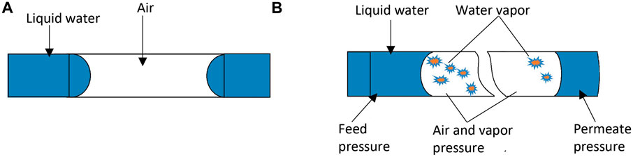
Figure 1. Meniscus change under high-pressure in the trapped air. (A) Pore entrance: convex right; exit: convex left. (B) Entrance shifts to concave left; exit to concave right.
Based on this conceptual experiment, the discussions in this work use contact angles below 90o in the pore, in most cases, which allows drawing water into the capillary pore at the feed side of the pore, even when the pore is made of hydrophobic material.
Indeed, Gryta (2007) reported the possibility of partial pore wetting based on experiments conducted using hydrophobic MD membranes. Gryta’s comprehensive investigation identified a spectrum of pore-wetting phenomena encompassing four distinct categories:
1) Non-wetted: The entire membrane pore is filled with gas/vapor.
2) Surface-wetted: The pore is partially filled with liquid. A gas/vapor layer remains between the liquid layers at the entrance and exit of the pore.
3) Partial-wetted: As pore wetting proceeds, some pores are completely filled with liquid.
4) Wetted: The pore is completely filled with liquid, and the feed solution leaks to the permeate.
Confirmation of the concept of partial pore wetting is supported by Gryta’s work, where SEM/EDX analysis revealed concentration profiles of magnesium and calcium within the membrane pore (Gryta, 2007). Zhu et al. (2015) also observed the partial pore wetting of the PVA/PVDF composite hollow fiber membrane used for DCMD by applying SEM/EDX.
In wetting experiments involving PVDF, understanding channel geometry is paramount for grasping the interaction dynamics between liquids and PVDF membranes, as well as the influence of different geometrical features on wetting behavior. Research on PVDF hollow fiber membranes immersed in various solutions has yielded valuable insights into wetting behavior (Ritter, 2022). Moreover, investigations into the impact of channel wettability and geometry on water plug wetting underscore the importance of these factors in wetting phenomena (Pfeiffer et al., 2017). Consequently, examining the channel geometry of PVDF in wetting experiments becomes crucial for comprehending liquid–membrane interactions, understanding the influence of geometrical features on wetting behavior, and discerning how membrane properties are influenced by channel geometry.
Parameter screening studies on PVDF/PVP multi-channel capillary membranes further highlight the significance of channel geometry in shaping membrane properties and performance. Essential factors such as PVDF content, PVP molecular weight, pore size, and surface roughness play pivotal roles in determining membrane characteristics and behavior in wetting experiments (Back et al., 2019). In summary, when discussing wetting phenomena, it is imperative to consider parameters such as feed salinity, feed cross velocity, and channel geometry, as they significantly impact how liquids spread on a solid substrate. It is essential to note, however, that this particular study introduces an assumption regarding the simplification of pores as simple cylindrical channels. This simplification mirrors a similar geometric representation observed in previous studies, ensuring consistency and comparability in the analytical approach.
Jacob et al. (2018) made a very detailed study of pore wetting of vacuum membrane distillation (VMD), also using SEM/EDX, and proposed two pore wetting indicators: 1) the proportion of totally wetted membrane area (ωs) and 2) the average rate of liquid intrusion in the pore (called pore wetting) (ωp). Eljaddi and Cabassud (2022) applied the same method to a photoplasmonic PVDF membrane, incorporating Ag-nanoparticles, and unveiled that the integration of Ag-nanoparticles enhances partial pore wetting.
Typically, the occurrence of pore wetting in hydrophobic membranes is attributed to the hydrophilization of the pore entrance. This transformation is often triggered by the deposition of salt crystals or hydrophilic foulants, alongside the conversion of a hydrophobic material to a hydrophilic state through various chemical reactions. This rationale further supports the assumption of a contact angle of less than 90° in the model prediction. However, despite the widespread acceptance of these mechanisms, a comprehensive interpretation of pore wetting based on mass and heat transport remains elusive.
Notably, the groundbreaking work by Chamani et al. (2019) on vacuum membrane distillation (VMD) provides a remarkable exception. Their research delves into the intricacies of pore wetting with a distinct focus on mass and heat transport dynamics. This stands in stark contrast to the prevailing trends in the advancement of membrane materials, fabrication methods, and characterization techniques for MD. Chamani et al.'s findings underscore the need for a nuanced understanding of pore-wetting mechanisms, challenging conventional perspectives and stimulating further exploration in this crucial aspect of membrane science and technology.
The objective of this work is to present a model for DCMD transport in which simultaneous mass and heat transfer is considered, particularly under the influence of the capillary pressure at the liquid–gas interface. Using the model, the effects of pore radius, contact angle in the pore, feed and permeate pressure on the length of water uptake in the pore, the temperature at the water–gas interface, and the MD flux are studied. The results obtained by the model simulation are further compared with the trends observed by the experimental data and reported in the literature.
2 Theory
The following assumptions are made to simplify the model:
• The feed contains only water. Hence, in the model development, liquid means water.
• The pore is straight and cylindrical.
• The thermal conductivity of the membrane material is so low that only the heat transfer in the pore is considered. This assumption and the following two assumptions are made to examine purely the effects of mass and heat transfer occurring in the pore on the MD mass flux without the effects of other factors.
• The heat enters into the water inside the pore only from the pore entrance. The heat does not enter from the pore wall.
• Boundary layer resistance of the feed liquid is ignored.
• The liquid mass transfer inside the pore follows the Poiseuille flow.
• The vapor mass transfer inside the pore follows the combined Knudsen/molecular diffusion mechanism.
• The meniscus of the liquid–vapor interface does not affect saturation vapor pressure.
• Heat transfer in the longitudinal direction is dominant.
• The liquid is incompressible
2.1 Mass transfer
The MD transport model in a single pore is developed for the steady state at which the liquid–vapor phase boundary remains inside the pore (Figure 2).
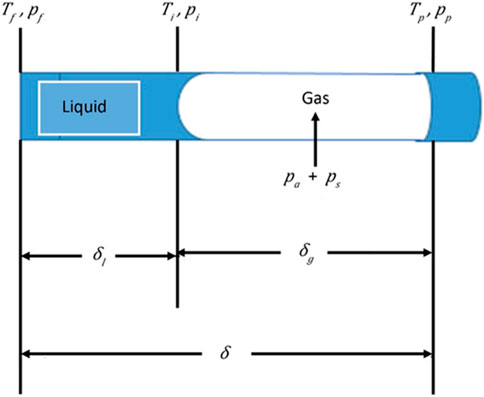
Figure 2. Transport behavior model in DCMD.
In DCMD, both ends of the pore are in contact with liquid, and it seems possible that liquid enters from both sides. However, for the reason given in the introduction, it is assumed that the liquid enters only from the pore entrance that is in contact with the feed stream.
There is some evidence to support the water entry from the feed side. For example, Gryta (2007) reported that water partially filled the pore from the feed side to the distance of 15 µm in the total 400 µm of membrane thickness by showing the Mg and Ca content profile in the longitudinal direction of the pore by EDX, wherein DCMD was performed by polypropylene membrane using tap water as a feed. Jiang and co-workers also showed the presence of Na on the feed side by EDX when DCMD was performed by their hydrophilic–hydrophobic hybrid membrane (Zhu et al., 2015; Feng et al., 2017). Based on this assumption, the model is also applicable for air gap membrane distillation (AGMD) with some changes in the transport parameters.
2.1.1 Liquid transport
For the liquid phase
where
where
where
In the above equations, the temperature dependence of the liquid properties is considered. Thus,
where
2.1.2 Transport in the gas phase
In this work, the membrane pore sizes in a range of 0.01–1 × 10⁻⁶ m are considered for DCMD. Because the mean free path of water at an atmospheric pressure and 50°C is 0.14 × 10⁻⁶ m (Khayet and Matsuura, 2011), the Knudsen numbers for such pores are 0.07–7.1. Hence, the combined Knudsen/ordinary diffusion mechanism is used for the transport of water vapor in air that is trapped between two liquid phases.
Then,
where
The following equations are used in Eq. 7:
where
where
where
As for the diffusivity of water vapor in air D (m2/s),
where Datm is the diffusivity (m2/s) at an atmospheric pressure, which is calculated by Bolz (1973):
Furthermore,
where N is the mass flux of water (kg/s) through the liquid and gas phases.
As for the saturation vapor pressure of water,
are used at the liquid–gas interface and at the pore exit, respectively.
2.2 Heat transfer
For the heat transfer in the liquid phase, the following differential equation is used at the steady state:
where
where
The general solution of the differential equation is
where
Using the boundary conditions
where
where
Furthermore, because
In Eq. 25, the temperature dependence of
where
The simulation was performed using Microsoft Excel, and the algorithm is presented in Figure 3.
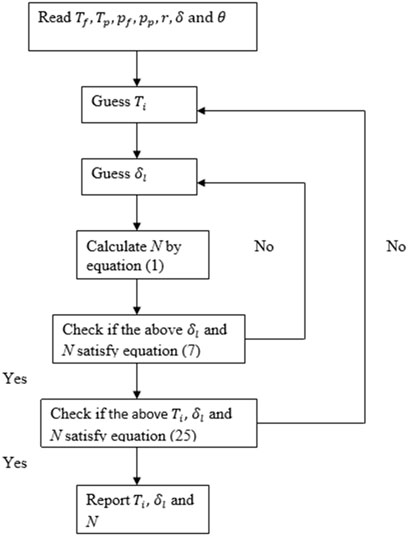
Figure 3. Simulation algorithm for DCMD transport.
3 Results and discussion
In addition to the temperature-dependent properties of water, as shown in Eqs. (4)–(6), the following parameters were used in the simulation; that is,
The heat transfer was calculated using Eqs. 18 through 27. Specifically, the heat transfer coefficient,
3.1 Effect of r
Figure 4 illustrates how varying the pore radius (r) affects
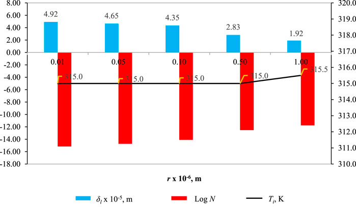
Figure 4. Effect of r on
In Figure 4, the influence of pore radius (r) on wetting characteristics, when the pore radius r = 0.01 × 10⁻⁶ m,
3.2 Effect of Tf
Figure 5 illustrates the impact of feed temperature Tf on
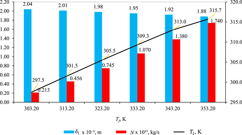
Figure 5. Effect of Tf on
In Figure 5, the effect of the impact of feed temperature (Tf) on wetting characteristics (blue bar),
3.3 Effect of Tp
Figure 6 shows the effect of Tp on
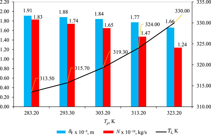
Figure 6. Effect of Tp on
As depicted in Figure 6, the liquid intrusion length
Temperature polarization (Tp): Tp represents the difference between the bulk feed temperature Tf and the temperature at the membrane/solution interface Tmf where the vapor–liquid transition occurs. As Tp increases, the temperature polarization,
Impact on mass flux (N): although temperature polarization decreases, there is also a decrease in mass flux (N) with increasing Tp. However, it is essential to recognize that the impact of Tp on mass flux is quantitatively smaller than the influence of feed temperature
The discrepancy between the effects of Tp and
3.4 Effect of pf
Figure 7 shows the effect of pf on
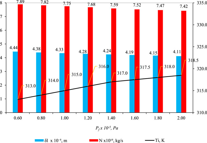
Figure 7. Effect of pf on
In Figure 7, a compelling pattern emerges: the parameter δl displays a decreasing trend as feed pressure (pf) increases. This seemingly paradoxical observation results from various factors. Despite higher feed pressure propelling liquid deeper into the pore, a simultaneous rise in temperature at the liquid–gas interface (Ti) amplifies capillary pressure in the gas phase (pg), diverting the liquid back toward the pore entrance. The findings in Figure 7 (blue bar) underscore that the influence of pg on δl outweighs that of pf. This pattern is also evident in the reduction of another parameter, N (mass flux of water through liquid and gas phases), as pf increases (Figure 7, red bar).
The initially counterintuitive decrease in δl with increasing pf becomes clear upon examining the role of capillary pressure (pg). As pf rises, more liquid infiltrates the pore structure, but the pivotal factor is the impact of pg, controlled by Ti. Analyzing the relationship between Ti, we observe its increase with pf, leading to an elevated saturation vapor pressure (ψpsi) (Eq. 16), subsequently influencing pg (Eq. 10). The essence lies in the dominance of pg over pf in influencing δl. Essentially, capillary forces play a predominant role in determining δl, and a similar phenomenon is observed for parameter N. With an increase in pf, Ti rises, causing an escalation in pg, which, in turn, alters flow behavior and results in a decrease in N.
The core interaction driving the observed phenomena lies in the intricate relationship between capillary pressure in the gas phase (pg) and feed pressure (pf). The augmentation of pf facilitates enhanced liquid entry into the pore space, yet the prevailing influence of capillary forces, particularly governed by Ti, ultimately dictates the behavior of the liquid phase. Eq. 10 and (16) are likely instrumental in comprehending this intricate interplay, encapsulating the dynamic involvement of surface tension, capillary pressure, and porosity.
To synthesize the findings, it becomes evident that the increase in Ti (and subsequently pg) eclipses the impact of pf, shedding light on the discernible trends in δl and N. This interdependence is graphically depicted in Figures 5–7 (as depicted by the blue bars), where an escalation in Ti, Tp, and pf precipitates a swift reduction in δl.
The decrease in δl is particularly conspicuous when Tf rises, as this prompts a rapid decline in wetting characteristics. Various factors related to wettability properties come into play as the temperature increases. Elevated temperatures induce a reduction in hydroxyl groups within cellulose chains, leading to diminished moisture uptake and decreased water adsorption, thereby influencing wettability properties (Sipahutar et al., 2021). Furthermore, heightened temperatures result in the expansion of membrane pores, escalating the risk of membrane wetting and enlarging pore sizes. This expansion is more pronounced at elevated temperatures due to an amplified temperature gradient and increased heat transfer rates. Additionally, the rise in temperature concurrently diminishes the surface tension and contact angle, further contributing to membrane wetting (Gryta, 2020). In summary, the collective impact of these factors at heightened temperatures manifests in a precipitous decline in wetting characteristics (δl).
Figure 8 elucidates the impact of feed pressure (pf) on key parameters—
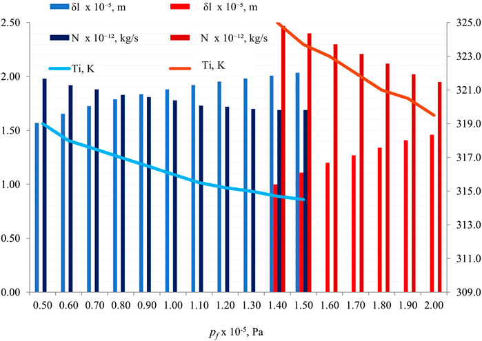
Figure 8. Effect of pf on δl, N, and Ti , with fixed parameters (Tf = 353.2 K, Tp = 293.2 K, Pp= 1 × 10⁵ Pa, r = 1 × 10⁻⁶ m, and δ = 5 × 10⁻⁵ m). Two contact angles are represented: θ = 60° (blue shades) and θ = 82° (red shades).
Here, the contact angle values of 60° and 82° are commonly used in studies to represent different wetting properties of surfaces. A contact angle above 90° indicates hydrophobicity, where the surface repels water, while an angle below 90° signifies hydrophilicity, indicating good wetting by water (Danish, 2020). These specific angles are chosen to represent these distinct wetting behaviors for experimental and analytical purposes. Similarly, the values of 1.0×10⁵ Pa and 1.5 × 10⁵ Pa for pf (pressure) are set to explore the impact of varying pressures on wetting characteristics and interfacial tension in fluid–rock systems. By using different pressure values within this range, researchers can analyze how changes in pressure affect contact angles and interfacial tension, providing insights into the behavior of fluids interacting with rock surfaces under different conditions. These specific pressure values are selected to study a range of scenarios and understand the nuances of fluid–rock interactions comprehensively (Taetz et al., 2016).
This reversal in
3.5 Effect of pp
Figure 9 shows the effect of pp on
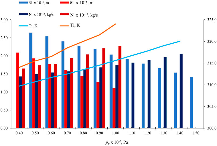
Figure 9. Effect of pp on
In fluid flow, the significance of maintaining a consistent pressure difference (
3.6 Effect of
Figure 10 shows the effect of pf on
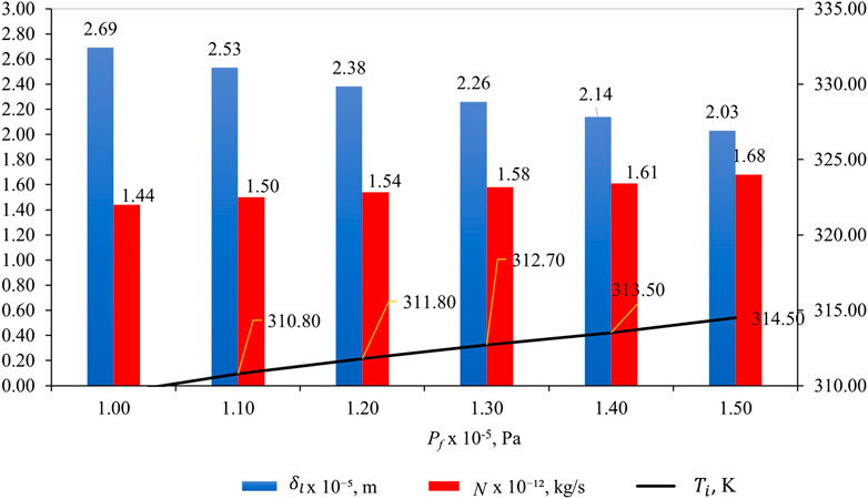
Figure 10. Effect of pf on
Understanding the relationship between liquid intrusion length (
3.7 Effect of
Figure 11 shows the effect of
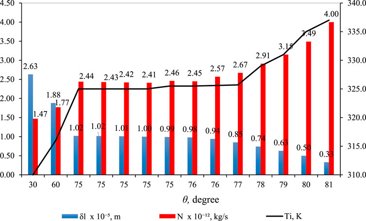
Figure 11. Effect of
In Figure 11 (blue bar),
Figure 12 illustrates the impact of contact angle (θ) on
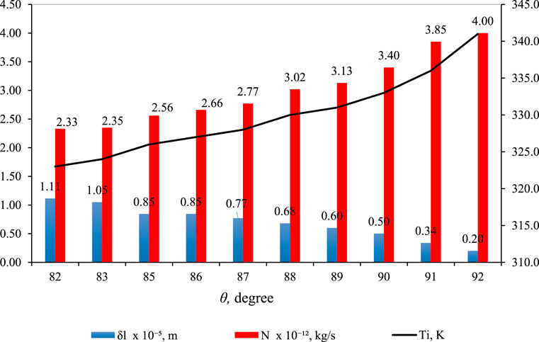
Figure 12. Effect of
However, a key distinction is the use of larger θ values in Figure 12. This adjustment is necessitated by the higher hydrophobicity required in the membrane material to counteract the elevated feed pressure (
In Figure 13, N is graphed against
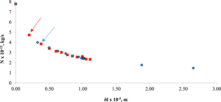
Figure 13. N versus
4 Comparison with the experimental data
The simulation model proposed in this work does not include some factors that would affect the DCMD performance, such as the heat transfer coefficient of the feed and permeate boundary layer and the thermal conductivity of the membrane polymer matrix. Therefore, the agreement of the computational results with the experimental data in their numerical values cannot be tested. Nevertheless, the validity of the model simulation can be examined by comparing the trends it predicts with those observed by experiments. The simulation predicts that the DCMD flux
1) Increases as r increases. (Figure 4)
2) Increases as Tf increases (Figure 5)
3) Decreases as pf increases (Figure 7; Figure 8)
4) Increases as pp increases (Figure 9)
5) Increases as θ increases (Figure 11; Figure 12).
Among those, 1), 2), and 5) are quite obvious and have been proven by many experiments (Khayet and Matsuura, 2011). The trends predicted by 3) and 4) are, however, not quite obvious because only a few studies have examined the effect of Pf and pp on the MD flux. Some of those examples are as follows:
Park and Lee (2019) observed a decrease in the flux with an increase in the feed pressure pf and attributed it to membrane compaction. They also noticed a sudden increase in the flux at a high pressure caused by the pore wetting.
Liu et al. (2022) observed a 62% increase in the initial flux of DCMD when the feed pressure (Pf) was changed from 1 kPa (gauge) to −30 kPa (gauge) for a commercial PVDF membrane. They have explained this phenomenon by 1) considering the contribution of the molecular diffusion and the Knudsen diffusion in the pore and 2) attributing to the increase in the heat transfer coefficient of the boundary layer at the feed side and the reduction in transmembrane heat conduction caused by the change of the meniscus shape from convex to concave.
In summary, the trends observed by the experiments were:
1) Park and Lee (2019) also observed a decrease in the flux with an increase in the feed pressure and attributed it to membrane compaction. They also noticed a sudden increase in the flux at a high pressure caused by the pore wetting.
2) The DCMD flux of the incompressible hollow fiber membrane did not change with an increase in pf (Zhang et al., 2011).
3) The DCMD flux increased with a decrease in pf. It is unlikely the pore deformation occurred when the feed pressure was decreased (Liu et al., 2022).
As for the effect of the increase in pf, the simulation predicts the flux decrease (Figures 7, 8). Thus, the model prediction agrees with experimental results 1) but disagrees with the experimental results 2).
In Zhang et al.’s compression experiments (Zhang et al., 2011), however, pressure was applied to the hollow fiber on both sides, that is, the lumen and the shell side, but in the DCMD experiments, the pressure was applied only to the feed side (likely the lumen side of the hollow fiber according to their article (Zhang et al., 2010)). Then, it is possible that the hollow fiber expanded, resulting in an increase in DCMD flux. If such an expansion did not take place, the flux could decrease with an increase in pf, as the model predicted. The model predicts a slight increase in flux as feed pressure rises, a condition where pf–pp is maintained constant, as depicted in Figure 10. The concept of the liquid intrusion length (
The model simulation, on the other hand, predicts that
5 Conclusion
We developed a simulation model to investigate flux and partial pore wetting in DCMD while considering the influence of capillary pressure at the liquid–gas interface. In this context, we assumed that the contact angle inside the pore was less than 90° due to the high pressure in the gas phase or potential alterations in chemistry at the pore wall. The model predicts that the weight flow rate increases with an increase in the pore radius, rises with higher feed temperature, decreases with an increase in permeate temperature, and increases with an increase in the contact angle. These trends have already been experimentally confirmed by numerous authors.
Regarding the effect of feed pressure (pf), the model predicts a decrease in the permeation rate as feed pressure increases while keeping the permeate pressure constant. This prediction generally aligns with experimental results, except in the case of hollow fibers, which are considered incompressible. Additionally, the model forecasts a decrease in permeation rate with increasing feed pressure while maintaining a constant pressure difference between the feed and permeate, a trend that contradicts certain experimental findings. However, these instances of disagreement can be attributed to the potential expansion of the pore during DCMD experiments.
Furthermore, the model suggests that partial pore wetting is enhanced with an increase in feed pressure when the pore size is as large as 1 μm, which is consistent with experimental results obtained from membranes with an average pore size of 0.67 μm. Conversely, the model predicts an opposite trend when the pore size is as small as 0.1 μm. This prediction warrants further experimental testing to validate its accuracy. According to the model, partial pore wetting diminishes as permeate pressure increases, a trend supported by experimental observations of pore wetting. These findings provide valuable insights into the complex interplay of feed and permeate pressure in the context of DCMD and its potential applications.
These insights deepen our comprehension of the nuanced dynamics within DCMD, shedding light on potential applications. Future research should prioritize rigorous experimental validation and refine the model to encompass diverse membrane characteristics and operating conditions, enhancing its predictive accuracy.
Data availability statement
The raw data supporting the conclusion of this article will be made available by the authors, without undue reservation.
Author contributions
SA: visualization, and writing–original draft. TM: conceptualization, data curation, formal analysis, funding acquisition, investigation, methodology, resources, supervision, validation, visualization, writing–original draft, and writing–review and editing. JJ: conceptualization, funding acquisition, investigation, methodology, project administration, supervision, validation, visualization, writing–review and editing, and data curation. LJ: validation and writing–review and editing. AI: validation and writing–review and editing. MO: validation and writing–review and editing. MA: validation and writing–review and editing.
Funding
The author(s) declare that financial support was received for the research, authorship, and/or publication of this article from the Ministry of Higher Education, Malaysia under HICoE grant, R.J090301.7851.4J433 and from Universiti Teknologi Malaysia under Hi-Tech (F4) grant Q.J130000.4609.00Q14.
Acknowledgments
The authors would like to express gratitude to the Ministry of Higher Education, Malaysia for funding under HICoE grant, R.J090301.7851.4J433 and to Universiti Teknologi Malaysia for the financial funding under Hi-Tech (F4) grant Q.J130000.4609.00Q14.
Conflict of interest
The authors declare that the research was conducted in the absence of any commercial or financial relationships that could be construed as a potential conflict of interest.
The handling editor MK declared a past co-authorship with the author TM.
The author(s) declared that they were an editorial board member of Frontiers, at the time of submission. This had no impact on the peer review process and the final decision.
Publisher’s note
All claims expressed in this article are solely those of the authors and do not necessarily represent those of their affiliated organizations, or those of the publisher, the editors, and the reviewers. Any product that may be evaluated in this article, or claim that may be made by its manufacturer, is not guaranteed or endorsed by the publisher.
References
Alklaibi, A. M., and Lior, N. (2005). Membrane-distillation desalination: status and potential. Desalination 171, 111–131. doi:10.1016/j.desal.2004.03.024
Ashoor, B. B., Mansour, S., Giwa, A., Dufour, V., and Hasan, S. W. (2016). Principles and applications of direct contact membrane distillation (DCMD): a comprehensive review. Desalination 398, 222–246. doi:10.1016/j.desal.2016.07.043
Back, J. O., Brandstätter, R., Spruck, M., Koch, M., Penner, S., and Rupprich, M. (2019). Parameter screening of PVDF/PVP multi-channel capillary membranes. Polym. (Basel) 11, 463. doi:10.3390/polym11030463
Baghbanzadeh, M., Rana, D., Lan, C. Q., and Matsuura, T. (2016). Effects of hydrophilic silica nanoparticles and backing material in improving the structure and performance of VMD PVDF membranes. Sep. Purif. Technol. 157, 60–71. doi:10.1016/j.seppur.2015.11.029
Biswas, D., and Kartha, S. A. (2019). Conceptual modeling of temperature effects on capillary pressure in dead-end pores. Sādhanā 44, 117. doi:10.1007/s12046-019-1108-y
Bolz, R. E. (1973). CRC handbook of tables for applied engineering science. Boca Raton, Florida, United States: CRC Press. doi:10.1201/9781315214092
Camacho, L. M., Dumée, L., Zhang, J., Li, J., Duke, M., Gomez, J., et al. (2013). Advances in membrane distillation for water desalination and purification applications. Water 5, 94–196. doi:10.3390/w5010094
Chesworth, W., Camps Arbestain, M., Macías, F., Spaargaren, O., and Mualem, Y. (2015). Capillary pressure BT - encyclopedia of soil science. in, ed. W. Chesworth (Dordrecht: Springer Netherlands), 81–91. doi:10.1007/978-1-4020-3995-9_87
Chamani, H., Matsuura, T., Rana, D., and Lan, C. Q. (2019). Modeling of pore wetting in vacuum membrane distillation. J. Memb. Sci. 572, 332–342. doi:10.1016/j.memsci.2018.11.018
Danish, M. (2020). Contact angle studies of hydrophobic and hydrophilic surfaces BT - handbook of magnetic hybrid nanoalloys and their nanocomposites. Cham: Springer International Publishing, 1–22. doi:10.1007/978-3-030-34007-0_24-1
Eljaddi, T., and Cabassud, C. (2022). Wetting of photoplasmonic PVDF/silver membranes in photothermal membrane distillation: identification of wetting mechanisms and comparison of wetting dynamics. Desalination 540, 116019. doi:10.1016/j.desal.2022.116019
Feng, X., Jiang, L. Y., Matsuura, T., and Wu, P. (2017). Fabrication of hydrophobic/hydrophilic composite hollow fibers for DCMD: influence of dope formulation and external coagulant. Desalination 401, 53–63. doi:10.1016/j.desal.2016.07.026
Gryta, M. (2005). Long-term performance of membrane distillation process. J. Memb. Sci. 265, 153–159. doi:10.1016/j.memsci.2005.04.049
Gryta, M. (2007). Influence of polypropylene membrane surface porosity on the performance of membrane distillation process. J. Memb. Sci. 287, 67–78. doi:10.1016/j.memsci.2006.10.011
Gryta, M. (2020). Mitigation of membrane wetting by applying a low temperature membrane distillation. Membr. (Basel) 10, 158. doi:10.3390/membranes10070158
Guillen-Burrieza, E., Thomas, R., Mansoor, B., Johnson, D., Hilal, N., and Arafat, H. (2013). Effect of dry-out on the fouling of PVDF and PTFE membranes under conditions simulating intermittent seawater membrane distillation (SWMD). J. Memb. Sci. 438, 126–139. doi:10.1016/j.memsci.2013.03.014
He, F., Gilron, J., Lee, H., Song, L., and Sirkar, K. K. (2008). Potential for scaling by sparingly soluble salts in crossflow DCMD. J. Memb. Sci. 311, 68–80. doi:10.1016/j.memsci.2007.11.056
Hou, C., Pang, Z., Xie, S., Hing Wong, N., Sunarso, J., and Peng, Y. (2023). Enhanced permeability and stability of PVDF hollow fiber membrane in DCMD via heat-stretching treatment. Sep. Purif. Technol. 304, 122325. doi:10.1016/j.seppur.2022.122325
Ibrar, I., Yadav, S., Naji, O., Alanezi, A. A., Ghaffour, N., Déon, S., et al. (2022). Development in forward Osmosis-Membrane distillation hybrid system for wastewater treatment. Sep. Purif. Technol. 286, 120498. doi:10.1016/j.seppur.2022.120498
Jacob, P., Laborie, S., and Cabassud, C. (2018). Visualizing and evaluating wetting in membrane distillation: new methodology and indicators based on Detection of Dissolved Tracer Intrusion (DDTI). Desalination 443, 307–322. doi:10.1016/j.desal.2018.06.006
Karakulski, K., and Gryta, M. (2005). Water demineralisation by NF/MD integrated processes. Desalination 177, 109–119. doi:10.1016/j.desal.2004.11.018
Khayet, M., and Matsuura, T. (2011). Membrane distillation principles and applications. Amsterdam: Elsevier. doi:10.1016/B978-0-444-53126-1.10017-X
Liu, Y., Horseman, T., Wang, Z., Arafat, H. A., Yin, H., Lin, S., et al. (2022). Negative pressure membrane distillation for excellent gypsum scaling resistance and flux enhancement. Environ. Sci. Technol. 56, 1405–1412. doi:10.1021/acs.est.1c07144
Naidu, L. D., Saravanan, S., Chidambaram, M., Goel, M., Das, A., and Babu, J. S. C. (2015). Nanofiltration in transforming surface water into healthy water: comparison with reverse osmosis. J. Chem. 2015, 1–6. doi:10.1155/2015/326869
Pangarkar, B. L., Sane, M. G., Parjane, S. B., and Guddad, M. (2011). Vacuum membrane distillation for desalination of ground water by using flat sheet membrane. https://zenodo.org/records/1070211.
Park, S.-M., and Lee, S. (2019). Influence of hydraulic pressure on performance deterioration of direct contact membrane distillation (DCMD) process. Membr. (Basel) 9, 37. doi:10.3390/membranes9030037
Peña, L., de Zárate, J. M. O., and Mengual, J. I. (1993). Steady states in membrane distillation: influence of membrane wetting. J. Chem. Soc. Faraday Trans. 89, 4333–4338. doi:10.1039/FT9938904333
Peng, P., Fane, A. G., and Li, X. (2005). Desalination by membrane distillation adopting a hydrophilic membrane. Desalination 173, 45–54. doi:10.1016/j.desal.2004.06.208
Peng, Y., Dong, Y., Fan, H., Chen, P., Li, Z., and Jiang, Q. (2013). Preparation of polysulfone membranes via vapor-induced phase separation and simulation of direct-contact membrane distillation by measuring hydrophobic layer thickness. Desalination 316, 53–66. doi:10.1016/j.desal.2013.01.021
Pfeiffer, A. M., Finnegan, N. J., and Willenbring, J. K. (2017). Sediment supply controls equilibrium channel geometry in gravel rivers. Proc. Natl. Acad. Sci. 114, 3346–3351. doi:10.1073/pnas.1612907114
Qtaishat, M., Khayet, M., and Matsuura, T. (2009). Novel porous composite hydrophobic/hydrophilic polysulfone membranes for desalination by direct contact membrane distillation. J. Memb. Sci. 341, 139–148. doi:10.1016/j.memsci.2009.05.053
Rácz, G., Kerker, S., Kovács, Z., Vatai, G. N., Ebrahimi, M., and Czermak, P. (2014). Theoretical and experimental approaches of liquid entry pressure determination in membrane distillation processes. Period. Polytech. Chem. Eng. 58, 81–91. doi:10.3311/PPCH.2179
Rezaei, M., and Samhaber, W. (2016). Wetting behaviour of superhydrophobic membranes coated with nanoparticles in membrane distillation. Chem. Eng. Trans. 47, 373–378. SE-Research Articles. doi:10.3303/CET1647063
Rezaei, M., Warsinger, D. M., Lienhard V, J. H., Duke, M. C., Matsuura, T., and Samhaber, W. M. (2018). Wetting phenomena in membrane distillation: mechanisms, reversal, and prevention. Water Res. 139, 329–352. doi:10.1016/j.watres.2018.03.058
Ritter, M. E. (2022). 18.2: channel Geometry and flow characteristics. Univ. Wisconsin-Stevens Point. Libr., Available at: https://geo.libretexts.org/@go/page/16641 (Accessed March 9, 2024).
Rouquerol, J., Baron, G., Denoyel, R., Giesche, H., Groen, J., Klobes, P., et al. (2011). Liquid intrusion and alternative methods for the characterization of macroporous materials (IUPAC Technical Report). IUPAC Tech. Rep. 84, 107–136. doi:10.1351/PAC-REP-10-11-19
Saffarini, R. B., Mansoor, B., Thomas, R., and Arafat, H. A. (2013). Effect of temperature-dependent microstructure evolution on pore wetting in PTFE membranes under membrane distillation conditions. J. Memb. Sci. 429, 282–294. doi:10.1016/j.memsci.2012.11.049
Shin, Y., Choi, J., Lee, T., Sohn, J., and Lee, S. (2016). Optimization of dewetting conditions for hollow fiber membranes in vacuum membrane distillation. Desalin. Water Treat. 57, 7582–7592. doi:10.1080/19443994.2015.1044266
Sipahutar, W. S., Maulana, S., Augustina, S., Murda, R. A., and Bindar, Y. (2021). Effects of heat treatment on the wettability and color properties of betung bamboo (dendrocalamus asper) strand. IOP Conf. Ser. Earth Environ. Sci. 830, 012071. doi:10.1088/1755-1315/830/1/012071
Stewart, M. I. (2014). Chapter nine - gas sweetening. Boston: Gulf Professional Publishing, 433–539. doi:10.1016/B978-0-12-382207-9.00009-3
Taetz, S., John, T., Bröcker, M., and Spandler, C. (2016). Fluid–rock interaction and evolution of a high-pressure/low-temperature vein system in eclogite from New Caledonia: insights into intraslab fluid flow processes. Contrib. Mineral. Petrol. 171, 90. doi:10.1007/s00410-016-1295-z
Tun, C. M., Fane, A. G., Matheickal, J. T., and Sheikholeslami, R. (2005). Membrane distillation crystallization of concentrated salts—flux and crystal formation. J. Memb. Sci. 257, 144–155. doi:10.1016/j.memsci.2004.09.051
Warsinger, D. M., Servi, A., Connors, G. B., Mavukkandy, M. O., Arafat, H. A., Gleason, K. K., et al. (2017). Reversing membrane wetting in membrane distillation: comparing dryout to backwashing with pressurized air. Environ. Sci. Water Res. Technol. 3, 930–939. doi:10.1039/C7EW00085E
Yazgan-Birgi, P., Hassan Ali, M. I., and Arafat, H. A. (2018). Estimation of liquid entry pressure in hydrophobic membranes using CFD tools. J. Memb. Sci. 552, 68–76. doi:10.1016/j.memsci.2018.01.061
Zhang, J., Li, J.-D., Duke, M., Xie, Z., and Gray, S. (2010). Performance of asymmetric hollow fibre membranes in membrane distillation under various configurations and vacuum enhancement. J. Memb. Sci. 362, 517–528. doi:10.1016/j.memsci.2010.07.004
Zhang, J., Li, J.-D., and Gray, S. (2011). Effect of applied pressure on performance of PTFE membrane in DCMD. J. Memb. Sci. 369, 514–525. doi:10.1016/j.memsci.2010.12.033
Keywords: simulation model, pore wetting, capillary pressure, pore size, hydrophilic membrane, DCMD
Citation: Ahmad SNA, Matsuura T, Jaafar J, Jiang LY, Ismail AF, Othman MHD and A. Rahman M (2024) Modeling pore wetting in direct contact membrane distillation—effect of interfacial capillary pressure. Front. Membr. Sci. Technol. 3:1355598. doi: 10.3389/frmst.2024.1355598
Received: 14 December 2023; Accepted: 22 March 2024;
Published: 26 April 2024.
Edited by:
Mohamed Khayet, Complutense University of Madrid, SpainReviewed by:
Antonio Comite, University of Genoa, ItalyEnrica Fontananova, National Research Council (CNR), Italy
Yuan Liao, Nankai University, China
Copyright © 2024 Ahmad, Matsuura, Jaafar, Jiang, Ismail, Othman and A. Rahman. This is an open-access article distributed under the terms of the Creative Commons Attribution License (CC BY). The use, distribution or reproduction in other forums is permitted, provided the original author(s) and the copyright owner(s) are credited and that the original publication in this journal is cited, in accordance with accepted academic practice. No use, distribution or reproduction is permitted which does not comply with these terms.
*Correspondence: Juhana Jaafar, juhana@petroleum.utm.my