EnViSoRS: Enhanced Vision System for Robotic Surgery. A User-Defined Safety Volume Tracking to Minimize the Risk of Intraoperative Bleeding
 Veronica Penza
 Elena De Momi
 Nima Enayati
 Thibaud Chupin
 Jesús Ortiz
 Leonardo S. Mattos
- 1Nearlab, Department of Electronics, Information and Bioengineering, Politecnico di Milano, Milan, Italy
- 2Biomedical Robotics Lab, Department of Advanced Robotics, Istituto Italiano di Tecnologia, Genoa, Italy
In abdominal surgery, intraoperative bleeding is one of the major complications that affect the outcome of minimally invasive surgical procedures. One of the causes is attributed to accidental damages to arteries or veins, and one of the possible risk factors falls on the surgeon’s skills. This paper presents the development and application of an Enhanced Vision System for Robotic Surgery (EnViSoRS), based on a user-defined Safety Volume (SV) tracking to minimize the risk of intraoperative bleeding. It aims at enhancing the surgeon’s capabilities by providing Augmented Reality (AR) assistance toward the protection of vessels from injury during the execution of surgical procedures with a robot. The core of the framework consists in (i) a hybrid tracking algorithm (LT-SAT tracker) that robustly follows a user-defined Safety Area (SA) in long term; (ii) a dense soft tissue 3D reconstruction algorithm, necessary for the computation of the SV; (iii) AR features for visualization of the SV to be protected and of a graphical gage indicating the current distance between the instruments and the reconstructed surface. EnViSoRS was integrated with a commercial robotic surgical system (the dVRK system) for testing and validation. The experiments aimed at demonstrating the accuracy, robustness, performance, and usability of EnViSoRS during the execution of a simulated surgical task on a liver phantom. Results show an overall accuracy in accordance with surgical requirements (<5 mm), and high robustness in the computation of the SV in terms of precision and recall of its identification. The optimization strategy implemented to speed up the computational time is also described and evaluated, providing AR features update rate up to 4 fps, without impacting the real-time visualization of the stereo endoscopic video. Finally, qualitative results regarding the system usability indicate that the proposed system integrates well with the commercial surgical robot and has indeed potential to offer useful assistance during real surgeries.
1. Introduction
In laparoscopic abdominal surgery, one of the major complications is intraoperative bleeding due to injuries to vessels (Opitz et al., 2005). Main arteries or veins close to the surgical site can be accidentally damaged during the execution of the surgical procedure, activating a chain of secondary effects, including (i) longer surgical procedure time as a result of the extra time needed to find and stop the bleeding source; (ii) longer anesthesia time and related risks; (iii) switching to open-surgery approach and related risks; (iv) post-operative bleeding. These complications have a clear negative effect on the surgery, leading in the worst case scenario to patient death.
The introduction of robotics in surgery has demonstrated to overcome many of the obstacles introduced by laparoscopic techniques, improving the outcome of clinical procedures. The main advantages brought by robotic systems consist in the enhancement of surgeons’ dexterity, restoration of hand-eye coordination, and improvement of surgeons’ ergonomics (Lanfranco et al., 2004; Beyl et al., 2013; Garbin et al., 2015; Bravo et al., 2015). However, even though these benefits lead to improved surgical outcome, adverse events, such as intraoperative bleeding, can still occur during a robotic-assisted surgical procedure. Assistive tools, integrated with the robotic system, aimed at helping the surgeon in identifying and protecting delicate areas, can therefore be valuable to avoid vessel injuries during the surgical procedure. The development of such tools would represent a relevant step toward a safer clinical procedure, improving the surgical success ratio.
Computer-assisted technologies coupled with surgical robotic systems can enhance surgeons’ capabilities by providing additional information regarding the surgical gestures. Specifically, these technologies can be used to intraoperatively identify and track a region of interest bounding a delicate structure. This can be useful to help preventing vessel injuries by giving the surgeon a feedback related to the distance between the instruments and this area. Visual, auditory, or haptic sensory channels can be exploited to augment the operation with such a feedback (Enayati et al., 2016).
The intraoperative identification of vessels to be preserved has been explored using preoperative information registered on the patient and visualized by means of Augmented Reality (AR) systems (Nicolau et al., 2011; Onda et al., 2014). However, this approach has to deal with dynamic changes of the anatomy between the data acquisition (preoperative) phase and the surgical procedure (intraoperative) (Faria et al., 2014). These changes can occur due to (i) different pose of the patient, (ii) CO2 abdominal insufflation, (iii) instrument tissue interaction, (iv) heartbeat, and (v) breathing. In order to overcome these limitations and to update the preoperative/intraoperative registration at run-time, computer vision and image-based tracking algorithms can be exploited to track these areas relying on image characteristics (Stoyanov, 2012). Different attempts have been made in literature for soft tissue tracking in endoscopic images (Yip et al., 2012; Giannarou et al., 2013; Puerto-Souza et al., 2014; Richa et al., 2014). Furthermore, to track the region of interest in the 3D space and to have a more accurate knowledge of the tissue deformation, 3D reconstruction algorithms are exploited to reconstruct the surface of the surgical area (Stoyanov et al., 2010; Röhl et al., 2012; Maier-Hein et al., 2013, 2014). Although such computer vision algorithms have achieved considerable performance, what is still missing is their integration into a surgical robotic system, providing (i) long-term robustness even under difficult circumstances (field of view occlusion from the instruments, presence of blood or smoke, and sudden camera movements), (ii) adaptation to various changes of the environment or of the object itself, and (iii) real-time processing.
Based on previous published work on long-term tissue tracking and dense tissue 3D reconstruction (Penza et al., 2016),1 this work presents an Enhanced Vision System for Robotic Surgery (EnViSoRS) aimed at minimizing the risk of intraoperative bleeding during abdominal RMIS. The objective of this framework is to provide the surgeons with AR features to warn them in case the robotic instruments are approaching a user-defined Safety Area (SA), manually drawn intraoperatively around the tissue to protect. The system has to be robust against common events happening during a surgical procedure, such as (i) camera moved by the surgeon to navigate the surgical field, (ii) tissues deformed while performing surgery, or (iii) field of view suddenly occluded by smoke caused by tissue cauterization or by the instrument itself. Thus, to know at run-time the 3D poses of the SA, a 2D tracking algorithm is used to follow the SA over the sequence of images, and it is exploited as a prior for the coarse identification of the tissue surface to be subsequently reconstructed. The 3D information obtained from this reconstruction is then used to identify a Safety Volume (SV) fitted around the area to protect in the form of an ellipsoid. Any time an instrument approaches the SV, the surgeon is warned by means of a graphical representation of the distance between the instruments and the reconstructed surface. AR is also used to visualize the SV projecting the ellipsoid on the image. The system is integrated into the da Vinci Research Kit (dVRK), a platform provided by Intuitive Surgical Inc. (USA) to advance research in tele-operated robotic surgical systems, for testing and validation under realistic RMIS conditions.
The paper is structured as follows: in Section 2, the system calibration and the state machine framework is described. In addition, the optimization strategy used to run the system at an interactive frame rate is described. In Section 3, accuracy, robustness, performance, and usability of the system are assessed and results are presented in Section 4. Finally, discussion, conclusions, and open issues are reported in Section 5.
2. Materials and Methods
An overview of the proposed framework integrated into the dVRK system (Intuitive Surgical Inc., USA, WPI, and Johns Hopkins University) is shown in Figure 1. The surgeon, in any moment of the surgery, can select the delicate area to protect using a graphics tablet and a stylus. In our configuration, the tablet was located directly on the da Vinci master console, allowing the surgeons to perform this operation while they are seated viewing the images from the stereoendoscope through the 3D display. Once the area is selected, the corresponding SV is computed and displayed using AR (as described in Sec. 2.2). A gage located in the upper right corner of the image warns the surgeon about the distance between the instruments and the reconstructed tissue surface.
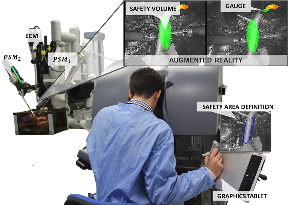
Figure 1. EnViSoRS: Enhanced Vision System to improve Safety in Robotic Surgery integrated into dVRK system (WPI and Johns Hopkins University). From the master console, the surgeon can (i) select the SA using a stylus and a graphics tablet, (ii) check the SV overlaid on the images, and (iii) see a graphical gage warning him/her about the distance between the instruments and the 3D surface of the SV.
2.1. System Calibration
The reference systems involved in EnViSoRS when integrated into the dVRK system are shown in Figure 2. We considered three robotic arms: PSM1 and PSM2 for controlling the left and right instruments; ECM to hold the stereoendoscope. The passive joints of each arm are manually adjusted, locating the Remote Center of Motion (RCM) of the kinematic chain at the skin entry point of the abdomen, in order to maximize the instrument range of motion within the patient-specific workspace. Their reference systems {PSM1}, {PSM2}, and {ECM} are located in the respective RCM (Freschi et al., 2013). In order to know the relationship between the position of the tissue surface and the instrument end-effectors, a common reference system should be defined. In our case, the Cartesian position of the robotic arms (ee1 and ee2) and the camera (cam) were referred w.r.t {PSM1}. Thus, to refer each robotic arm pose to a unique reference system, the following calibrations were performed:
• Arm to Arm calibration: a 3D–3D rigid registration is computed between {PSM1} and {PSM2}, pointing the same set of non-collinear points on a rigid object (a planar squared chessboard for simplicity) through the instrument end-effectors, as shown in Figure 3A. Given these sets of points, a closed-form solution for the least-squares problem is used to find the best rigid transformation between the coordinate systems (Horn, 1987).
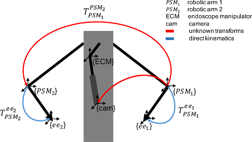
Figure 2. Overview of the reference systems of the da Vinci robotic arms. The blue arrows represent the pose of the two arms (PSM1 and PSM2) given by direct kinematics. The red arrows represent unknown transforms: (i) between PSM1 and PSM2 (ii) between PSM1 and cam, computed as described in Sec. 2.1.
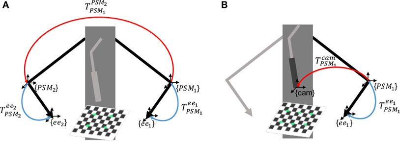
Figure 3. Scheme of the calibrations involved in EnViSoRS. Panel (A) shows the Arm to Arm Calibration between {PSM1} and {PSM2} and panel (B) shows the Arm to Camera calibration between {PSM1} and {cam}; the unknown transformations are reported in red, while the known robotic arm poses in blue.
Consequently, any point in {PSM2} can be referred to {PSM1} as shown in equation (1).
where and are the same point referred to {PSM1} and {PSM2}, respectively.
• Camera calibration: intrinsic camera parameters are computed for both left and right cameras using the OpenCV library (Bradski, 2008). A stereo calibration is also performed to allow image rectification and simplify the process of stereo correspondence in the 3D reconstruction phase.
• Arm to Camera calibration: a 3D–2D rigid registration is computed between {PSM1} and {cam}, identifying the same set of 3D–2D points on a planar squared chessboard, as shown in Figure 3B. The 3D points in {PSM1} are identified pointing eight chessboard corners with the instrument end-effector; the 2D points in {cam} are computed detecting on the image the respective eight corners, using findChessboardCorners OpenCV 3.0 function. Given these sets of points, the rigid transformation between the two reference systems is computed solving an Iterative method based on Levenberg–Marquardt optimization (solvePnP OpenCV 3.0 function).
The computed transformation is used to refer the 3D points, reconstructed by the 3D reconstruction algorithm in {cam}, to {PSM1} with the following equation:
where and pcam are the reconstructed 3D points w.r.t. {PSM1} and {cam}, respectively.
2.2. EnViSorS Framework
EnViSorS framework is organized as a state machine with five states, as shown in Figure 4. A detailed description of each state is provided in the next paragraphs.
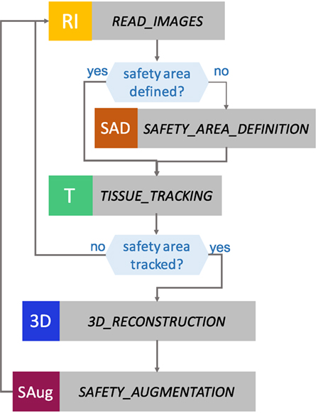
Figure 4. States of the EnViSoRS framework. From top to bottom: in READ IMAGES, the images are captured from the stereo endoscope; in SAFETY AREA DEFINITION, the surgeon can select the safety area to be preserved from injuries; in TISSUE TRACKING, the area is tracked; in 3D RECONSTRUCTION, a dense reconstruction of the tissue surface is computed; and in SAFETY AUGMENTATION, the augmented reality image is generated.
2.2.1. READ_IMAGES State
In the READ_IMAGES state, the left image (imL) and the right image (imR) are acquired and the image distortion is compensated using the camera intrinsic parameters obtained from the camera calibration. In order to reduce the complexity of the stereo correspondence process in the 3D reconstruction, the images are rectified using the extrinsic camera parameters. Specular highlights, produced by the proximity of the source light to wet tissues, can produce erroneous detection of features and 3D reconstructed points. These areas, identified as bright regions with low saturation and high intensity value as described in Penza et al. (2016), are stored in a mask and used in the successive states to prevent errors in tracking and 3D reconstruction.
2.2.2. SAFETY_AREA_DEFINITION State
This state waits until a SA is defined. The SA is a polygonal area, manually identified on imL by the clinician during the surgical procedure. A digital drawing tablet with stylus (WACOM Bamboo Pen and Touch tablet) is used in order to allow the surgeon to ergonomically and precisely draw the desired SA, since its usage has demonstrated to allow highly accurate tracing maneuvers (Deshpande et al., 2014). When the stylus touches the drawing tablet, the surgeon can visualize a green cursor on the image that shows him/her where is located the stylus tip in the image space. The motion of the cursor is relative to the motion of the stylus, i.e., there is no an absolute mapping between the cursor and drawing tablet coordinates. If the stylus button is pressed, a continuous green line, representing the drawn path, is shown on the image. When the button is released, the first and the last defined points are connected to create a closed shape, i.e., the SA contour. Pressing the upper bottom of the tablet, the SA can be deleted. This procedure helps the surgeon to select the SA on the image directly from the console, without the need of any auxiliary monitor.
2.2.3. TISSUE_TRACKING State
LT-SAT (Long-Term Safety Area Tracking) framework, previously developed by Penza et al. (see text footnote 1), is used to robustly track the SA in time. The workflow of LT-SAT tracker is shown in Figure 5, it combines an optical flow algorithm with a tracking-by-detection approach in order to be robust against failures caused by (i) partial occlusion, (ii) total occlusion, (iii) SA out of the field of view, (iv) deformations, (v) illumination changes, (vi) abrupt camera motion, (vii) blur, and (viii) smoke. A Bayesian inference-based approach is used to detect the failure of the tracker, based on online context information. A Model Update Strategy (MUpS) is also used to improve the SA redetection after failures, taking into account the changes of appearance of the SA model due to contact with instruments or image noise.
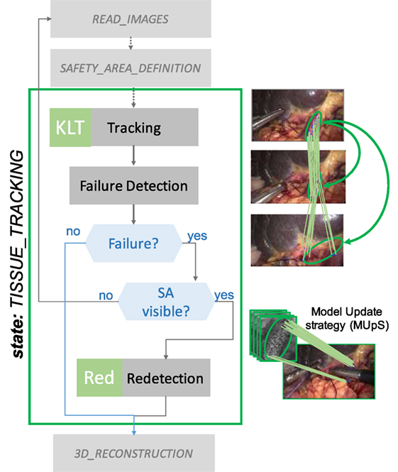
Figure 5. TISSUE_TRACKING state workflow. LT-SAT tracker is used to track the SA. If a failure in the tracking happens, due to (i) partial occlusion, (ii) total occlusion, and (iii) SA out of the field of view, a redetection strategy is used to recover the pose of the SA in the new frame. The Model Update Strategy (MUpS) updates a vector of models to be used for the redetection, taking into account the changes of appearance of the SA model.
2.2.4. 3D_RECONSTRUCTION State
A dense stereo reconstruction algorithm developed by Penza et al. (2016) is used to retrieve the 3D surface information of the tissue contained in the SA. This state is necessary since the LT-SAT framework performs 2D tracking, and we need to localize the SA in 3D at run-time.
An overview of the main steps involved is shown in Figure 6. The 3D reconstruction algorithm is based on a block-matching approach, exploiting a non-parametric Census transform of the images to make the stereo matching more robust against illumination variations (Ma et al., 2013). The tracked SA is exploited as a prior for the coarse identification of the area of the image where to find stereo matches and generate the disparity map. A post-processing step is applied to invalidate incorrect stereo matches, thus leading to a sparser point cloud. In order to improve the density of the reconstructed surface, we proposed a method to refine the disparity map following these steps:
• Simple Linear Iterative Clustering (SLIC) super pixels algorithm (Achanta et al., 2012) is used to segment imL in color-based homogeneous areas;
• The disparity map is segmented using the super pixels previously computed;
• For each segmented part of the disparity map, a plane is computed on the valid values, using locally optimized RANSAC (LO-RANSAC) (Chum et al., 2003);
• The invalid values of the disparity map are replaced with the corresponding points lying on the computed planes.
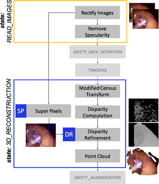
Figure 6. 3D_RECOSTRUCTION state workflow. A dense 3D reconstruction algorithm is used to retrieve the 3D information of the surface contained in the SA. A modified Census Transform makes the stereo matching more robust to illumination variations. SLIC Super Pixel segmentation algorithm is exploited to refine the disparity map, clustering the valid disparity values depending on the homogeneous areas segmented and replacing the invalid values with the strategy described in Sec. 2.2.4.
With respect to previous implementations of this method, a further refinement is performed in order to smooth the reconstructed point cloud. For making this, we consider the disparity image as a 2D Laplace equation problem. The disparity values on the contours of the super pixels are considered as the Dirichlet boundary conditions, and the previously calculated disparity values as the initial conditions of the problem. Then, we use the Gauss–Seidel method with red and black ordering to solve the equations (Krissian et al., 2005). Using this method, the disparity value di,j of each point is updated with the value of the four neighbors according to equation (3). We apply this equation alternatively to the red and black pixels (see Figure 7), and only to the points which are not part of the boundaries (super pixel contours):
where i and j are, respectively, the row and column indices of the image.
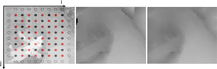
Figure 7. Example of the application of the Gauss–Seidel method to smooth the disparity map, here considered as a 2D Laplace equation problem. On the left, the red and black grid of pixels is shown. In the center and on the right, the disparity map before and after the smoothing, respectively.
In order to create continuity between the super pixel areas, the disparity values at the contour of the super pixels are updated with the average of the 8 neighbor pixels. If the difference between the disparity values of a pixel on the contour is higher than a threshold (θsmooth) the neighbor pixels are also considered as contours, keeping valid the discontinuity. The point cloud is then obtained given the disparity map and the geometry of the stereo setting.
2.2.5. SAFETY_AUGMENTATION State
The aim of SAFETY_AUGMENTATION state is (i) to visualize a stereoscopic AR view of the SV in the 3D display of the da Vinci master console and (ii) to warn the surgeon when the robotic instruments are approaching the reconstructed surface, in order to avoid possible injuries to the delicate area contained in it.
The SV is computed as an ellipsoid fitted on the point cloud, properly transformed in {PSM1} as described in Sec. 2.1. The representation of the SV has to be simple to avoid the excess of information in the image. For that we chose an ellipsoid, which is a simple geometry and also a good approximation.
The Point Cloud Library (PCL) (Rusu and Cousins, 2011) is used to check if the instrument is approaching the point cloud. In particular, spatial neighbor search based on an octree structure is used to calculate the minimum distance between the instruments and the point cloud (using the radiusSearch function of the plc::octree::OctreePointCloudSearch class). If the distance is within the range and below, the surgeon is visually warned.
AR visualization is used in different ways in the different stages of the operation. First, during the SA definition, the AR shows the 2D contour of the SA (Figure 8A). After, during the surgery, the AR visualization displays the SV projected on imL and imR by means of the perspective projection matrices obtained from the stereo camera parameters. Moreover, a graphical gage, overlaid on the top-right corner of the image, indicates to the surgeon the proximity of the instruments with respect to the SV (see Figure 8). These operations were performed using GLFW and OpenGL libraries. The AR features were overlaid on the stereo images and can be deactivated pressing a button located on the tablet.
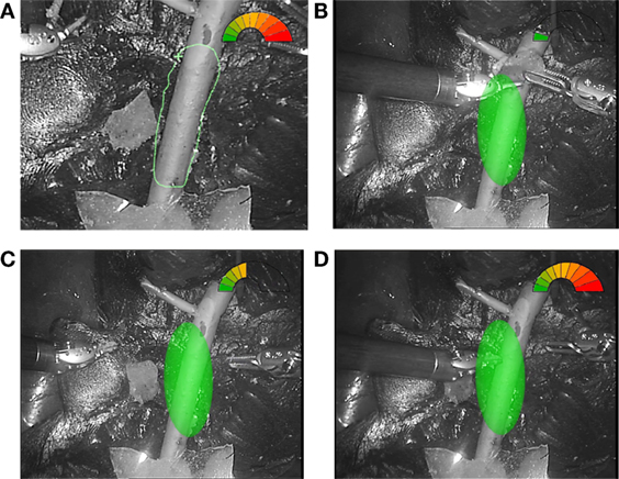
Figure 8. Example of AR visualization. (A) The view of the SA definition; three different situations showing. (B) The instruments performing the surgery in the safe green range. (C) The right instrument approaching the delicate area. (D) The left instrument almost touching the vessel surface and the gage completely red.
2.3. Optimization Strategy
In order to use the framework in a real surgical context, a run-time warning is required to ensure safety during the surgical procedure. To accelerate the processing, and decrease the latency, a multithreading approach was exploited to make the integration of the different algorithms run at interactive frame rates. An overview of the multithreaded pipeline is shown in Figure 9. At the higher level optimization, LT-SAT (T) and the 3D reconstruction (3DR) algorithms are executed in parallel. Since the computational time of the tracker is lower than the 3D reconstruction one, a strategy is implemented to update the previous point cloud (3DRU) until the new version computed in 3D_RECONSTRUCTION state is ready. This strategy makes use of the homography transformation computed by LT-SAT to update the pose of the previous point cloud. We constrain the transformation to translation and rotation on to the xy image plane to avoid the propagation of errors coming from the homography computation. At the lower level, multithreading is also applied to reduce the computational time of both LT-SAT and the 3D reconstruction algorithm:
• SURF feature detection (Bay et al., 2006) is parallelized;
• Super pixels (SP) is executed in parallel to the disparity computation;
• The pixel correspondence during the disparity calculation is parallelized.
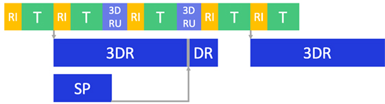
Figure 9. Optimization pipeline. Multithreading was used to improve the computational time: after the images are read (RI), tissue tracking (T), 3D reconstruction and disparity refinement (3DR and DR) are run in separate threads. If 3DR is not completed, an updated version of the old point cloud (3DRU), based on the 2D tracking motion, is used. Super pixel segmentation (SP) is also run in a separate thread.
Moreover, before computing the 3D reconstruction, the image height is scaled down to 288 px, and the width is scaled down accordingly to maintain the aspect ratio. The framework is thought to perform this operation for any image resolution, in order to keep the computational time low and nearly constant, maintaining an acceptable frame rate. In the post-processing phase of the algorithm, the disparity map is re-scaled to its original resolution, exploiting the super pixel refinement to fill gaps (as explained in Sec. 2.2.4).
3. Experimental Evaluation
3.1. System Architecture
The proposed framework was integrated in the dVRK, which consists in proprietary hardware from the first-generation da Vinci “classic” (Intuitive Surgical Inc., USA), and open source electronics and software developed by WPI and Johns Hopkins University (Kazanzides et al., 2014). The system was equipped with a stereo endoscope (resolution 720 × 576, PAL) and the images were captured with a multichannel frame grabber (DeckLink Duo 2, BlackMagic). The program ran on a system with GNU/Linux operating system, with a CPU Intel Core i7-4820K with four cores and hyper-threading (eight virtual cores) and a GPU Nvidia GeForce GTX 780. All the code was written in C++, using OpenCV 3.0 (Bradski, 2008) for the management of the images and with the Robot Operating System (ROS) as framework (Quigley et al., 2009).
3.2. Experimental Protocol
The experiment involved 14 subjects (biomedical engineers with some experience in robotic systems) and 3 surgeons (specialized in robotic surgery in urology), who provided written informed consent in accordance with recommendations from the Politecnico di Milano Ethical committee Board and the Declaration of Helsinki. The task they performed consisted in tele-operating the da Vinci arms to move a piece of polyurethane material (simulating organ tissue removed after excision) from one side of a liver phantom to another and then moving it back (both positions were clearly indicated in the surgical field as shown in Figure 10). The story board of the actions involved is represented in Figure 11. This task was chosen to be simple and repeatable, with the aim to understand the subject’s behavior in managing the instruments in a dangerous situation depending on the presence or not of the AR view, even if it does not represent a meaningful operation for real surgery. The subjects were asked to pay attention to a delicate vessel located between both positions, as shown in Figure 10. Each subject performed 2 sessions, respectively, with and without EnViSoRS; for each session, the task was repeated 2 times. The order of doing it with and without EnViSoRS was determined randomly. The operating field used was a previously developed phantom of human abdomen (Ciullo et al., 2016; Penza et al., under review).2 The surgeons were also asked to give feedback regarding the usability of the system for future improvements.
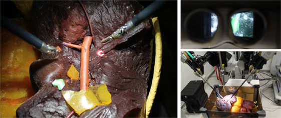
Figure 10. Experimental setup. On the left, the operating field characterized by a liver phantom and a delicate vessel, which is the safety area to be preserved from injuries during surgery. The green arrow and the red target represent, respectively, the starting and the ending point of the task executed by the subjects during the experimental trials. On the top-right, the 3D visor showing the augmented images. On the bottom-right, the da Vinci robotic arms performing the task, tele-operated from the console by the subject.
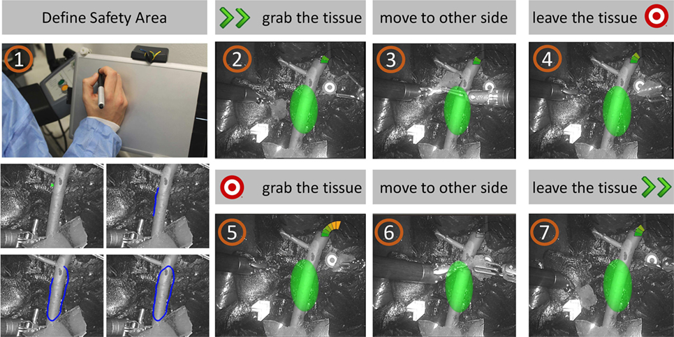
Figure 11. Task storyboard. The subject was asked to (1) define the SA using the stylus and the graphics tablet; (2) grab the piece of tissue from the starting point; (3) move the tissue to the other site of the operating field, paying attention to keep a certain distance from the delicate vessels; (4) leave the tissue to the target point; (5-6-7) repeat the task from the target to the starting point.
3.3. EnViSoRS Evaluation
During the execution of the experiments, different aspects were taken into account: the accuracy, robustness, performance, and usability of EnVisoRS.
The accuracy of the system depends mainly on (i) system calibration errors, (ii) LT-SAT tracker accuracy, and (iii) dense 3D reconstruction performance. The LT-SAT tracker and dense 3D reconstruction algorithm were assessed by Penza et al. (2016), (see text footnote 1 and 2), respectively.
Here, we evaluated the accuracy of (i) intrinsic camera parameters calibration (errintrinsic), (ii) stereo calibration (errstereo), (iii) Arm to Arm calibration (errarm2arm), and (iv) Arm to Camera calibration (errarm2cam).
The Arm to Arm calibration was performed 10 times and, for each trial, errarm2arm was computed as the root mean squared error (RMSE) of the distances between and transformed in {PSM1} using the computed transformation , as described by the following equation:
where d is the Euclidean distance and n is the number of calibration points.
The same protocol was followed for the error evaluation of Arm to Camera calibration and errarm2cam was computed as:
where rp is the re-projection error, are re-projected in {cam} and m is the number of calibration points.
The robustness of the system was evaluated verifying the reliability of the SV projected on the image as AR, validating if its presence was consistent with the SA visible in the image. For each frame during the execution of the task, we created:
• A Ground Truth (GT) in the form of a 2D area representation of the SA on imL; this was created by manually labeling each frame, providing a reference of where the delicate area to be preserved was located on the image.
• A 2D area representing the location of the SV projected on imL (SVAR).
As a measure of consistency between the GT and SVAR, precision (α) and recall (β) were computed as:
where TP is the number of True Positives, FP is the number of False Positives, and FN is the number of False Negatives.
The metrics used to for the definition of TP is the overlap ratio, measured in pixels, and defined as:
TP is the number of frames where the SA is visible and the θ is greater than the overlap ratio threshold and FN is the complementary. FP is the number of frames where the SA is not visible, but it is wrongly tracked.
The precision and recall curves were computed varying the overlap ratio threshold used to identify the TP values. The overlap values were normalized w.r.t the overlap in the first frame, which was verified to be correct. This action was motivated by the fact that the SV is representing an area on the image bigger that the SA, since it is axes aligned; thus, if the SA is not aligned with the axes of its reference frame (as often happens), the resultant SV covers a bigger area.
The performance of the system was evaluated in terms of execution frame rate (fps), computed as:
where T is the average execution time of one loop of the system, computed as the sum of the average computational time of the states involved in each loop. During the experiments, the computational time of each state (RI—Read Images, SAD—Safety Area Definition, KLT—Tracking, Red—Redetection, 3DR—3D reconstruction, 3DRU—3D reconstruction updated, SAug—Safety Augmentation) was measured. Since the sequence of states might change as two different tracking methods were implemented (KLT and Red), T was computed for the 2 possible cases (TOTKLT−3DRU, TOTRed−3DRU). The frame rate of the 3D reconstruction (TOTKLT−3DR) is also reported.
The usability of the EnViSoRS system was evaluated using the System Usability Scale (SUS) questionnaire (Brooke, 1996), which allows the evaluation of surgical technology in terms of general usability (Barresi et al., 2013; Mattos et al., 2014). After each session, the subjects were asked to evaluate the usability of the system assigning a score (from 0—Strongly Disagree—to 14—Strongly Agree) on a continuous line associated with each SUS statement (reported in Table 1). Following the standard convention, the subjects’ scores for each question was normalized to 4, reported to positive score if the statement had a negative sense, and converted to a new number. Then, the statement’s score were added together and multiplied by 2.5 to convert the original scores of 0–40 to 0–100, as stated in the following equation:
where qi is the score for each question normalized to 4. The mean percentage score (mean %score) was also computed for each single statement to highlight weaknesses and strengths of adding EnViSoRS to the standard surgical robotic system. Since the population is normal, a statistical test (Wilcoxon p < 0.05) was used to verify a statistical significance of the result.
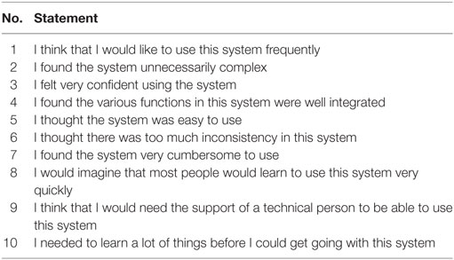
Table 1. Statements of System Usability Scale (SUS) questionnaire.
Moreover, during the execution of the sessions, the Euclidean distance between the instrument tips and the point cloud was measured for both conditions: without (distancestandard) and with EnViSoRS (distanceEnViSoRS). In this case, since the population resulted normal, a parametric statistical test (Wilcoxon p < 0.05) was computed to assess if there was a significance difference between the conditions. The parameters used during the evaluation are listed in Table 2.
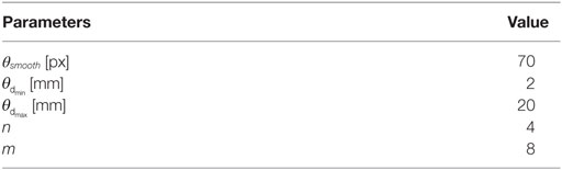
Table 2. Parameters used in the evaluation.
4. Results
The errors computed in the system calibration process are reported in Table 3. The intrinsic and stereo camera calibration errors, are, respectively, errintrinsic = 0.13 ± 0.05 and errstereo = 0.15 ± 0.06, comparable with the errors reported in literature. The error involved in the calibration between PSM1 and PSM2 reference systems is errarm2arm = 1.60 ± 0.2 [mm] and the calibration between the left camera and PSM1 reference system is errarm2cam = 2.02 ± 0.46 [px].
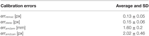
Table 3. Accuracy evaluation: system calibration errors.
The overall error of the system is represented in Figure 12 through precision and recall curves, used for the evaluation of EnViSoRS robustness. The Area Under the Curve (AUC) for precision and recall measure is 0.898 and 0.932, respectively.
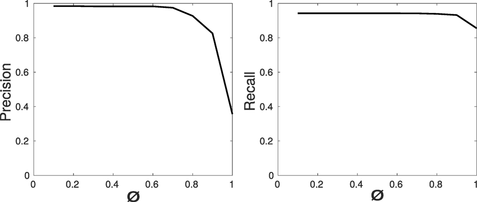
Figure 12. Robustness evaluation: precision and recall curves for the video sequences of the sessions performed by the subjects.
Table 4 reports the computational time of each state, the average execution time of one loop for the two possible state sequences, and the resulting frame rate (fps). Since the dimension of the SA might change overtime, the computational time (time) is expressed in [μs/px]. To illustrate the results, the estimated time necessary for processing an area of 100 × 50px (timearea) is also reported.
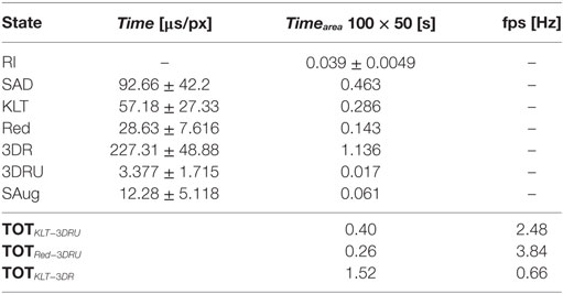
Table 4. Performance evaluation: computational time of each state-of-the-art machine.
During the execution of the task in the session without EnViSoRS, the average distance between the instruments and the 3D reconstructed surface (distancestandard) was 16.0 ± 7.2 [mm], while using EnViSORS such distance (distanceEnViSoRS) was equal to 13.6 ± 4.6 [mm]. The statistical test performed did not report any significant difference.
Table 5 reports the results of the questionnaire. The first and the second column show the mean %score obtained for each statement reported in Table 1, respectively, for the standard system and for EnViSoRS. The third column presents the percentage improvement brought by EnViSoRS. We can see how in most of the aspects the EnViSoRS improve the usability of the system with respect to the standard condition. The total improvement is 4.47%.
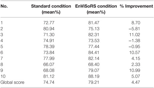
Table 5. SUS questionnaire results: score obtained for each question of Table 1 from the evaluation of the standard system vs. using EnViSoRS, and % of improvement.
5. Discussion and Conclusion
This paper describes EnViSoRS, a computer vision framework aimed at improving the safety during robotic minimally invasive surgery by lowering the risk of bleeding due to vessel injuries. EnViSoRS allows the selection of an area of interest, the SA, to be protected. Then, it presents to the surgeon: (i) the 3D location of this area projected on the stereo surgical images by means of AR and (ii) a graphical gage indicating the current distance between the instruments and the tissue surface, thus warning the surgeon in case the instruments are too close to the delicate area.
The core of EnViSoRS is made of (i) a dense 3D reconstruction algorithm to retrieve tissue surface information contained in the SA and (ii) long-term safety area tracker (LT-SAT) able to track the SA even under difficult circumstances. The added value of this work is the integration of EnViSoRS into dVRK, which was done to demonstrate the integration of the proposed computer vision framework into a state-of-the-art robotic surgical system, thus shortening the distance to a future real application of the technology.
The accuracy of EnViSoRS is affected by different sources of error caused by (i) system calibrations, (ii) 3D reconstruction, and (iii) tracking, influencing the SV computation and representation. Unfortunately, due to different metrics used to evaluate each algorithm, it is difficult to extrapolate a unique error value. An overall evaluation is provided by the precision and recall values computed considering the overlap between SVAR and GT. The correspondent high AUC values demonstrate the robustness of the system, in the sense that, once the SA is selected, the chain of LT-SAT tracker, 3D reconstruction, and AR computes the SV properly when the SA is visible. Of course, errors in the order of millimeters, particularly coming from the calibration process and 3D reconstruction computation, are present, but still in accordance with the clinical requirements (<5 mm). In addition, the minimum and maximum distances displayed by the graphical gage were set to ensure the overall accuracy error does not affect safety or the surgeon’s gestures.
The performance in terms of computational time shows an average frame rate ranging from 2.5fps to 4fps, depending on the computation path. This range of fps cannot be considered real time (≃15–20 fps) and can affect the system in case of fast motion by not correctly updating the surgeon about the current tissue-instrument distance. However, during the experimental trials, the frame rate did not cause discomfort to the users since EnViSoRS does not add any delay to the visualization of the stereo endoscopic images.
Results from the SUS questionnaire show a higher global score using EnViSoRS w.r.t. the standard system, even if the 4.47% improvement is not statistically representative. From a quantitative point of view, the analysis of the distances of the instruments from the reconstructed surface indicates that the subjects tended to keep the instruments further away from the delicate area when performing the task without the support of EnViSoRS. This behavior is not statistically significant given the data obtained during this study, but indeed reflects a feedback provided by the users, i.e., that they felt more confident about moving the surgical tool near the delicate area when it was highlighted by the system. In real clinical applications, this may contribute to shorten the paths followed by the robotic arms, and thus the amount of movement performed by the surgeon, leading to reduced fatigue during long procedures. As part of the experimental protocol described in Sec. 3.2, the feedback given by the surgeons were (i) the process of defining the SA on the image could be more intuitive if performed with the robotic system master, (ii) it would be beneficial to automate the detection of the vessels in the operating field, (iii) they would prefer a more precise shape of the 3D area augmented on the image, instead of an ellipsoid, and (iv) they would like to have easy control over the activation/deactivation of these features during surgery.
In the current integration of the system to dVRK, it has to be pointed out that the ECM arm could not be controlled from the master console. We believe that this factor was not affecting the usability evaluation of the system, that was more based on how the subject was perceiving helpful the AR view to perform the action being aware of the distance between the instruments and the delicate area. Of course, the static position of the camera was simplifying the LT-SAT tracker performance, that anyway was made challenging by the continuous occlusion from the instruments while performing the task.
There are still some limits in the system development and evaluation protocol, which can be improved. Regarding the development, one of these is the representation of the SV as an ellipsoid fitted on the reconstructed point cloud. In this implementation, it is not aligned with the main axes of the reconstructed point cloud, but with the robotic arm reference system, perhaps introducing troubles for the surgeon due to a mismatch between the ellipsoid projection borders and the drawn SA contour. Moreover, the ellipsoid cannot take into account particular shape of the point cloud (e.g., L or C shape). Future implementations will aim at improving the SV shape, for example, representing the SV directly based on the reconstructed point cloud. Regarding the evaluation protocol, another limit could be in evaluating the usability having as surgical scene a phantom of abdomen instead of ex vivo organs or animal surgery. Unfortunately, it is difficult to find ex vivo tissues with visible vessels and connective tissue representing a surgical scenario close to the real one and to conserve it to allow the repetition of the trials in different days. A further analysis involving surgery performed on pigs will be considered for future evaluations to add relevant results.
Overall, EnViSoRS has demonstrated to add novel and promising features to a surgical robotic system used worldwide. To further improve the robustness and usability of the system, future work will aim at improving the system under different aspects: (i) improving the accuracy of the system calibrations using more sophisticated techniques that does not require the use of the da Vinci instruments to measure external objects, (ii) improving LT-SAT tracker to make it more robust against tissue deformations, and (iii) speeding up the computation time, for example, exploiting the potentiality of CPU-GPU processing.
Ethics Statement
All the subjects involved in the experiment provided written informed consent in accordance with recommendations from the Politecnico di Milano Ethical commitee and the Declaration of Helsinki.
Author Contributions
VP developed the main core of EnViSoRs system (LT-SAT tracker, 3D reconstruction algorithm, safety augmentation, system calibrations), performed the experimental evaluation with da Vinci system, the analysis of the results, and the manuscript writing and revision. EM supervised the method development, the results analysis, and the manuscript drafting and revision. NE worked on setting up the dVRK and supervised the experimental setup with da Vinci system. TC implemented the keying of AR on the images and performed results analysis. JO supervised the code optimization and the AR implementation and contributed to manuscript drafting. LM supervised the method development, the experimental protocol, the result analysis, and the manuscript drafting and revision.
Conflict of Interest Statement
The authors declare that the research was conducted in the absence of any commercial or financial relationships that could be construed as a potential conflict of interest.
Acknowledgments
Authors would like to thank Giacinto Barresi for his kind suggestions on the system usability evaluation. Also, authors would like to thank Andrea Russo, MD; Roberto Bianchi, MD; Prof. Marco Elli; and Gianluca Sampogna, MD for the collaboration in the experimental evaluation and their expert feedbacks.
Funding
This project has received funding from the European Union’s Horizon 2020 research and innovation programme under grant agreement No. H2020-ICT-2016-732515.
Abbreviations
EnViSoRS, enhanced vision system for robotic surgery; SA, safety area; SV, safety volume; GT, ground truth; SUS, system usability scale; LT-SAT, long-term safety area tracking.
Footnotes
- ^Penza, V., Du, X., Stoyanov, D., Forgione, A., De Mattos, L., and De Momi, E. (2017). Long term safety area tracking (LT-SAT) with online failure detection and recovery for robotic minimally invasive surgery. Med. Image Anal. (Under Review).
- ^Penza, V., Ciullo, A. S., Moccia, S., Mattos, L. S., and De Momi, E. (2017). Endoabs dataset: endoscopic abdominal stereo image dataset for benchmarking 3D stereo reconstruction algorithms. IEEE Trans. Med. Imag. Spec. Issue Simul. Synth. Med. Imag. (Under Review).
References
Achanta, R., Shaji, A., Smith, K., Lucchi, A., Fua, P., and Süsstrunk, S. (2012). Slic superpixels compared to state-of-the-art superpixel methods. IEEE Trans. Pattern Anal. Mach. Intell. 34, 2274–2282. doi:10.1109/TPAMI.2012.120
Barresi, G., Deshpande, N., Mattos, L. S., Brogni, A., Guastini, L., Peretti, G., et al. (2013). “Comparative usability and performance evaluation of surgeon interfaces in laser phonomicrosurgery,” in Intelligent Robots and Systems (IROS), 2013 IEEE/RSJ International Conference on (Tokyo: IEEE), 3610–3615.
Bay, H., Tuytelaars, T., and Van Gool, L. (2006). “Surf: speeded up robust features,” in European Conference on Computer Vision (Graz: Springer), 404–417.
Beyl, T., Nicolai, P., Raczkowsky, J., Wörn, H., Comparetti, M. D., and De Momi, E. (2013). “Multi kinect people detection for intuitive and safe human robot cooperation in the operating room,” in 16th International Conference on Advanced Robotics (ICAR) (IEEE), 1–6.
Bravo, R., Arroyave, M., Trépanier, J., and Lacy, A. (2015). Robotics in general surgery: update and future perspectives. Adv. Robot. Autom. S2:003. doi:10.4172/2168-9695.S2-003
Chum, O., Matas, J., and Kittler, J. (2003). “Locally optimized ransac,” in Joint Pattern Recognition Symposium (Magdeburg: Springer), 236–243.
Ciullo, A., Penza, V., Mattos, L., and De Momi, E. (2016). Development of a Surgical Stereo Endoscopic Image Dataset for Validating 3D Stereo Reconstruction Algorithms. Pisa: 6th Joint Workshop on New Technologies for Computer/Robot Assisted Surgery (CRAS).
Deshpande, N., Ortiz, J., Caldwell, D. G., and Mattos, L. S. (2014). “Enhanced computer assisted laser microsurgeries with a virtual microscope based surgical system,” in IEEE International Conference on Robotics and Automation (ICRA) (Hong Kong: IEEE), 4194–4199.
Enayati, N., De Momi, E., and Ferrigno, G. (2016). Haptics in robot-assisted surgery: challenges and benefits. IEEE Rev. Biomed. Eng. 9, 49–65. doi:10.1109/RBME.2016.2538080
Faria, C., Sadowsky, O., Bicho, E., Ferrigno, G., Joskowicz, L., Shoham, M., Vivanti, R., and De Momi, E. (2014). Validation of a stereo camera system to quantify brain deformation due to breathing and pulsatility. Med. Phys. 41:113502. doi:10.1118/1.4897569
Freschi, C., Ferrari, V., Melfi, F., Ferrari, M., Mosca, F., and Cuschieri, A. (2013). Technical review of the da vinci surgical telemanipulator. Int. J. Med. Robot. Comput. Assist. Surg. 9, 396–406. doi:10.1002/rcs.1468
Garbin, N., Di Natali, C., Buzzi, J., De Momi, E., and Valdastri, P. (2015). Laparoscopic tissue retractor based on local magnetic actuation. J. Med. Dev. 9:011005.
Giannarou, S., Visentini-Scarzanella, M., and Yang, G.-Z. (2013). Probabilistic tracking of affine-invariant anisotropic regions. IEEE Trans. Pattern Anal. Mach. Intell. 35, 130–143. doi:10.1109/TPAMI.2012.81
Horn, B. K. (1987). Closed-form solution of absolute orientation using unit quaternions. JOSA A 4, 629–642. doi:10.1364/JOSAA.4.000629
Kazanzides, P., Chen, Z., Deguet, A., Fischer, G. S., Taylor, R. H., and DiMaio, S. P. (2014). “An open-source research kit for the da vinci® surgical system,” in Robotics and Automation (ICRA), 2014 IEEE International Conference on (Hong Kong: IEEE), 6434–6439.
Krissian, K., Kikinis, R., Westin, C.-F., and Vosburgh, K. (2005). “Speckle-constrained filtering of ultrasound images,” in Computer Vision and Pattern Recognition, 2005. CVPR 2005. IEEE Computer Society Conference on, Vol. 2 (San Diego, CA: IEEE), 547–552.
Lanfranco, A. R., Castellanos, A. E., Desai, J. P., and Meyers, W. C. (2004). Robotic surgery: a current perspective. Ann. Surg. 239, 14–21. doi:10.1097/01.sla.0000103020.19595.7d
Ma, L., Li, J., Ma, J., and Zhang, H. (2013). “A modified census transform based on the neighborhood information for stereo matching algorithm,” in Image and Graphics (ICIG), 2013 Seventh International Conference on (Qingdao: IEEE), 533–538.
Maier-Hein, L., Groch, A., Bartoli, A., Bodenstedt, S., Boissonnat, G., Chang, P.-L., et al. (2014). Comparative validation of single-shot optical techniques for laparoscopic 3-D surface reconstruction. IEEE Trans. Med. Imaging 33, 1913–1930. doi:10.1109/TMI.2014.2325607
Maier-Hein, L., Mountney, P., Bartoli, A., Elhawary, H., Elson, D., Groch, A., et al. (2013). Optical techniques for 3D surface reconstruction in computer-assisted laparoscopic surgery. Med. Image Anal. 17, 974–996. doi:10.1016/j.media.2013.04.003
Mattos, L. S., Deshpande, N., Barresi, G., Guastini, L., and Peretti, G. (2014). A novel computerized surgeon–machine interface for robot-assisted laser phonomicrosurgery. Laryngoscope 124, 1887–1894. doi:10.1002/lary.24566
Nicolau, S., Soler, L., Mutter, D., and Marescaux, J. (2011). Augmented reality in laparoscopic surgical oncology. Surg. Oncol. 20, 189–201. doi:10.1016/j.suronc.2011.07.002
Onda, S., Okamoto, T., Kanehira, M., Suzuki, F., Ito, R., Fujioka, S., et al. (2014). Identification of inferior pancreaticoduodenal artery during pancreaticoduodenectomy using augmented reality-based navigation system. J. Hepatobiliary Pancreat. Sci. 21, 281–287. doi:10.1002/jhbp.25
Opitz, I., Gantert, W., Giger, U., Kocher, T., and Krähenbühl, L. (2005). Bleeding remains a major complication during laparoscopic surgery: analysis of the salts database. Langenbecks Arch. Surg. 390, 128–133. doi:10.1007/s00423-004-0538-z
Penza, V., Ortiz, J., Mattos, L. S., Forgione, A., and De Momi, E. (2016). Dense soft tissue 3D reconstruction refined with super-pixel segmentation for robotic abdominal surgery. Int. J. Comput. Assist. Radiol. Surg. 11, 197–206. doi:10.1007/s11548-015-1276-0
Puerto-Souza, G. A., Cadeddu, J. A., and Mariottini, G.-L. (2014). Toward long-term and accurate augmented-reality for monocular endoscopic videos. IEEE Trans. Biomed. Eng. 61, 2609–2620. doi:10.1109/TBME.2014.2323999
Quigley, M., Conley, K., Gerkey, B., Faust, J., Foote, T., Leibs, J., et al. (2009). “Ros: an open-source robot operating system,” in ICRA Workshop on Open Source Software, Vol. 3 (Kobe, Japan), 5.
Richa, R., Linhares, R., Comunello, E., von Wangenheim, A., Schnitzler, J.-Y., Wassmer, B., et al. (2014). Fundus image mosaicking for information augmentation in computer-assisted slit-lamp imaging. IEEE Trans. Med. Imaging 33, 1304–1312. doi:10.1109/TMI.2014.2309440
Röhl, S., Bodenstedt, S., Suwelack, S., Kenngott, H., Müller-Stich, B. P., Dillmann, R., et al. (2012). Dense gpu-enhanced surface reconstruction from stereo endoscopic images for intraoperative registration. Med. Phys. 39, 1632–1645. doi:10.1118/1.3681017
Rusu, R. B., and Cousins, S. (2011). “3D is here: point cloud library (pcl),” in Robotics and Automation (ICRA), 2011 IEEE International Conference on (Shanghai: IEEE), 1–4.
Stoyanov, D., Scarzanella, M. V., Pratt, P., and Yang, G.-Z. (2010). “Real-time stereo reconstruction in robotically assisted minimally invasive surgery,” in International Conference on Medical Image Computing and Computer-Assisted Intervention (Beijing: Springer), 275–282.
Keywords: long-term tissue tracker, dense 3D reconstruction, safety area, robotic surgery, augmented reality
Citation: Penza V, De Momi E, Enayati N, Chupin T, Ortiz J and Mattos LS (2017) EnViSoRS: Enhanced Vision System for Robotic Surgery. A User-Defined Safety Volume Tracking to Minimize the Risk of Intraoperative Bleeding. Front. Robot. AI 4:15. doi: 10.3389/frobt.2017.00015
Received: 16 February 2017; Accepted: 25 April 2017;
Published: 24 May 2017
Edited by:
Juan Wachs, Purdue University, USAReviewed by:
Vincenzo Ferrari, University of Pisa, ItalyLior Shamir, Lawrence Technological University, USA
Copyright: © 2017 Penza, De Momi, Enayati, Chupin, Ortiz and Mattos. This is an open-access article distributed under the terms of the Creative Commons Attribution License (CC BY). The use, distribution or reproduction in other forums is permitted, provided the original author(s) or licensor are credited and that the original publication in this journal is cited, in accordance with accepted academic practice. No use, distribution or reproduction is permitted which does not comply with these terms.
*Correspondence: Veronica Penza, veronica.penza@polimi.it;
Elena De Momi, elena.demomi@polimi.it