Signal-Based Self-Organization of a Chain of UAVs for Subterranean Exploration
 Pierre Laclau
 Vladislav Tempez
 Franck Ruffier
 Enrico Natalizio
 Jean-Baptiste Mouret
- 1Inria, CNRS, Université de Lorraine, LORIA, Nancy, France
- 2Université de Technologie de Compiègne (UTC), Compiègne, France
- 3Aix Marseille Université, CNRS, ISM, Marseille, France
- 4Université de Lorraine, CNRS, LORIA, Nancy, France
- 5Autonomous Robotics Research Centre, Technology Innovation Institute, Abu Dhabi, United Arab Emirates
Miniature multi-rotors are promising robots for navigating subterranean networks, but maintaining a radio connection underground is challenging. In this paper, we introduce a distributed algorithm, called U-Chain (for Underground-chain), that coordinates a chain of flying robots between an exploration drone and an operator. Our algorithm only uses the measurement of the signal quality between two successive robots and an estimate of the ground speed based on an optic flow sensor. It leverages a distributed policy for each UAV and a Kalman filter to get reliable estimates of the signal quality. We evaluate our approach formally and in simulation, and we describe experimental results with a chain of 3 real miniature quadrotors (12 by 12 cm) and a base station.
1 Introduction
Thousands of subterranean networks permeate the underground: caves, utility tunnels, abandoned mines, underground quarries, sewers, etc. These voids often need to be mapped and inspected, typically to ensure the safety of new buildings or tunnels, but also in case of obstruction or intrusions.
Robots would greatly help the inspection of these networks, which are often too confined for humans (e.g., sewer pipes) or too dangerous (caves, abandoned mines, collapsed buildings) (Morris et al., 2006). However, designing such robots is challenging. Firstly, they need very good off-road abilities, as the floor is typically uneven, with steep inclines, and sometimes flooded. Secondly, they have to be small enough to fit into tunnels that are often too narrow for humans. Overall, ground robots (wheels or tracks) are either too small to clear large obstacles or too big to enter narrow voids.
Flying robots (Unmanned Aerial Vehicles–UAVs) are a promising alternative to ground robots for subterranean operations (Freire and Cota, 2017; Preston and Roy, 2017; Rogers et al., 2017; Jones et al., 2019; Mansouri et al., 2019). As they fly, they are not impaired by obstacles or liquid on the floor. They can also easily fly over steep inclines, stairs, and even ladders. In addition, current quadrotors are cheap, well understood, and miniaturized. For instance, the Crazyflie is a research quadrotor that fits in a 12 × 12 cm square (rotors included) and weighs less than 40 g (Giernacki et al., 2017).
Unfortunately, small flying robots cannot carry a cable to stay connected with the operator, contrary to ground robots. Instead, they have to rely on a radio link, which works well in open air environments but is challenging in subterranean environments (Akyildiz et al., 2009; Khuwaja et al., 2018). In particular, a typical signal such as the one used by Crazyflie (2.4 GHz radio system) does not penetrate large amount of rocks and are heavily perturbed by metallic pipes. This means that the radio works underground only when there exists an unobstructed path between the emitter and the receiver: at each turn of a corridor, the signal is severely deteriorated or lost.
In this paper, we introduce a distributed algorithm, called U-Chain (for Underground-chain), that coordinates a chain of UAVs, so that UAVs act as relays between an exploration drone and an operator (Figure 1). Our algorithm assumes that the UAVs are flying in a tunnel, but it only uses the measurement of the signal quality between each couple of UAVs and an estimate of the ground velocity based on an optic flow sensor. It does not need any localization system (e.g., a visual SLAM algorithm) and, as such, (1) it naturally adapts to the material and the topography of the tunnel and (2) it works on miniature platforms with limited computational power. For instance, our algorithm will place a relay at a corner (without knowing that it is a corner), but it will also increase the number of relays if the signal is highly perturbed in a specific zone for an unknown reason.
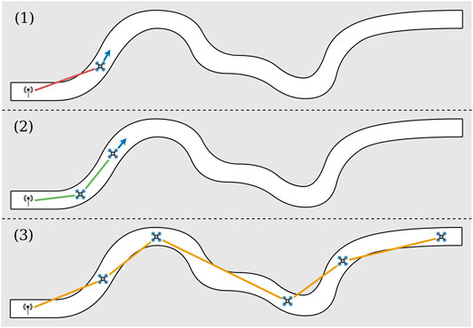
FIGURE 1. Illustration of the U-chain algorithm to maintain a communication chain in a tunnel. A human operator controls an explorer UAV in a tunnel. When the signal strength becomes too weak (1), a new autonomous UAV takes off and acts as a relay by finding the best relay position (2). The objective is the exploration of an environment at any distance, while maximizing the global signal quality (3).
We show formally that maximizing the signal quality of a communication chain in a tunnel is equivalent to equalizing the signal quality between the UAVs, which leads to a simple positioning algorithm for the UAVs. Nonetheless, the signal quality depends on many parameters besides the distance between two UAVS, which results in a noisy value. To address this challenge, we introduce a Kalman filter that leverages optic flow-based measurements of the ground speed. We study the algorithm extensively in simulation and report experimental results on a chain of 3 miniature quadrotors and a base station.
2 Background
Most of the work about subterranean exploration has been focused on a single wheeled or tracked robot (Morris et al., 2006) that is coupled with a SLAM algorithm to build a 3-D map (Thrun et al., 2004). Single UAVs are, however, increasingly tested in mines and they show promising results (Freire and Cota, 2017; Preston and Roy, 2017; Jones et al., 2019; Mansouri et al., 2019). They have, for instance, been deployed by many teams during the DARPA Subterranean Challenge (https://www.subtchallenge.com/, 2020).
In parallel, many algorithms have been proposed for exploring unknown environments with a group of robots, with or without maintaining a permanent connection, and with or without a global coordination (Dorigo et al., 2013; Amigoni et al., 2017). To our knowledge, the vast majority of algorithms assume that the robots explicitly estimate their absolute or relative positions (Pei et al., 2010; Stump et al., 2011; Cesare et al., 2015; Amigoni et al., 2017; Nestmeyer et al., 2017), which they can share with the other robots, and sometimes know the environment beforehand (Hsieh et al., 2008; Stump et al., 2011). Using a positioning system makes sense in outdoor situations, in which the GPS signal is available, and indoor when each robot embeds a SLAM algorithm. Nevertheless, underground miniature UAVs cannot use GPS and they do not have the computational power and sensors needed for accurate SLAM. A notable exception for outdoor networks is the work of Hauert et al. (2009), which leverages an evolutionary algorithm to find a reactive strategy that maintains the network without positioning information.
Signal quality estimates are often considered too unreliable to solely drive the organization of the group of robots (Amigoni et al., 2017), in particular because it is influenced by many factors that are unknown from the robots and therefore not modeled (Amigoni et al., 2017; Khuwaja et al., 2018). Nonetheless, they were recently used in an exploration algorithm for the Crazyflie quadrotors (the same quadrotors as those used in the present work) (McGuire et al., 2019) for three purposes: (1) going back to the base station (by following the gradient of signal quality between the quadrotor and the base), (2) avoiding the other robots (by looking at the inter-quadrotor signal quality), and (3) adapting the exploration direction (by choosing directions that move away from the other quadrotors). This latter system shows that the signal quality can be useful, but it assumes that the base station can always communicate with the UAVs: the objective is not to maintain the communication, but to explore with a lightweight strategy based on reactive behaviors and a state machine.
In the present work, robots are assumed to be in a tunnel, which means they only need to decide if they go forward or backward to maintain the connectivity: this simplifies the coordination problem. In that particular situation, we hypothesize that the signal quality estimates can be sufficient to maintain a chain of communication. This kind of signal-based coordination was investigated in the particular case of subterranean tunnels by Rizzo et al. with wheeled robots (Rizzo et al., 2013). In their article, the authors analyze experimentally and theoretically the signal propagation in tunnels to obtain the general characteristic parameters; they describe a technique that uses these parameters to coordinate robots. While this approach is successful, it assumes a precise identification of the parameters of the radio signal before deployment, which we cannot obtain while exploring unknown environments. Moreover, the approach of Rizzo et al. slightly differs from ours in their objective: while they aim at keeping the quality greater than a minimum threshold, our algorithm maximizes the global quality of the connection.
3 Problem Formulation
We consider a chain of UAVs in a corridor without any positioning system. The general objective is to maintain a high-quality connection between each UAV and the next so that the first UAV of the chain can communicate with the last one. As the UAVs are in a corridor, they only need to decide whether to move forward or backward (the turning is managed by a separate algorithm); they base their decision on the estimates of the signal quality (RSSI—Received Signal Strength Indicator) with the previous UAV and with the next UAV in the chain.
Since the network is organized as a linear formation, a good way of estimating the global signal strength is by finding the relay link with the lowest chances of successfully transmitting the packet. We will call it the worst bottleneck in the communication chain. In this problem, this corresponds to maximizing the worst signal quality between two consecutive UAVs in the communication chain.
3.1 Notations
3.2 Assumptions
All agents position themselves at the centerline of the tunnel, equidistant from each wall (this is achieved with the centering policy, Section 5).
The function
The growth of s is bounded by k (i.e., it verifies k-Lipschitz continuity):
•
•
We neglect the communication time (in our experience, our UAVs need less than 0.25 ms to send a packet, which is much faster than the overall dynamics of the chain of drones).
3.3 Objective Function
An optimal configuration is the solution of:
that is, we search for the set of positions that maximizes the signal quality of the weakest link. This corresponds to a traditional “max-min” decision rule (Jaffe, 1981).
Claim: If the function s is continuous then the optimal configuration
Proof:
The idea is that a configuration with unequal links can be improved by moving the UAV that is at the junction of the two unequal links by a step ε in the direction that improves the weakest of the two links. Thanks to the continuity of s there exists a step ε small enough so that the previously strongest link is deteriorated to a value that is still better than the previously weakest link. This new configuration is better than the previous one.
More formally, we proceed by contradiction and assume that there exists an optimal solution
If there is only one such link we denote the indices of the UAVs forming this link j and
If j was the head UAV (
If there are more than one link, we can make a configuration change similar to the case described before to reduce the number of minimal quality links by one. We then start again with the new configuration until the configuration contains only one link with minimal quality and we can apply what is described above. Let j and
If the adjacent link whose quality was not minimal was
By recurrence we can build a new configuration x that is better than
These equality constraints (Eq. 2) define a necessary condition for an optimal configuration that we will later prove to also be sufficient. Please note that the fact that all the links’ qualities are equal does not imply that the distance between two successive UAVs is equal, because the link quality is affected by the environment (e.g., a turn or a different wall material).
We denote by
Claim: Given the initial and end positions of the chain (
This result is not straightforward as we do not know much about the signal quality function s. In particular, it is straightforward to find examples of non optimal solutions with equal links’ qualities when s is not decreasing. For example, when the UAVs are in a u-shaped environment and the signal can traverse the walls, the optimal signal quality would be achieved by putting all the UAVs at the end of the U (closest to the starting point when we ignore the walls), but there are many sub-optimal solutions with equal signal qualities and a worst global quality.
To show that all solutions with equal links are optimal we show that there is only one solution with equal links.
Proof: (by contradiction). We assume that there exist at least two configurations C and
We prove by descending recurrence on i that all
We have
If the last option was true, because s is decreasing, we would have:
that in contradiction with (Eq. 5), therefore
Now, if we assume that
This proves by recurrence that
The optimization problem has been so far defined for a fixed number of UAVs. We also want to use the smallest possible number of UAVs to explore a given area. To do so, we modify the optimization problem to minimize the number of UAVs, keeping the signal quality equal between UAVs:
Enforcing the equality of all link qualities ensures that we still optimize the worst signal quality but here we also constrain to a minimal signal quality
4 Positioning Algorithm
Our objective is to design a distributed algorithm that minimizes the number of UAV (Eq. 9) under the constraints defined by Eq. 11. We show that:
Given a number of UAVs, an optimal distributed algorithm consists in equalizing the signal quality (Section 4.1) by moving each UAV forward or backward in the tunnel;
An estimate of the signal quality can be obtained by filtering the RSSI with a 1-D Kalman filter that exploits an optic flow sensor (Section 4.2);
New UAVs should take off when the link quality is below a given threshold (Section 4.3), so that only the minimum number of UAVs is flying.
In the following, we assume that:
The head UAV can be moved forward or backward by the operator, but it can be forced to go backward or to stop (by overriding the command from the operator) to prevent a loss of connection;
All the UAVs stay centered in the corridor thanks to the centering policy (Section 5).
4.1 Convergence to the Optimal Configuration
Since the UAVs move in a one-dimensional environment, the only decision to take at each step is either to go forward or backward along the only possible path. A reactive controller (Section 5) keeps each UAV at the centerline of the tunnel.
We assume that all the UAVs are in a sub-optimal configuration and that they need to converge to the optimal one. To equalize signal quality, each UAV compares the quality of its connection with the previous and with the next UAV in the chain, and moves toward the UAV with which it has the worst link, as described in algorithm (Eq. 12). By doing so, it improves the worst link quality and degrades the best one, moving them closer to equality. The speed at which the UAV moves is determined by the signal quality of its two neighboring links so that it does not move too fast (See Section 4.1), and, consequently avoid oscillations. In the following equation, k is the Lipschitz coefficient of s as detailed in Section 3.
Claim: The algorithm presented in Eq. 12 converges to a configuration where all links’ qualities are equal.
Proof: In 3.3 we proved that unequal configurations were improved by moving by a small quantity e an agent at the junction of two unequal links. Here, the algorithm does that in a distributed fashion for each agent seeing unequal links. We want to ensure that the simultaneous contributions from all agents still work the same way. More precisely we want to see if the weakest of all links after each agent moved is stronger than the weakest of all links before the movement. To do that, we check that a strong link, that is weakened from both sides by the movement of agents, is still stronger than the previous weakest links, and that weakest links get stronger. We denote by
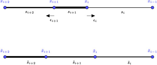
FIGURE 2. Illustration of one step of the positioning algorithm for the case of a strong link bordered by two weak links. The strength of a link is represented by its width.
First we prove that a strong link is not too weakened after one step. Let
and
because the assumption we made on s growth. As a consequence we have:
This inequality confirms that the stronger link did not get weakened enough to have a quality lower that the quality of its neighbors before the move. It means in particular that it is still better than the worse link of the configuration.
For the second part, let
In order to ensure convergence, the algorithm needs to compute for each agent
Overall, the UAVs reach a consensus on link quality because the configuration that maximizes the weakest link is the configuration of equal links, which is unique. Proving the consensus using the dynamics of the system (Ren et al., 2007) would require to write an equation for the evolution of
4.2 Received Signal Strength Indicator Filtering With an Optic Flow-Based Kalman Filter
The algorithm defined in Eq. 12 makes all its decisions on measurements of the link quality, which is measured using the RSSI. Unfortunately, these measurements are noisy and not as reliable as we could hope. In particular, the signal quality is affected by many factors besides the emitter-receiver distance, including the orientation of the UAV, the current motor speed, the radio activity of the other UAVs, beams on the ceiling, and so forth (Khuwaja et al., 2018; McGuire et al., 2019).
We therefore need to filter the RSSI to remove the high frequency noise. Using a simple moving average filter would not be sufficient as the estimation would have too much lag when the agents move towards or apart from each other.
Please note that we are trying here to minimize the time between the measurement (the RSSI changed) and the decision (how to move to improve the situation). We are here neglecting the time lags induced by radio transmission because (1) few messages are exchanged compared to the bandwidth (our Crazyflie UAVs can exchange data up to 1 Mbit), (2) less than 0.25 ms is required to send a packet and get a response, which is fast compared to the dynamics of the whole chain (in our experiments, the drones move at a maximum of 0.3 m/s). To get the best communication performance, we would need to take special care of optimizing the number of packets (in particular, the frequency of packet exchanges) and use a different radio channel for each communication (since each UAV needs to communicate with only 2 other UAVs at most, there is no need to occupy the radio channel).
Our main insights are that (1) we know that the signal quality is likely to decrease when two UAVs move away from each other, and (2) the relative speed of two UAVs can be measured at no computational cost with miniature optic flow sensors (Ruffier et al., 2003). In addition, the miniature Lidars onboard help the UAVs to fly at a nearly constant height, which means that measured optic flow is therefore proportional to the ground speed. Optic flow sensors can also work in low-light conditions (Mafrica et al., 2016). Recent commercial optic flow sensors are derived from optical mouse sensors (e.g., Pixart PMW3901MB) and weight only a few milligrams.
We incorporate this simple model in a 1-D Kalman filter to improve the signal quality estimation. To our knowledge, Kalman filters have never been used to improve the assessment of the signal quality in UAVs, in particular with optic flow sensors. Nevertheless, a few articles used RSSI and Kalman filters for localizing humans or phones by either assuming that the human does not move between two measurements (Bulten et al., 2016) or by combining RSSI and external sensors (Paul and Wan, 2009).
The filter considers that the signal quality decreases linearly with the relative velocity
where
The update of the Kalman filter occurs in two steps. Firstly, the prediction a priori stage updates:
We finally compute the a posteriori estimates with:
with
In both simulated and real tests, we hand-tuned A to minimize estimation noise as well as the delay between the true RSSI and the estimate.
The pseudo-code for the U-chain algorithm, which combines the equalization of the links (Section 4.1) and the Kalman filtering (Section 4.2), is displayed on Algorithm 1. The algorithm essentially gets the RSSI measurements for the previous and next links, filters them, then ask the UAV to either go backward, forward, or stay at the same position, depending on the difference between the two filtered RSSI.
 More precisely, the function
4.3 Exploration With a Chain of UAVs
A straightforward use of Algorithm 1 is to move the first UAV (the head) forward in a tunnel and let the chain self-organize to maintain a stable connection. However, the link quality can drop below
We here assume that the algorithm that equalizes the links converges quickly enough so that links have converged when we make a new UAV take off. Thus, if the link quality between the base and its neighbor is below the threshold, it means that all the links’ qualities are below the threshold. If our assumption of fast convergence for the algorithm holds, the new UAV takes off only if the chain cannot be maintained with a link quality above
If no more relay UAVs are available to take off, the chain still equalizes the links’ qualities but may go under
5 Centering Policy
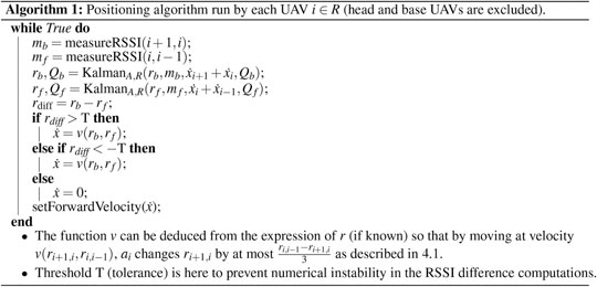
Our UAVs need to autonomously follow the explored tunnel, which can be achieved with a few miniature time-of-flight sensors (we use VL53L1x by ST Electronics). To do so, a reactive controller runs independently from the positioning algorithm to center each drone and follow the corridor turns. This policy uses four diagonal distance sensors to compute both the yaw and the lateral velocities (perpendicular to the wall). More precisely, at each iteration, in parallel with the calculation of
where
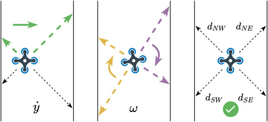
FIGURE 3. Main centering policy (Eq. 20). The quadrotors use the two front distance sensors (
While surprisingly effective, this reactive policy is not always sufficient, in particular for 90 degrees turns. In this situation, the distance of one of the front sensors suddenly increases (e.g.
To mitigate this issue, we calculate the distances ratio of each pair of sensors that sense the left and right sides of the UAVs. If the difference percentage goes beyond a fixed value (40% after calibration tests), we consider that the wall is invalid and ignore it in the centering policy. When this happens, the drone automatically follows the remaining wall at a fixed distance by applying (for example, when the right wall is lost):
with D being a preset distance. This additional policy makes it possible to explore wide rooms by following one side of the room, in addition to center in a tunnel.
6 Experimental Results
6.1 Simulation
6.1.1 Main Assumptions
The internal decision loop of each agent runs at 5 Hz to ensure that the algorithm will be easy to implement in the Crazyflies’ micro-controller.
The UAVs communicate with simulated packet transmissions that are possible only if
The environment is 2-D.
The distance sensors are simulated according to the environment, and the UAVs follow the navigation policy (Section 5).
In these simulations, the communication is considered to be instantaneous.
6.1.2 Signal Propagation Model
We model the RSSI according to models given by Vinogradov et al. (2018). The signal loss estimation is computed as:
with α being the environment’s attenuation factor. When fixed, this expression corresponds to the path loss caused by air attenuation and is the main cause of signal degradation. Then, we include the shadowing phenomenon due to obstacles blocking the line of sight between the communicating agents by varying α, based on the environment. The value varies between 2 and 6 according to the amount of walls the segment between the agents passes through.
Please note that RSSI
In our experiments, we observed that the RSSI was degraded when the path between the two UAVs was passing through their motors (the motors are likely to interfere with the signal). As a consequence, the real RSSI depends on the relative yaw of the UAVs, in addition to the distance. We chose to neglect this effect in the simulation because it is not well documented and might be very specific to the type/position of the antenna of our UAVs (we preferred to use a well-validated model of signal propagation). In future work, this propagation model (Eq. 22) could be extended to take the yaw and the motor positions into account so that the RSSI increases when the direction of the target UAV is at
6.1.3 Results
We firstly checked that the chain successfully converges to stable positions and equalizes the signal quality when n UAVs are already flying in the air. To do so, we positioned the UAVs at random positions in the corridor for three different environments while fixing the position of the head. The results (Figures 4A–C show that the UAVs always converge to the desired solution, in spite of the noise on RSSI measurements. We confirmed this result by randomly generating 30 initial positions for 30 independent runs for each of the three environments: 100% of the runs converged to positions that equalize the RSSI.
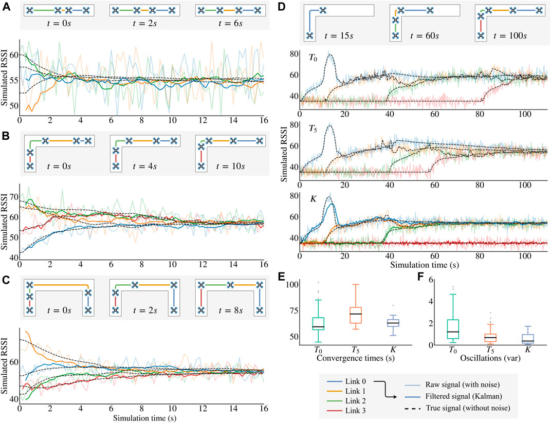
FIGURE 4. Simulation results. For each figure, the true signal (dashed line) is computed using Eq. 22 but without the Gaussian noise (this is unknown to our algorithm); the raw signal (light solid line) is the input of the U-Chain algorithm; and the filtered signal is the result of the Kalman filter used to take the movement decisions. (A)–(C) Convergence of Algorithm 1 in different environments (shown in the corresponding map thumbnails). The UAVs place themselves at “strategic” positions. (D) Comparison between three different signal processing methods:
We then evaluated the usefulness of the Kalman filter when the head drone is moving. We simulated a real exploration by placing all UAVs at the entrance of the corridor and launching the first UAV at the start of the simulation. The head then moves forward at a constant speed (0.2 m per second) before stopping after 50 s of exploration.
When using the raw signal as the entry for Algorithm 1 (Figure 4D, algorithm
A simple way of trying to reduce these oscillations is to introduce a tolerance around the local quality equilibrium of each UAV before applying any movement (algorithm
The Kalman filter improves the system performance on those two factors. The estimation greatly reduces the noise of the signal used in Algorithm 1 which leads to both a short convergence time and less oscillation.
6.2 Real-World Experiment
We designed a circuit that resembles a real corridor or pipe and respects the monotonic propagation constraint. The walls are made of thin paper boards for installation simplicity, and therefore do not block the signals in any way (to respect the monotonic propagation constraint, we therefore had to choose the shape of the tunnel carefully). However, these walls prevent the UAVs from taking the shortest path, which means that the signal quality follows a complex non-linear function along the tunnel. While this experiment does not fully capture an underground scenario, it makes it possible to validate the centering policy, the take-off decisions, and the overall maintenance of the chain.
The micro UAVs used in our experiments are off-the-shelf commercial micro drones (Crazyflie 2.1 by Bitcraze, Figure 5) with two sensor add-ons (called “decks”). The first deck provides four time-of-flight distance sensors that detect obstacles up to 2 m (the detection angle is 27 degrees), which are used by the centering policy (Section 5). The second deck provides a fifth time-of-flight distance sensor that points downward, which is used to stabilize the UAV vertically. The same deck embeds an optical flow sensor, which helps stabilizing the UAV (by avoiding to drift) and provides the data for the ground speed estimate used in our algorithm (Section 4).
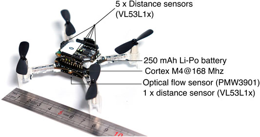
FIGURE 5. The Crazyflie 2.1 quadrotor (Giernacki et al., 2017). The quadrotor used in the real experiments (Figure 6) is about 12 cm by 12 cm (including the propellers). We use the “flow deck”, which adds an optical flow sensor and a distance sensor (pointing towards the ground) and the “Multi-ranger deck”, which provides 5 distance sensors (time of flight).
We added drone-to-drone (peer to peer) communication, as the original firmware only supported packet transmissions between the micro UAVs and a computer. The source code of the upgraded firmware code is available online (https://github.com/resibots/crazyflie-firmware/, branch “cavemod”).
In the experiments, all UAVs are initially positioned at the start of the corridor (Figures 6A) and are ready to take off when needed, except the last drone, which acts as a fixed base station. We launch the first UAV and manually control it with the keyboard keys (the pilot can only go forward or backward—the actual stabilization and centering is autonomous). The other UAVs then apply all presented algorithms in this paper to launch and relay the signal when needed.
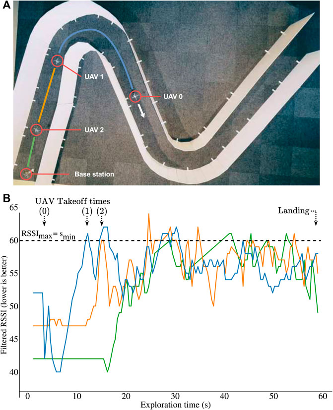
FIGURE 6. Experiments with 3 Crazyflie 2.1 quadrotors and a base station. The robots use an optic flow sensor and 5 time-of-flight sensors (altitude and centering). They communicate with a custom peer to peer protocol. (A) Environment used for the experiments. (B) Qualities of the radio links (RSSI) during exploration in the real experiment of panel A: after a few seconds, the quality of all the links are equal and below the threshold (
Overall, the system performs similarly to the simulations (Figures 6B): all relays take off when the last active link reaches the fixed limit, and the UAVs successfully equalize the 3 links’ qualities until the end of the exploration. A video is available as Supplementary Material. At the end of the experiment, the robots are not equally spaced, which is expected because the algorithm equalizes the quality of the links and not the distances. This is an important feature because the link quality is what matters in this experiment, and they typically depend on many factors (including the materials and the presence of turns in the tunnel). In addition, the robots never fully stop (as seen on the video) because the signal quality, even filtered, is still imperfect.
7 Discussion
By combining a reactive positioning algorithm with a Kalman filter, the U-Chain algorithm can coordinate a chain of UAVs in a tunnel to maintain a high-quality connection while being light enough to be embedded on miniature UAVs. Since only the signal’s qualities are considered, the chain of UAVs adapts to any unexpected signal propagation, turns, radio perturbations, etc. While we did not consider intersections in this work, it is straightforward to store and transmit the direction choice made by the pilot who is controlling the head UAV, provided that a crude approximate of the position x in the tunnel is available (so that the following UAV can take the same decision).
The main hypothesis of the present work is that the quality of the signal decreases monotonically with the distance between an emitter and a receiver. This hypothesis is reasonable in an underground environment in which the signals never pass through walls: the signal is very unlikely to get better when the UAVs progress into a tunnel. However, this is often not the case in more general indoor environments, and in particular in modern buildings in which the radio signal can often pass through walls: in these cases, the signal can improve if there exists a path through the walls that is shorter than the physical path available (e.g., a door or a corridor). Future work will attempt to relax the monotony hypothesis while ensuring the convergence properties, in particular when the head UAV is moving.
The current algorithm assumes that the UAVs are moving in a single tunnel, without any branching. A natural extension is to modify it so that it can be used in more complex underground structures. In that situation, our vision is that the pilot of the head drone (or a exploration algorithm) has to decide which branch to follow, and the chain has to be maintained. If there are only two choices (left and right), then the centering policy needs to be slightly modified to make it possible to select which wall to follow (instead of centering between two walls or invalidating one of the walls in a big room); this modification is straightforward. The pilot then will be able to select which wall to follow, which will correspond to selecting the corridor. The positioning (forward or backward) algorithm should need no modification; however, the UAVs of the chain will also need to select which wall to follow when they reach an intersection. This would require them to know (1) the decision taken by the head UAV, which can be to transmitted by radio, and (2) their approximate position or a way to identify an intersection, which is challenging to obtain with a pure signal-based system. Solving this challenge might require the UAV to embed a place recognition system, a visual odometry system, or a SLAM system. If there are more than two branches from which to choose, then the pilot will need to drive the head drone to the branch he/she wants to explore and this decision needs to be replicated by the other drones of the chain, with an approach that needs to be determined.
The reported experiments, both in simulation and in reality, used “clean” (flat) walls for simplicity. However, our preliminary experiments with more rugged walls show that our centering policy is overall robust to deal with more complex environments. First, the centering policy is purely reactive, therefore ruggedness can only introduce small oscillations in yaw and translation. Nevertheless, the laser sensors that we use are designed to have a large field of view (27 degrees for the VL53L1X), which means that they tend to average the distances over a large surface (about 22 cm for a 50 cm distance). In other words, the surface is always smooth for the sensor. Second, the quality of the distance measurements is influenced by the light absorption of the material. However, if the material is the same on both walls (which is likely in a corridor), then the behavior will not change because the policy only computes relative differences (it equalizes the values); if they are different, then the UAV will not be centered anymore, but this will not change the overall behavior of the chain (what matters it that the UAV does not hit the wall). In our experience, the VL53L1X sensors are reliable for the vast majority of surfaces that we tested. In addition, complex, irregular radio absorption are invisible to the positioning algorithm, because it only looks at the empirical signal quality. As a consequence, we do not expect any issue with irregular absorption or diverse materials.
One the main limitations of tiny UAVs like the Crazyflie is their limited energetic autonomy (usually 5–15 min). An interesting research avenue is to extend our U-Chain algorithm to maintain the chain indefinitely by replacing UAVs with a low battery when needed; this could be useful to observe a place for a long time, or, for example, for keeping a radio link with a human (e.g., a stranded survivor of a mine collapse). A potential algorithm would be to continuously sort the UAVs so that the UAV with the lowest battery level would always be the closest to the base station and can be swapped with a fresh UAV when needed. This could be implemented in a distributed fashion by applying the “bubble sort” strategy: each UAV compares its battery level to the one of the previous one in the chain, and it swaps its position if its battery level is significantly lower. One of the main challenges of such an approach would be to implement the swap in a narrow tunnel without collision; another one is to maintain the connectivity during the swap, which will require substantial modifications of the positioning algorithm, as well as a temporary contractions of the chain and/or the addition of UAVs to compensate.
Data Availability Statement
The original contributions presented in the study are included in the article/Supplementary Material, further inquiries can be directed to the corresponding author.
Author Contributions
PL, EN, and J-BM designed the study. PL designed the algorithms and performed the experiments. VT wrote the proofs. FR contributed the parts related to optic flow. PL, VT, FR, EN and J-BM wrote the paper.
Funding
This work received funding from the European Research Council (ERC) under the European Union's Horizon 2020 research and innovation programme (GA No. 637972, project “ResiBots”), the DGA-Inria project "U-Drone", and the ANR/DGA ASTRID project Proxilearn (ANR-19-ASTR-0009).
Conflict of Interest
The authors declare that the research was conducted in the absence of any commercial or financial relationships that could be construed as a potential conflict of interest.
Supplementary Material
The Supplementary Material for this article can be found online at: https://www.frontiersin.org/articles/10.3389/frobt.2021.614206/full#supplementary-material.
References
Akyildiz, I. F., Sun, Z., and Vuran, M. C. (2009). Signal propagation techniques for wireless underground communication networks. Phys. Commun. 2, 167–183. doi:10.1016/j.phycom.2009.03.004
Amigoni, F., Banfi, J., and Basilico, N. (2017). Multirobot exploration of communication-restricted environments: a survey. IEEE Intell. Syst. 32, 48–57. doi:10.1109/MIS.2017.4531226
Bulten, W., Van Rossum, A. C., and Haselager, W. F. G. (2016). “Human slam, indoor localisation of devices and users,” in First international conference on internet-of-things design and implementation (IoTDI), Berlin, Germany, April 6, 2016 (New York, United States: IEEE), 211–222. doi:10.1109/IoTDI.2015.19
Cesare, K., Skeele, R., Yoo, S.-H., Zhang, Y., and Hollinger, G. (2015). “Multi-UAV exploration with limited communication and battery,” in International Conference on Robotics and Automation (ICRA), Washington, United States, May 26–30, 2015 (New York, United States: IEEE), 2230–2235.
Dorigo, M., Floreano, D., Mondada, F., Nolfi, S., Baaboura, T., Birattari, M., et al. (2013). Swarmanoid: a novel concept for the study of heterogeneous robotic swarms. IEEE Robot. Automat. Mag. 20, 60–71. doi:10.1109/mra.2013.2252996
Freire, G., and Cota, R. (2017). “Capture of images in inaccessible areas in an underground mine using an unmanned aerial vehicle,” in Proceedings of the first international conference on underground mining technology, Sudbury, Canada, October 11–13, 2017. doi:10.36487/acg_rep/1710_54_freire
Giernacki, W., Skwierczyński, M., Witwicki, W., Wroński, P., and Kozierski, P. (2017). “Crazyflie 2.0 quadrotor as a platform for research and education in robotics and control engineering,” in 22nd international conference on methods and models in automation and robotics (MMAR), Międzyzdroje, Poland, Augest 28–31, 2017 (New York, United States: IEEE).
Hauert, S., Zufferey, J.-C., and Floreano, D. (2009). Evolved swarming without positioning information: an application in aerial communication relay. Auton. Robot 26, 21–32. doi:10.1007/s10514-008-9104-9
Hsieh, M. A., Cowley, A., Kumar, V., and Taylor, C. J. (2008). Maintaining network connectivity and performance in robot teams. J. Field Robot. 25, 111–131. doi:10.1002/rob.20221
Jaffe, J. (1981). Bottleneck flow control. IEEE Trans. Commun. 29, 954–962. doi:10.1109/tcom.1981.1095081
Jones, E., Sofonia, J., Canales, C., Hrabar, S., and Kendoul, F. (2019). “Advances and applications for automated drones in underground mining operations,” in Proceedings of the ninth international conference on deep and high stress mining, South Africa, June 29, 2019, 323–334.
Khuwaja, A. A., Chen, Y., Zhao, N., Alouini, M.-S., and Dobbins, P. (2018). A survey of channel modeling for UAV communications. IEEE Commun. Surv. Tutor. 20, 2804–2821. doi:10.1109/COMST.2018.2856587
Mafrica, S., Servel, A., and Ruffier, F. (2016). “Optic-flow based car-like robot operating in a 5-decade light level range,” in International conference on robotics and automation (ICRA), Stockholm, Sweden, May 16–21, 2016 (New York, United States: IEEE), 5568–5575.
Mansouri, S. S., Castaño, M., Kanellakis, C., and Nikolakopoulos, G. (2019). “Autonomous MAV navigation in underground mines using darkness contours detection,” in International conference on computer vision systems, Thessaloniki, Greece, September 23–25, 2019, 164–174.
McGuire, K., De Wagter, C., Tuyls, K., Kappen, H., and de Croon, G. (2019). Minimal navigation solution for a swarm of tiny flying robots to explore an unknown environment. Sci. Robot. 4, eaaw9710. doi:10.1126/scirobotics.aaw9710
Morris, A., Ferguson, D., Omohundro, Z., Bradley, D., Silver, D., Baker, C., et al. (2006). Recent developments in subterranean robotics. J. Field Robot. 23, 35–57. doi:10.1002/rob.20106
Nestmeyer, T., Giordano, P. R., Bülthoff, H. H., and Franchi, A. (2017). Decentralized simultaneous multi-target exploration using a connected network of multiple robots. Autonom. Rob. 41 (4) , 989–1011. doi:10.1007/s10514-016-9578-9
Paul, A. S., and Wan, E. A. (2009). RSSI-based indoor localization and tracking using sigma-point kalman smoothers. IEEE J. Sel. Top. Signal Process. 3, 860–873. doi:10.1109/jstsp.2009.2032309
Pei, Y., Mutka, M. W., and Xi, N. (2010). “Coordinated multi-robot real-time exploration with connectivity and bandwidth awareness,” in International conference on robotics and automation (ICRA), Anchorage, Alaska, May 8–10, 2010 (New York, United States: IEEE).
Preston, R. P., and Roy, J. (2017). “Use of unmanned aerial vehicles to supplement conventional investigation methods for underground open void stability and mitigation,” in Proceedings of the first international conference on underground mining technology, Sudbury, Canada, October 11–13, 2017, doi:10.36487/acg_rep/1710_49_preston
Ren, W., Beard, R. W., and Atkins, E. M. (2007). Information consensus in multivehicle cooperative control. IEEE Control. Syst. Mag. 27, 71–82. doi:10.1109/MCS.2007.338264
Rizzo, C., Tardioli, D., Sicignano, D., Riazuelo, L., Villarroel, J. L., and Montano, L. (2013). Signal-based deployment planning for robot teams in tunnel-like fading environments. Int. J. Robot. Res. 32, 1381–1397. doi:10.1177/0278364913501779
Rogers, J. G., Sherrill, R. E., Schang, A., Meadows, S. L., Cox, E. P., Byrne, B., et al. (2017). “Distributed subterranean exploration and mapping with teams of UAVs,” in Editors T. Pham, and A. K. Michael Ground/air multisensor interoperability, integration, and networking for persistent ISR VIII, California, United States, April 10–13, 2017 (Washington, United States: SPIE). doi:10.1117/12.2266316
Ruffier, F., Viollet, S., Amic, S., and Franceschini, N. (2003). “Bio-inspired optical flow circuits for the visual guidance of micro air vehicles,” in Proceedings of the 2003 international symposium on circuits and systems (ISCAS’03), Bangkok, Thailand, May 25–28, 2003 (New York, United States: IEEE). doi:10.1117/12.498193
Stump, E., Michael, N., Kumar, V., and Isler, V. (2011). “Visibility-based deployment of robot formations for communication maintenance,” in International conference on robotics and automation (ICRA), Shanghai, China, May 09–13, 2011 (Piscataway,NJ: IEEE), 4498–4505.
Thrun, S., Thayer, S., Whittaker, W., Baker, C., Burgard, W., Ferguson, D., et al. (2004). Autonomous exploration and mapping of abandoned mines. IEEE Robot. Automat. Mag. 11, 79–91. doi:10.1109/mra.2004.1371614
Keywords: UAV (drone), RSSI (received signal strength indication), underground, subterranean, radio signal
Citation: Laclau P, Tempez V, Ruffier F, Natalizio E and Mouret J-B (2021) Signal-Based Self-Organization of a Chain of UAVs for Subterranean Exploration. Front. Robot. AI 8:614206. doi: 10.3389/frobt.2021.614206
Received: 05 October 2020; Accepted: 08 February 2021;
Published: 23 April 2021.
Edited by:
George C. Karras, University of Thessaly, GreeceReviewed by:
Heiko Hamann, University of Lübeck, GermanyChristos Verginis, University of Texas at Austin, United States
Copyright © 2021 Laclau, Tempez, Ruffier, Natalizio and Mouret. This is an open-access article distributed under the terms of the Creative Commons Attribution License (CC BY). The use, distribution or reproduction in other forums is permitted, provided the original author(s) and the copyright owner(s) are credited and that the original publication in this journal is cited, in accordance with accepted academic practice. No use, distribution or reproduction is permitted which does not comply with these terms.
*Correspondence: Jean-Baptiste Mouret, jean-baptiste.mouret@inria.fr