Encouraging Volitional Pedaling in Functional Electrical Stimulation-Assisted Cycling Using Barrier Functions
 Axton Isaly
 Brendon C. Allen1
  Warren E. Dixon
- 1Department of Mechanical and Aerospace Engineering, University of Florida, Gainesville, FL, United States
- 2Department of Electrical and Computer Engineering, University of California, Santa Cruz, Santa Cruz, CA, United States
Stationary motorized cycling assisted by functional electrical stimulation (FES) is a popular therapy for people with movement impairments. Maximizing volitional contributions from the rider of the cycle can lead to long-term benefits like increased muscular strength and cardiovascular endurance. This paper develops a combined motor and FES control system that tasks the rider with maintaining their cadence near a target point using their own volition, while assistance or resistance is applied gradually as their cadence approaches the lower or upper boundary, respectively, of a user-defined safe range. Safety-ensuring barrier functions are used to guarantee that the rider’s cadence is constrained to the safe range, while minimal assistance is provided within the range to maximize effort by the rider. FES stimulation is applied before electric motor assistance to further increase power output from the rider. To account for uncertain dynamics, barrier function methods are combined with robust control tools from Lyapunov theory to develop controllers that guarantee safety in the worst-case. Because of the intermittent nature of FES stimulation, the closed-loop system is modeled as a hybrid system to certify that the set of states for which the cadence is in the safe range is asymptotically stable. The performance of the developed control method is demonstrated experimentally on five participants. The barrier function controller constrained the riders’ cadence in a range of 50 ± 5 RPM with an average cadence standard deviation of 1.4 RPM for a protocol where cadence with minimal variance was prioritized and used minimal assistance from the motor (4.1% of trial duration) in a separate protocol where power output from the rider was prioritized.
1 Introduction
Stationary cycling assisted by functional electrical stimulation (FES) can lead to long-term benefits for people with movement impairments due to neurological conditions such as stroke, spinal cord injury, traumatic brain injury, cerebral palsy, multiple sclerosis, and others Johnston et al. (2008); Ferrante et al. (2008); Hooker et al. (1992); Janssen et al. (2008); Trevisi et al. (2012). Individuals with neurological conditions can exhibit varying degrees of muscle control. For people with little to no volitional control, the FES cycling therapy must be supported by an electric motor, which provides additional torque about the pedal crank to maintain a beneficial cadence, as in studies such as Cousin et al. (2020); Hooker et al. (1992); Bellman et al. (2017); Duenas et al. (2020); Trevisi et al. (2012). When possible, electric motor support should be minimized in lieu of torque produced by the rider’s muscles via either FES or their own volition, which leads to higher intensity training by increasing the rider’s heart rate and oxygen uptake Hooker et al. (1992). Higher intensity training is a key factor in attaining long-term outcomes like increased muscular strength, cardiovascular endurance, bone mineral density, and caloric consumption Ouellette et al. (2004); MacKay-Lyons and Makrides (2002); Mohr et al. (1997). In the rehabilitation literature outside of cycling, various assist-as-needed approaches such as Asl et al. (2020); Dao and Yamamoto (2018); Pehlivan et al. (2015); Ding et al. (2014) encourage volitional contributions from the user. Relatively few works have investigated FES- and motor-assisted cycling programs where the primary objective is to encourage volitional contributions Harrington et al. (2012); Rouse et al. (2020); Johnston and Wainwright (2011). The objective of this work is to design controllers for both the electric motor and FES stimulation that facilitate volitional cycling by minimizing machine assistance while ensuring that the rider’s cadence is constrained to a user-defined range.
The kinematics of the rider’s legs during stationary cycling are such that applying FES to their muscles produces non-negligible torque only in certain regions of the crank cycle. To maximize torque production, stimulation patterns often feature discontinuous jumps triggered as a function of the crank angle by discrete logic variables. The interaction of the resulting continuous-time and discrete dynamics results in a hybrid control system. Barrier functions, or control barrier functions (CBF), can be used to design controllers for hybrid systems that ensure safety by rendering sets of states either forward invariant or asymptotically stable Ames et al. (2019); Maghenem and Sanfelice (2021); Glotfelter et al. (2017). This technique builds on ideas from the theory of control Lyapunov functions (CLF). CLFs are used to enforce particular constraints on the control input that result in a decrease in a Lyapunov function for states outside of the safe set Freeman and Kokotovic (1996); Sanfelice (2013). However, CLF-based approaches have typically not provided constructive methods for designing the control input at states in the safe set. Recent developments regarding CBFs have filled this gap by providing a systematic approach for extending the input constraints onto the safe set in a way that reduces the control effort on the interior of the set Ames et al. (2016). A popular approach for implementing CLF- or CBF-induced input constraints is with pointwise optimal control laws which, for certain classes of dynamics, take the form of quadratic programs (QP). Compared to past assist-as-needed control schemes, which have used methods such as deadzone functions Asl et al. (2020) or impedance control Ding et al. (2014), barrier functions can constrain the state within a broader class of safe sets. Moreover, the cost function in the accompanying pointwise optimal control law is customizable, leading to a range of possible controllers. Our preliminary work in Isaly et al. (2020) integrated zeroing CBFs with robust control tools from Lyapunov theory to synthesize a QP for an uncertain, continuous-time, motor-only cycling system. The controller in Isaly et al. (2020) constrains the rider’s cadence within a user-defined range while encouraging volitional pedaling by using minimal motor control effort. However, the more complex case where the rider is also stimulated by FES was not considered.
In this work, we extend the development of Isaly et al. (2020) to account for the hybrid dynamics introduced by adding FES stimulation. The resulting controller applies assistance based on the rider’s performance. FES assistance is only applied when the cadence cannot be maintained at a target value through volitional effort alone. Similarly, assistance from the electric motor is applied only when the combined FES and volitional efforts are insufficient. The controller accommodates a broad range of functional impairments and volitional ability by featuring customizable parameters, including nominal control inputs and tunable width of the safe range. Moreover, the rider’s safety is assured because the electric motor constrains the rider’s cadence to a uniformly globally asymptotically stable set through a continuous feedback controller. The continuity of the motor control law is an improvement upon the breakthrough strategy in Rouse et al. (2020) for encouraging volitional pedaling. In that work, no control effort was applied within a user-defined region, while the electric motor and FES were turned on discontinuously at the boundary of the region. Outside the region, assistive control effort switched discretely between FES and electric motor assistance to ensure that the electric motor did not prevent FES from inducing power output by the rider. In contrast, we decouple the motor and FES controllers and use more sophisticated design tools to develop a motor control law that is a continuous function of the cadence tracking error. The result is more comfortable training for the rider, while the staggered application of FES before motor effort still allows power output from the rider to be prioritized.
Experimental trials were performed on five able-bodied participants to demonstrate the effectiveness and versatility of the developed control system. The barrier function controller was shown to effectively constrain the cadence to a range of 50 ± 5 RPM for all but a negligible amount of time, and to outperform the controller in Rouse et al. (2020) and uncontrolled volitional pedaling for a protocol where minimal cadence variation was prioritized. The barrier function controller had a lower cadence standard deviation (Avg. 1.4 RPM) and constrained the cadence to a smaller range relative to the comparison cases, but generally produced more assistive torque from the motor than the controller in Rouse et al. (2020). To show how motor assistance can be reduced to prioritize power output from the rider, an alternative protocol was designed where the customizable parameters were configured with a wider safe range and a nominal amount of resistance from the motor. In the alternative trial, the motor was producing assistive torque for only 4.1% of the entire trial duration.
2 Dynamic Model
2.1 Hybrid Systems
The development in this work is based on the hybrid systems framework described in Goebel et al. (2012). A hybrid system
When the state is in the flow set
Remark 1. Previous results (cf. Rouse et al. (2020); Bellman et al. (2017); Rouse et al. (2021)) have analyzed the dynamic model in the subsequent section using switched-systems tools. The decision to use a hybrid model here was motivated by the fact that forward invariance via barrier functions is not well characterized for switched systems, nor are many results available regarding the stability of noncompact sets. Hybrid systems can model broad classes of switched systems Goebel et al. (2012, Section 2.4).
2.2 Open-Loop Dynamics
Analogous to Eq. 1, one can also consider hybrid systems with inputs Sanfelice (2013). We use such a system to describe the control design but present our stability analysis in terms of a closed-loop system with the form in Eq. 1. The open-loop cycle-rider system is modeled as a continuous-time system
and flow set
where
where ce > 0 is the known electric motor control constant relating input current to output torque. The torque generated from FES inputs to the rider’s muscles
where the continuous functions
The following properties of the cycle-rider system in Eq. 2 are derived from a detailed dynamic model, as discussed in Bellman et al. (2017).
Property 1. The inertial term is upper- and lower-bounded as
Property 2. The centripetal-Coriolis parameter is upper-bounded as
Property 3. The torque generated by gravity is upper-bounded as
Property 4. The torque generated by the rider’s viscoelastic tissues is upper-bounded as
Property 5. The torque due to viscous damping is upper-bounded as
Property 6. The torques generated by system disturbances are bounded so that
Property 7. Due to physical limitations of the rider, the volitional muscle torque is bounded so that
Property 8. For each
Property 9. The set-valued mapping
3 Control Design
Figure 1 shows a schematic of the staggered control regions for the developed system. The volitional range is a region near the setpoint z2d where the control inputs are zero, thereby forcing the rider to pedal on their own volition (optionally, a nominal amount of assistance or resistance can be provided based on the needs of the rider). When the cadence is slower than z2d, FES assistance is provided before assistance from the electric motor. When the cadence is faster than the setpoint, only the electric motor is used because creating resistive torque with FES by stimulating antagonistic muscles is undesirable. The rider or clinician can modify the amount of control effort provided and the size of the controlled regions using parameters adjusted for the specific individual.
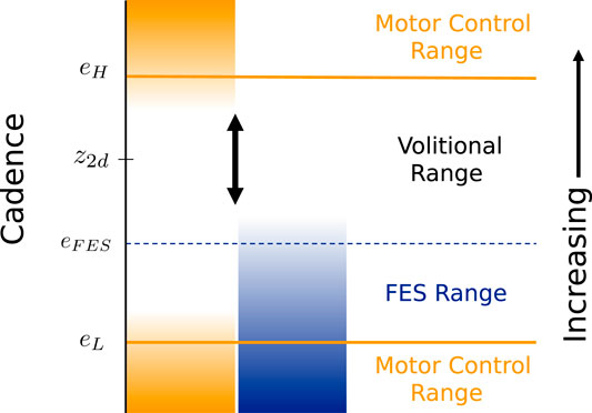
FIGURE 1. Illustration of the regions of applied control effort as a function of cadence. No control effort is applied in the volitional range near the setpoint z2d. The electric motor control input increases when the cadence approaches the boundaries defined by eH and eL, and the FES control signal does the same near eFES. The size of each region is adjustable. The cadence range between eH and eL is rendered asymptotically stable by the developed control system.
3.1 Control Objective
To formalize the control objective, we define the tracking error e as the deviation of the cadence state z2 from a constant setpoint z2d > 0,3
The primary control objective is to guarantee a safe and effective therapy by constraining the rider’s cadence to the safe set
The goal is to synthesize, in a systematic way, controllers that render a given set of states uniformly globally asymptotically stable (UGAS) while using the minimum required effort inside the set of interest.4 Combining ideas from CLF theory with recent developments regarding CBFs, this task is accomplished by using a QP to enforce a constraint on the control input that is induced by a candidate barrier function. The following lemma, presented in a more generic form than in our preliminary work in Isaly et al. (2020), gives conditions under which a QP-based control law with a single constraint is feasible and locally Lipschitz continuous. The closed-form solution of the QP in the absence of a nominal controller (but including the case of multiple control inputs) has also been presented in Freeman and Kokotovic (1996, Section 4.2.2) and was developed in detail in Xu et al. (2015), Thm. 8. In those works, the feasibility condition was guaranteed by assuming the existence of a CLF or CBF, respectively. Because the addition of a nominal controller is a minor extension of the available literature, we do not present a proof of the result. Lemma 1 applies to the control laws developed in the subsequent sections.
Lemma 1. Let the functions
Then the set-valued mapping
is locally Lipschitz on
Note that there is no division by zero in Eq. 8 since Eq. 6 implies that
3.2 Motor Control Design
In this section, the electric motor control input is designed to ensure that the safe set
where
Equivalent to the original definition, we have
While barrier functions are typically associated with forward invariance, they are naturally extensible to enforcing the stronger property of asymptotic stability. Asymptotic stability is beneficial for real-world applications since it guarantees robustness to perturbations from the safe set. For continuous-time systems, the stronger asymptotic stability condition is embodied in the definition of a zeroing CBF (ZCBF) Xu et al. (2015). Inspired by the ZCBF approach in our preliminary work in Isaly et al. (2020) and the work regarding CLFs for hybrid systems in Sanfelice (2013), we constrain the control input according to the so-called regulation map
where
and kb1 > 0 is a control gain. In the stability analysis of Section 4, we show that selecting a continuous controller from
Remark 2. The definition of a ZCBF requires that
The regulation map in Eq. 10 is not directly useful for design purposes because uncertainty in the dynamics prevents computation of the inequality (i.e., constraint) used to define
The product
for each
In Eq. 13, the function τu depends on the motor control input ue and the muscle control inputs uM. Because the value of the subsequently designed muscle control input will jump at discrete instances, it is desirable to decouple the motor input from the muscle input to ensure the continuity of the motor controller. A continuous motor controller will be more predictable and comfortable for the rider. Using Property 8, there exists a constant cM > 0 such that
for all
Selecting5
implies that
for all
The following result summarizes the preceding development and explains the utility of
Proposition 1. Assume k1, k2, and k3 satisfy the gain conditions in Eq. 16 and z2d > 0. Then, for any
The constraint used to define
where
Since the parameters in Eq. 20 are user-selected, they can be designed to ensure the inequality holds. Given this gain condition, the controller has the properties described in Lemma 1, in particular, it is continuous. The closed-form solution to Eq. 19 can be developed from Eq. 8. The controller is implementable in either form but the closed-form solution is computationally faster and does not require an optimization package. Note that the piecewise linear function
Remark 3. During the experiments in Section 5, we investigated constant nominal controllers
3.3 Functional Electrical Stimulation Design
To describe the FES control input, we define a concatenated state vector
where
where
As discussed in Section 3.1, it is generally not possible to maintain the cadence in the set
where
and
When e = 0, the feasibility condition (6) in Lemma 1 requires that
under which the function
When the nominal controller in Eq. 23 is set to
4 Stability Analysis
We model the closed-loop system as a hybrid system
The hybrid system
where
Jumps occur when the timer state τ grows to τD,
The jump map
The set-valued case in Eq. 25 indicates that if τ reaches τD when the state z1 is precisely on the boundary of
Remark 4. The gain conditions in Eqs. 20, 24 must be satisfied because they lead to the feasibility of the QP-based controllers. The conditions are restated here for emphasis:
Theorem 1. Consider the closed-loop cycle-rider system
Proof. Since Be in Eq. 9 is such that
for all x ∈ C and each
for all x ∈ D and each
The conditions in Eqs. 26, 27, and the fact that
To conclude that
To eliminate the possibility that maximal solutions escape in finite time by flowing, we first let ϕ be a solution to
5 Experimental Results
The developed barrier function controller was tested on five participants and compared against uncontrolled volitional pedaling and the 3-Mode (3M) controller developed in Rouse et al. (2020), Section 3. As described in Section 1, the main idea behind the 3M controller is to create a region near the setpoint z2d where no assistance is provided, with discontinuous control effort being applied on the boundary of the region. In contrast to the barrier function controller, the electric motor controller for the 3M controller is coupled with FES stimulation via the angular position state z1, so that the motor is inactive whenever FES is active, and vice versa.
The barrier function controller can be configured for various purposes based on the needs of the rider. Generally, there is a trade-off where smaller user-defined cadence ranges lead to greater applied control effort. Protocol A was designed to investigate whether the controller can reduce the variance in the rider’s cadence by constraining their cadence within a small range. Such a trial provides a point of comparison with the 3M controller and uncontrolled volitional pedaling and generates data where the controller is more active. Protocol B was designed to show how assistance from the motor can be reduced by selecting a wider safe range, thereby encouraging more volitional contributions from the rider. In fact, Protocol B featured a nominal amount of resistance from the motor, making the program more challenging and requiring additional power output from the rider.
Due to COVID-19 related difficulties in scheduling participants with neurological conditions, the trials for this demonstration were done with able-bodied subjects. Each participant gave written informed consent approved by the University of Florida Institutional Review Board (IRB201600881). Participants 1-3 were male, participants 4 and 5 were female, and all ranged in age from 21–29 years old.
5.1 Testbed
The experimental testbed consisted of a stationary recumbent tricycle (TerraTrike Rover) with a 250 W, 24 V motor (Unite Motor Co.) coupled to the drive chain as described in Bellman et al. (2017), Section 5.1. To measure position and cadence, an optical encoder with an angular resolution of 20,000 pulses per revolution (US Digital H1) was mounted to the crank using spur gears. The motor was actuated using an Advanced Motion Controls10 motor driver and current-controlled power supply. Stimulation was delivered to the rider’s quadricep, hamstring, and gluteal muscle groups via self-adhesive electrodes provided compliments of Axelgaard Manufacturing Co., Ltd. A current-controlled stimulator (Hasomed Rehastim) delivered symmetric, rectangular, and bi-phasic pulses at fixed amplitude (90 mA, 80 mA, and 70 mA for the quadriceps, hamstrings, and gluteals, respectively) and frequency (60 Hz), while the pulse width was used as the control input. A desktop computer running real-time control software (QUARC integrated with Simulink) was used to interface the controllers and hardware through a data acquisition board (Quanser QPIDe) with a sampling rate of 1,000 Hz. For additional safety, an emergency stop switch was mounted on the cycle to allow the participant to end the experiment if required.
5.2 Procedure
The primary testing procedure (Protocol A) consisted of 180-s tests for each of the three configurations (barrier function, 3M, and volition-only) under consideration. The volitional pedaling trial was always first, followed by a random selection of either the barrier function or 3M controller. The riders were asked to track a setpoint of z2d = 50 RPM. The safe set boundary for the barrier function controller was encoded by eL = − 5 RPM and eH = 5 RPM, while eFES = − 3 RPM. The inactive region for the 3M controller was 48–52 RPM, which is comparable to the range 50–55 RPM that was used for the experiments in Rouse et al. (2020). The rider was shown a live plot of their cadence featuring a visible indication of the setpoint. Due to differences between the barrier function and 3M controllers, participants were not shown the boundaries of the safe set11.
The 180 s tests started with a 20 s ramp-up phase where the rider sat passively while the motor brought their cadence to the setpoint. To ensure that the presented data represented steady-state operation, the ramp-up and an additional 20 s after it was excluded from each dataset in post-processing. For each configuration, there was a separate warm-up run before the recorded session so the rider could become accustomed to the controller.
Measurements of the position of the rider’s legs with respect to the cycle were used to determine the regions of effective torque transfer
Additional trials were conducted to highlight unique aspects of the barrier function controller, which were performed with only one participant. Protocol B was designed to prioritize power output from the rider over cadence tracking. For this alternative trial, the width of the safe range was larger, with eL = − 12 RPM, eH = 10 RPM, and eFES = − 6 RPM. Because the rider (Participant #2) was able-bodied, we chose to make the program more challenging by adding nominal controllers with
5.3 Results
Table 1 shows relevant statistics for the three configurations tested for Protocol A, including the average and standard deviation of the cadence, percentage of the trial duration for which FES was actively stimulating, and time spent outside of the safe set

TABLE 1. Protocol A: Cycling metrics during steady-state operation (140 second trial).
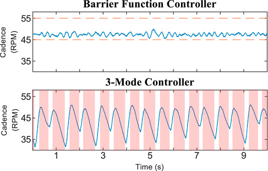
FIGURE 2. Cadence and motor control input for 30-s segments of the trials using Protocol A. Random selection was used to choose which participants and time periods were plotted. The time axis is offset to zero for readability. The dashed orange line in the barrier function cadence plot indicates the boundary of the safe set
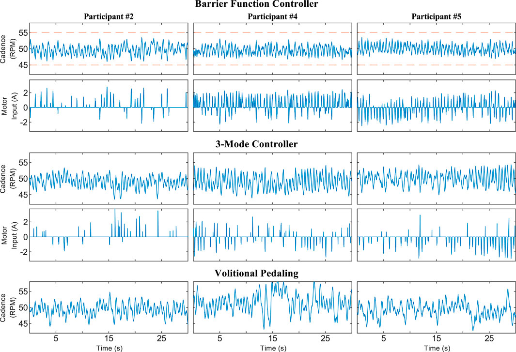
FIGURE 3. Zoomed view of a 5-s time period during a trial using Protocol A showing the cadence, motor control input, and stimulation pulse-width (PW) for Participant 5. Random selection was used to choose which participant and time period were plotted. The time axis is offset to zero for readability. A pulse-width feedforward term of 10 μs was used to facilitate stimulation. The stimulation does not significantly affect the participant at or below 10 μs.
Figure 4 shows the trials using Protocol C, where Participant #1 provided no volitional effort. The barrier function controller was still able to keep the rider’s cadence within the safe set, while the 3M controller caused large oscillations; the mean ± SD cadence for the 3M controller was 43.74 ± 4.94 RPM. The cadence dropped as low as 31.54 RPM during the 3M trial because the electric motor was inactive in the shaded regions of Figure 4. When the motor was next switched on, it compensated using control action with a maximum magnitude of 17.74 A, which was relatively large compared to a maximum of 8.13 A for the 3M controller during the Protocol A trials.
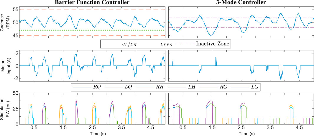
FIGURE 4. Cadence from a trial using Protocol C, where Participant #1 was asked to provide no volitional effort. The 3M controller was problematic in this scenario due to switching between FES and motor control. The shaded red regions in the 3-Mode plot correspond to times when the electric motor was switched off.
The results for Protocol B, where there were nonzero nominal controllers and a wider safe range, are displayed in Figure 5 and Table 2. There was high utilization of the electric motor to produce resistive torque, but low assistive torque production. The assistive torque was smaller than the Protocol A average and, in particular, was smaller than Participant #2’s results. The resistive torque was large and FES was more active for Protocol B due to the design of the nominal controllers. The electric motor deviated from its nominal value for only 7.7% of the trial duration and was providing assistance for 4.1% of the trial. The cadence standard deviation was higher than uncontrolled volitional pedaling, which was most likely because the control inputs were actively pushing the rider away from the setpoint. The assistive torque from the barrier function controller in Protocol B was comparable to the 3M controller in the Protocol A trials.
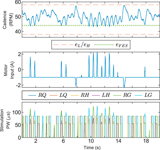
FIGURE 5. Segment of a trial using Protocol B, where alternative parameters for the barrier function controller were used. The safe set was much wider for this run, leading to less deviation of control inputs from the nominal value. Nonzero nominal inputs were used to intensify the training. The data was collected with Participant #2.
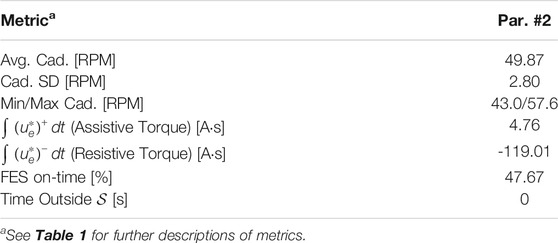
TABLE 2. Protocol B–barrier function controller: Cycling metrics during steady-state operation (140 second trial).
5.4 Discussion
The results for Protocol A demonstrate that the barrier function controller can assist a rider in tracking the cadence setpoint while constraining their cadence within a user-defined range. Figure 3 shows that the control inputs ramp up before the cadence reaches the boundaries defined by eH, eL, and eFES, yet are inactive when the cadence is near the setpoint. Such a ramp-up is demonstrative of how barrier function methods can ensure a gradual transition from a nominal controller, which should be active on the interior of the safe set, to an invariance-ensuring controller on the boundary of the safe set. For Protocol A, the width of the nominal control range was fairly small, while the width was increased for Protocol B.
In some situations, increasing the training intensity for the rider will be preferred over improved cadence tracking. The relevant statistics are the assistive and resistive torques produced by the electric motor. Higher assistive torque indicates that less power is being produced by the rider. The barrier function controller is versatile and can be tuned to provide more or less interference from the control inputs. Figure 5 shows a trial using Protocol B where power output from the rider was prioritized by allowing larger cadence errors. The system’s operator can allow larger cadence errors by selecting a wider safe range, which also facilitates the design of a wider nominal control range. The use of nominal controllers for Protocol B intensified the training by providing more FES stimulation and resistance from the motor. The control inputs were at their nominal values for a significant portion of the experiment, validating that a wider safe range leads to less modification of the nominal inputs. The nominal inputs can alternatively be designed so there is less resistance from the motor or less control input overall. The fact that the assistive torque from the barrier function controller was comparable to the 3M controller suggests that staggering FES assistance before motor assistance, as in the barrier function controller, is a viable alternative to discrete switching between FES and motor control, as in the 3M controller.
A continuous motor controller is more comfortable for the rider. Continuity is the primary difference between the barrier function and 3M controller. The 3M controller is discontinuous whenever the cadence crosses the boundary of the inactive zone, or the angular position crosses the boundary of the FES stimulation regions
There were some small deviations from the safe set because the asymptotic stability of
6 Conclusion
This paper developed new FES and motor controllers that encourage the rider of a stationary cycle to provide volitional effort while constraining their cadence within a user-defined range. Using theoretical advances for barrier functions, the controllers are minimally invasive while transitioning gradually to a safety-ensuring controller on the boundary of the safe set. The control inputs are selected from regulation maps with sufficient regularity to ensure that optimal selections are locally Lipschitz functions of the cadence error. Robust control tools were used to develop the regulation maps, which are subsets of an original, uncertain map. The uniform global asymptotic stability of the user-defined safe set was certified with a hybrid system analysis. In the future, the performance of the controller can be improved by extending the development to a more complete dynamic model which accounts for muscle activation effects such as electromechanical delay in the rider’s muscles.
Experimental results showed that the control system improved the rider’s cadence tracking and effectively constrained their cadence within the safe set. The versatility of the controller was demonstrated with trials featuring two different objectives: improved cadence tracking or more power output from the rider. A significant next step is to perform more rigorous experiments on a set of participants with neurological conditions. These riders have a reduced ability to provide volitional contributions, so the results are expected to be significantly different from those of able-bodied riders, and would be of interest in more clinically focused literature.
Data Availability Statement
The raw data supporting the conclusions of this article will be made available by the authors, without undue reservation.
Ethics Statement
The studies involving human participants were reviewed and approved by University of Florida Institutional Review Board (IRB201600881). The patients/participants provided their written informed consent to participate in this study.
Author Contributions
AI designed the controller and experiment, wrote the manuscript, and processed experimental results. BA provided multiple reviews of the manuscript and conducted the experiments. WD and RS provided technical guidance and edited the article. All authors contributed to manuscript revision, read, and approved the submitted version.
Funding
This research is supported in part by AFOSR award no. FA9550-19-1-0169, award no. FA9550-19-1-0053, and award no. FA9550-20-1-0238; by NSF award no. ECS-1710621, award no. CNS-1544396, award no. CNS-2039054, and award no. 1762829; and by the Army Research Office under Grant no. W911NF-20-1-0253. Any opinions, findings and conclusions or recommendations expressed in this material are those of the author(s) and do not necessarily reflect the views of the sponsoring agency.
Conflict of Interest
The handling Editor declared a past co-authorship with one of the authors WD.
The remaining authors declare that the research was conducted in the absence of any commercial or financial relationships that could be construed as a potential conflict of interest.
Publisher’s Note
All claims expressed in this article are solely those of the authors and do not necessarily represent those of their affiliated organizations, or those of the publisher, the editors and the reviewers. Any product that may be evaluated in this article, or claim that may be made by its manufacturer, is not guaranteed or endorsed by the publisher.
Footnotes
1For vectors
2The addition of a point
3Using the transformation in Eq. 5, we frequently use e in place of the cadence state z2.
4A set that is UGAS is also forward invariant, meaning that trajectories starting inside the set remain in the set for all of time.
5While the gain conditions in Eq. 16 will be needed to guarantee that the cadence is constrained to the set
6The positive saturation function
7While more general techniques can be developed, it is sufficient here to define
8A function
9A set
10Advanced Motion Controls supported the development of the testbed by providing discounts on their branded items.
11In the 3M controller, the user defines a region where no control is applied. An asymptotically stable region will be induced by the selection of the control gains, but it is not possible to compute this region explicitly. In the barrier function controller, the user defines the safe set boundary, while a computable region of no-control is induced by the selection of the control gains, and guaranteed to exist by Lemma 1.
12Practical improvements like muscle-dependent control gains are not included in the theoretical development for simplicity.
References
Ames, A. D., Coogan, S., Egerstedt, M., Notomista, G., Sreenath, K., and Tabuada, P. (2019). “Control Barrier Functions: Theory and Applications,” in Proc. Eur. Control Conf. (IEEE), 3420–3431. doi:10.23919/ecc.2019.8796030
Ames, A. D., Xu, X., Grizzle, J. W., and Tabuada, P. (2016). Control Barrier Function Based Quadratic Programs for Safety Critical Systems. IEEE Trans. Autom Control. 62, 3861–3876.
Asl, H. J., Yamashita, M., Narikiyo, T., and Kawanishi, M. (2020). Field-based Assist-As-Needed Control Schemes for Rehabilitation Robots. Ieee/asme Trans. Mechatron. 25, 2100–2111. doi:10.1109/tmech.2020.2992090
Bellman, M. J., Downey, R. J., Parikh, A., and Dixon, W. E. (2017). Automatic Control of Cycling Induced by Functional Electrical Stimulation with Electric Motor Assistance. IEEE Trans. Automat. Sci. Eng. 14, 1225–1234. doi:10.1109/TASE.2016.2527716
Cai, C., and Teel, A. R. (2009). Characterizations of Input-To-State Stability for Hybrid Systems. Syst. Control. Lett. 58, 47–53. doi:10.1016/j.sysconle.2008.07.009
Cousin, C. A., Duenas, V. H., Rouse, C. A., Bellman, M. J., Freeborn, P., Fox, E. J., et al. (2020). Closed-loop Cadence and Instantaneous Power Control on a Motorized Functional Electrical Stimulation Cycle. IEEE Trans. Contr. Syst. Technol. 28, 2276–2291. doi:10.1109/tcst.2019.2937725
Dao, Q.-T., and Yamamoto, S.-i. (2018). Assist-as-needed Control of a Robotic Orthosis Actuated by Pneumatic Artificial Muscle for Gait Rehabilitation. Appl. Sci. 8, 499. doi:10.3390/app8040499
Ding, B., Ai, Q., Liu, Q., and Meng, W. (2014). “Path Control of a Rehabilitation Robot Using Virtual Tunnel and Adaptive Impedance Controller,” in 2014 Seventh International Symposium on Computational Intelligence and Design (IEEE), 158–161. doi:10.1109/iscid.2014.204
Duenas, V. H., Cousin, C. A., Rouse, C., Fox, E. J., and Dixon, W. E. (2020). Distributed Repetitive Learning Control for Cooperative Cadence Tracking in Functional Electrical Stimulation Cycling. IEEE Trans. Cybern. 50, 1084–1095. doi:10.1109/tcyb.2018.2882755
Ferrante, S., Pedrocchi, A., Ferrigno, G., and Molteni, F. (2008). Cycling Induced by Functional Electrical Stimulation Improves the Muscular Strength and the Motor Control of Individuals with post-acute Stroke. Europa Medicophysica-SIMFER 2007 Award Winner. Eur. J. Phys. Rehabil. Med. 44, 159–167.
Freeman, R. A., and Kokotovic, P. V. (1996). Robust Nonlinear Control Design: State-Space and Lyapunov Techniques. Boston, MA: Birkhäuser.
Glotfelter, P., Cortés, J., and Egerstedt, M. (2017). Nonsmooth Barrier Functions with Applications to Multi-Robot Systems. IEEE Control. Syst. Lett. 1, 310–315. doi:10.1109/lcsys.2017.2710943
Goebel, R. G., Sanfelice, R., and Teel, A. R. (2012). Hybrid Dynamical Systems. Princeton University Press.
Harrington, A. T., McRae, C. G. A., and Lee, S. C. K. (2012). Evaluation of Functional Electrical Stimulation to Assist Cycling in Four Adolescents with Spastic Cerebral Palsy. Int. J. Pediatr. 2012, 1–11. doi:10.1155/2012/504387
Hooker, S. P., Figoni, S. F., Rodgers, M. M., Glaser, R. M., Mathews, T., Suryaprasad, A. G., et al. (1992). Physiologic Effects of Electrical Stimulation Leg Cycle Exercise Training in Spinal Cord Injured Persons. Arch. Phys. Med. Rehabil. 73, 470–476.
Idsø, E. S. (2002). Development of a Mathematical Model of a Rider-Tricycle System. Trondheim: Norwegian University of Science and Technology.
Isaly, A., Allen, B. C., Sanfelice, R., and Dixon, W. E. (2020). “Zeroing Control Barrier Functions for Safe Volitional Pedaling in a Motorized Cycle,” in IFAC Conf. Cyber-Phys. Hum.-Syst. (IEEE). doi:10.1016/j.ifacol.2021.04.100
Janssen, T. W., Beltman, J. M., Elich, P., Koppe, P. A., Konijnenbelt, H., de Haan, A., et al. (2008). Effects of Electric Stimulation−Assisted Cycling Training in People with Chronic Stroke. Arch. Phys. Med. Rehabil. 89, 463–469. doi:10.1016/j.apmr.2007.09.028
Johnston, T. E., Smith, B. T., Oladeji, O., Betz, R. R., and Lauer, R. T. (2008). Outcomes of a home Cycling Program Using Functional Electrical Stimulation or Passive Motion for Children with Spinal Cord Injury: a Case Series. J. Spinal Cord Med. 31, 215–221. doi:10.1080/10790268.2008.11760715
Johnston, T. E., and Wainwright, S. F. (2011). Cycling with Functional Electrical Stimulation in an Adult with Spastic Diplegic Cerebral Palsy. Phys. Ther. 91, 970–982. doi:10.2522/ptj.20100286
Kamalapurkar, R., Dixon, W. E., and Teel, A. (2020). On Reduction of Differential Inclusions and Lyapunov Stability. Esaim: Control Optim. Calc. 26, 1–16. doi:10.1051/cocv/2019074
MacKay-Lyons, M. J., and Makrides, L. (2002). Cardiovascular Stress during a Contemporary Stroke Rehabilitation Program: Is the Intensity Adequate to Induce a Training Effect? Arch. Phys. Med. Rehabil. 83, 1378–1383. doi:10.1053/apmr.2002.35089
Maghenem, M., and Sanfelice, R. G. (2021). Sufficient Conditions for Forward Invariance and Contractivity in Hybrid Inclusions Using Barrier Functions. Automatica 124, 109328. doi:10.1016/j.automatica.2020.109328
Mohr, T., Pødenphant, J., Biering–Sørensen, F., Galbo, H., Thamsborg, G., and Kjær, M. (1997). Increased Bone mineral Density after Prolonged Electrically Induced Cycle Training of Paralyzed Limbs in Spinal Cord Injured Man. Calcif. Tissue Int. 61, 22–25. doi:10.1007/s002239900286
Ouellette, M. M., LeBrasseur, N. K., Bean, J. F., Phillips, E., Stein, J., Frontera, W. R., et al. (2004). High-intensity Resistance Training Improves Muscle Strength, Self-Reported Function, and Disability in Long-Term Stroke Survivors. Stroke 35, 1404–1409. doi:10.1161/01.str.0000127785.73065.34
Pehlivan, A. U., Losey, D. P., and O’Malley, M. K. (2015). Minimal Assist-As-Needed Controller for Upper Limb Robotic Rehabilitation. IEEE Trans. Robot. 32, 113–124.
Rouse, C. A., Downey, R. J., Gregory, C. M., Cousin, C. A., Duenas, V. H., and Dixon, W. E. (2020). FES Cycling in Stroke: Novel Closed-Loop Algorithm Accommodates Differences in Functional Impairments. IEEE Trans. Biomed. Eng. 67, 738–749. doi:10.1109/tbme.2019.2920346
Rouse, C., Cousin, C. A., Allen, B. C., and Dixon, W. E. (2021). Shared Control for Switched Motorized FES-Cycling on a Split-Crank Cycle Accounting for Muscle Control Input Saturation. Automatica 123, 1–11. doi:10.1016/j.automatica.2020.109294
Sanfelice, R. G. (2013). On the Existence of Control Lyapunov Functions and State-Feedback Laws for Hybrid Systems. IEEE Trans. Automat. Contr. 58, 3242–3248. doi:10.1109/tac.2013.2264851
Trevisi, E., Gualdi, S., De Conti, C., Salghetti, A., Martinuzzi, A., Pedrocchi, A., et al. (2012). Cycling Induced by Functional Electrical Stimulation in Children Affected by Cerebral Palsy: Case Report. Eur. J. Phys. Rehabil. Med. 48, 135–145.
Keywords: functional electrical stimulation (FES, ) cycling, barrier function, safety-critical, euler-Lagrange, control design
Citation: Isaly A, Allen BC, Sanfelice RG and Dixon WE (2021) Encouraging Volitional Pedaling in Functional Electrical Stimulation-Assisted Cycling Using Barrier Functions. Front. Robot. AI 8:742986. doi: 10.3389/frobt.2021.742986
Received: 17 July 2021; Accepted: 27 September 2021;
Published: 24 November 2021.
Edited by:
Zhen Kan, University of Science and Technology of China, ChinaReviewed by:
Nitin Sharma, North Carolina State University, United StatesChaozhe He, University of Michigan, United States
Copyright © 2021 Isaly, Allen, Sanfelice and Dixon. This is an open-access article distributed under the terms of the Creative Commons Attribution License (CC BY). The use, distribution or reproduction in other forums is permitted, provided the original author(s) and the copyright owner(s) are credited and that the original publication in this journal is cited, in accordance with accepted academic practice. No use, distribution or reproduction is permitted which does not comply with these terms.
*Correspondence: Axton Isaly, axtonisaly1013@ufl.edu