Anti-Disturbance Sliding Mode Control of a Novel Variable Stiffness Actuator for the Rehabilitation of Neurologically Disabled Patients
 Lufan Mo
 Pengbo Feng2
 - 1School of Mechanical Engineering and Automation, Beihang University, Beijing, China
- 2Beihang Goer (WeiFang) Intelligent Robot Co., Ltd, Weifang, China
- 3Beijing Advanced Innovation Centre for Biomedical Engineering, Beihang University, Beijing, China
Lower limb exoskeletons are widely used for rehabilitation training of patients suffering from neurological disorders. To improve the human–robot interaction performance, series elastic actuators (SEAs) with low output impedance have been developed. However, the adaptability and control performance are limited by the constant spring stiffness used in current SEAs. In this study, a novel load-adaptive variable stiffness actuator (LaVSA) is used to design an ankle exoskeleton. To overcome the problems of the LaVSA with a larger mechanical gap and more complex dynamic model, a sliding mode controller based on a disturbance observer is proposed. During the interaction process, due to the passive joints at the load side of the ankle exoskeleton, the dynamic parameters on the load side of the ankle exoskeleton will change continuously. To avoid this problem, the designed controller treats it and the model error as a disturbance and observes it with the disturbance observer (DOB) in real time. The first-order derivative of the disturbance set is treated as a bounded value. Subsequently, the parameter adaptive law is used to find the upper bound of the observation error and make corresponding compensation in the control law. On these bases, a sliding mode controller based on a disturbance observer is designed, and Lyapunov stability analysis is given. Finally, simulation and experimental verification are performed. The wearing experiment shows that the resistance torque suffered by humans under human–robot interaction is lower than 120 Nmm, which confirms that the controller can realize zero-impedance control of the designed ankle exoskeleton.
Introduction
Neurological disorders, such as stroke, Perkins syndrome, and cerebral apoplexy, can lead to long-term loss of motor function or even paralysis (WHO, 2006), which is undoubtedly a type of torture for patients. In response to this problem, research on rehabilitation of lower limb exoskeleton robots, such as BLEEX (Kazerooni et al., 2006), ALEX (Banala et al., 2010), Rewalk (Zeilig et al., 2012), Ekso (Pransky, 2014), and HEXAR (Kim et al., 2014), has gradually become a hot topic. Safe physical human–robot interaction (pHRI) is an essential characteristic of exoskeleton robots (De Santis et al., 2008; Falzarano et al., 2019; Shi et al., 2019). Thus, serial elastic actuators (SEAs) with compliance were introduced (Pratt and Williamson, 1995). However, a significant disadvantage of SEAs is that the stiffness is constant, which limits the energy storage capacity and bandwidth of the actuator (Kim et al., 2014). Therefore, a variable stiffness actuator (VSA) was designed as an improvement of the SEAs. Generally, VSA adopts two motors, one for controlling the stiffness and another for controlling the motion of the load side (Jafari et al., 2011; Wolf et al., 2011; Shao et al., 2021a). This makes the stiffness adjustment more flexible. For example, in the work of Shao et al. (2021a), it was proposed that the effective length of the force arm can be adjusted by the stiffness motor adjusting the contact point of the fulcrum on the lever to obtain variable stiffness. The stiffness motor is not affected by the load, which can greatly save energy compared to the VSA using the antagonistic principle (Popov et al., 2014). However, to achieve the lightweight and compact exoskeleton robot, the use of two motors is not a good choice. As an alternative, some scholars have studied non-linear variable stiffness actuators, which use only one motor (Thorson and Caldwell, 2011; Yu et al., 2013; Schepelmann et al., 2014; Shao et al., 2019; Hu et al., 2020; Shao et al., 2021b). Usually, human-like characteristics (small torque and low stiffness and large torque and large stiffness) are considered in non-linear VSA (Zhu et al., 2021). In the work of Thorson and Caldwell (2011), planetary gear mechanisms were introduced to obtain non-linear characteristics. In the work of Hu et al. (2020), multiple symmetric cams were introduced to bidirectional non-linear characteristics. Both methods increase the size of the actuator. In the work of Shao et al. (2021b), a compact load-adaptive variable stiffness actuator (LaVSA) was designed, which was inspired by the structure of the human ankle joint. LaVSA can customize the cam profile to alter the stiffness curve and be more energy efficient, lighter, and more compact than SEAs. However, as discussed in Preliminary, these advantages of LaVSA also bring complexity at the mechanical level and larger mechanical clearance and friction, which make the controller more robust.
Due to the introduction of variable stiffness, there is usually a larger gap in the VSA system. The machining accuracy makes it difficult to ensure that the stiffness curve achieves the expected effect. In addition, variable stiffness will result in non-linear problems such as backlash, hysteresis, and dead zones (Zhao et al., 2019). These will greatly increase the inaccuracy and chattering of the control. To overcome these problems, various control methods have been proposed in recent years. They are mainly divided into three categories: position control, force control, and force position hybrid control (Meng et al., 2015). Position-based tracking control is significant in the early rehabilitation phase when the impaired limb is unable to move. In the work of Sardellitti et al. (2012), a gain scheduling method based on a linear quadratic regulator (LQR) was proposed to obtain high-precision position control. This method can continuously adjust the control parameters according to the current stiffness of the flexible transmission. Then, in the work of Sardellitti et al. (2013), an improved controller based on LQR was proposed, and a more complete formula, experiment, and stability analysis were provided. In the work of Zhakatayev et al. (2015), a non-linear model predictive control (NMPC) algorithm was proposed to complete the hybrid control of position and speed on the load side. However, the controller requires high sensor performance and is sensitive to disturbances. Clearly, it is not suitable for ankle exoskeleton environments that are disturbed by human-robot interaction. In the work of Zhang et al. (2017), an adaptive neural network controller (NNC) based on DOB was proposed to control the joint angle of non-linear VSA. The controller shows strong robustness to disturbances, such as gap, hysteresis, and non-linearity, which are the difficulties faced in non-linear VSA control. When rehabilitation training is performed to a certain extent or the person has certain exercise ability, it should be considered that the person will take the initiative to exercise. Both force control and force position hybrid control take into account that problem. In the work of Simon et al. (2007), a hybrid position and force controller was designed to provide the target resistance force to the impaired limb to improve force symmetry in the limbs during lower limb extensions. In the work of Wang et al. (2016), a sliding mode control (SMC) strategy based on DOB was proposed. The input torque at the load side is controlled by controlling the deformation of the elastic element. To suppress the chatter problem of SMC Huang et al. (2008) introduced the saturation function instead of the symbolic function. To allow for natural variations in the patient, the robot’s position and contact force need to be adjusted in real time. The impedance control strategy is one of the most suitable force control methods. Liu et al. (2018) performed much work in this regard. A gain-scheduled torque controller that applies the Linear Quadratic Gaussian (LQG) technique to deal with the multiloop feedback in the VSA plant was proposed. An impedance control based on cascaded position-torque control loops (Liu et al., 2019) was proposed. The LQG approach is also employed here, but with additional discussion on the observer designed to serve the proposed cooperative control approach. On these bases, it is further proposed to use human joint torque as feedback and use the Lyapunov function to obtain the range of stiffness operation (Liu et al., 2021).
The compact, lightweight, and energy-efficient characteristics of LaVSA make it suitable for exoskeleton joints (Huo et al., 2014; Chen et al., 2021), especially ankle joint exoskeletons. As mentioned in Preliminary, LaVSA exhibits greater mechanical clearance and friction loss. Therefore, in this study, we designed a robust SMC based on DOB. Aiming at the irregular change of dynamic parameters at the load side of the ankle exoskeleton, the load-side dynamics and model errors are unified as disturbance, which is observed by DOB. The controller realistically treats the first-order derivative of the disturbance as a bounded value, compared to the work of Yu et al. (2015), which treats disturbance as constant. A saturation function is introduced instead of a sign function to suppress chattering. Taking into full account the initiative of people in rehabilitation training, as mentioned above, impedance control is a more commonly used method in rehabilitation exoskeletons. Then, we use DOB-based SMC for zero-impedance control of the ankle exoskeleton so that the robot can follow the movement of the patient, and the patient can move freely without much effort.
The remainder of this article is organized as follows. Preliminary presents a previously designed LaVSA prototype, focusing on the dynamic analysis and important improvements of the mechanical structure. Controller Design presents the design process of the anti-disturbance sliding mode controller for LaVSA. Simulation and Experiment presents the simulations and experiments, focusing on zero-impedance control. Finally, Conclusion presents the main conclusions.
Preliminary
System Setup
The schematic diagram of the testing platform, shown in Figure 1A, displays the main system elements. The middle of the picture shows the stable and reliable Beckhoff controller (CX2300, sampling time of 1 ms), which uses the Enthercat protocol to communicate with the ControlDesk and Elmo Drivers. Through the TwinCat3 software installed in the ControlDesk, the real-time control and feedback signal of the ankle exoskeleton system are received. The right of the picture shows the test bench equipped with the ankle exoskeleton. For safety, the emergency stop switch is connected to the circuit. Details of the LaVSA mounted on the ankle exoskeleton are shown in Figure 2A. The actuator is equipped with a Maxon EC-4pole 120 W DC servo motor, a Maxon ENX16 EASY incremental encoder, and a non-linear stiffness mechanism/elastic element, as well as an RLS RM08 12-bit absolute used to measure the joint angle. The relative displacement relative to the screw between the leaf spring and cam, which is treated as a deflection in this paper, is measured by a Miran KSF-35 linear potentiometer. The human–robot interaction scene of the ankle exoskeleton is shown in Figure 1B. The ankle joint of the human body and the ankle exoskeleton are approximately on the same axis to control the person’s plantar/dorsal flexion; ever/inversion and ex/internal rotation movements of the ankle exoskeleton are passive. Under the action of the bandage and footplate, the robot leg and the human leg are relatively stationary.
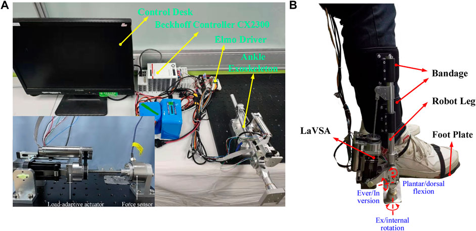
FIGURE 1. Schematic diagram of the experimental setup. (A) Testing platform. (B) Human–robot interaction scene.
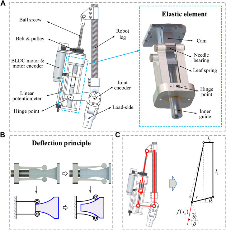
FIGURE 2. Load-adaptive variable stiffness actuator. (A) Components of the LaVSA model. (B) Leaf spring deflection principle. (C) Mechanism diagram of LaVSA.
LaVSA works as follows. The torque generated by a servo motor drives a small pulley to rotate, and the small pulley drives the large pulley to rotate so that the actuator moves on the lead screw, which in turn drives the leaf spring to move. The leaf spring and the load are hinged. When the load increases, the relative displacement between the leaf spring and the cam increases, the deformation of the leaf spring increases (the deformation principle of leaf spring is shown in Figure 2B), and the elastic force generated by the leaf spring increases. Furthermore, the driving force received by the load increases. Consequently, the motion transition of the actuator can be divided into three parts. The first part is the rotary motion of the servo motor, the small pulley, and the large pulley. The second part is the translation of the actuator on the screw. The third part is the rotational movement of the load side. In contrast to most current VSAs, such as in Wang et al. (2015) and (Hu et al. (2020), the motion transfer is only rotation-to-rotation (rotation of motor side to rotation of load side). Such more complex motion transfer will inevitably result in greater mechanical clearance and friction loss, especially at the ball screw. Different stiffness curves can be obtained by designing different cam profiles. The cam profile we use in this article will allow the actuator to achieve low-load, low-stiffness, high-load, and high-stiffness characteristics that match the motion mechanism of the human body.
Control Model
The actuator dynamic model can be divided into three parts. The first part is the rotary motion of the motor-side. The second part is the translation of the actuator. The third part is the rotary motion of the load-side. The dynamic models of these three parts are given as follows:
The motor-side model is expressed using Eq. 1, where
where
The mechanism diagram of LaVSA is shown in Figure 2C. For the convenience of calculation, the position of the joint connecting rod perpendicular to the robot leg is regarded as the initial position, and the following relationship can be obtained:
where
In the process of human-robot interaction, due to the presence of passive joints on the load side of the ankle exoskeleton, the load parameters
Combining Equations 1–7,
where
where
Force-Deflection Curve Calibration
To obtain the large force range and stiffness characteristics, we re-optimized the cam curve to make the non-linearity of force-deflection more obvious. Additionally, it should be noted that the force of the elastic body cannot exceed the service limit. This is different from the work done in a previous study (Shao et al., 2021b).
Remark 2.1. The range of the elastic element force–deformation curve is selected as follows: force is 200–200 N, deformation is 7.5–7.5 mm; the peak torque that the elastic element can withstand is
When
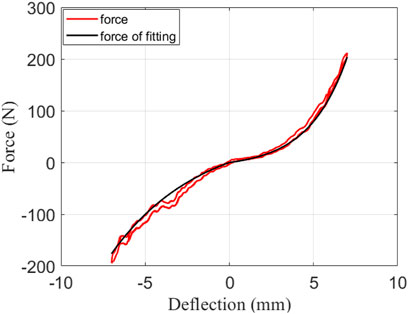
FIGURE 3. Force-deflection curve fitting diagram.

TABLE 1. Fitted parameters.
Controller Design
Control Model
A closed-loop controller based on sliding mode control, which is aimed to improve the accuracy and robustness, was designed. The following specifications were considered to establish the impedance control model for the VSA system described in Eqs 1–3.
1) Fixed-output case: Fixing the output of the VSA is a suitable test case for the controller performance. In this case, the absence of the load side model of Eq. 3 leads to elastic deflection only with respect to the position of the motor, which means that there is no need to introduce an additional sensor to measure
2) Zero-impedance control: To realize the active control of patients without much effort that can be regarded as zero-impedance control, the controller must perform torque control when the load side is not fixed. When the main driving force provided by humans drives the load to move, Eq. 3 can be expressed as
where
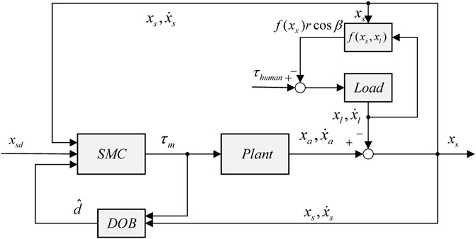
FIGURE 4. Zero-impedance control block diagram.
Torque Controller Design
In Control Model, the variation in load parameters, model error, and friction are regarded as a disturbance set. The handling of the disturbance set is an important part of the controller design. To reduce the sensitivity of the control performance to disturbance, DOB are designed to predict disturbance sets and are given as
where
By integrating both sides of the abovementioned equation, we obtain
For the sake of simplicity, some observers are usually designed based on the assumption that
It is observed that the error of the observer is affected by
where
Finally, the sliding mode control law based on the disturbance observer is derived as follows:
where
Stability Analysis
To ensure the correctness of the controller design, the following Lyapunov function is considered:
Differentiating Eq. 18 and substituting Eqs 14–17 into it yields
Integrating Eq. 19 yields
Therefore, it can be obtained that
Because
Simulation and Experiment
In this section, the results of the simulation, experimental platform test, and wearable test are presented to verify the effectiveness of the controller. The corresponding parameters are shown in Table 2. Of note, to suppress the chatter of SMC, most scholars use the saturation function instead of the sign function. This study also applies a similar approach in simulations and experiments. Its essence is that outside the boundary layer, switching control is used to rapidly make the system state in a sliding mode. In the boundary layer, feedback control is used to reduce the chattering during fast switching of sliding modes. The saturation function is as follows:

TABLE 2. System parameter and mechanism size.
Remark 4.1. The choices of dimension parameters of the mechanism (such as
Remark 4.2. In this study, the controller is designed by putting the dynamics of the load side into the disturbance set. Therefore, the dynamic parameters of the load side are not necessary.
Simulation
For the two torque control modes mentioned in Control Model, two modes were simulated to verify the correctness of the theoretical analysis and provide a basis for parameter adjustment.
1) Simulation 1: fixed output: in this group, the main purpose is to verify the stability of the controller. To simulate the irregularity of the actual disturbance set as much as possible to verify the anti-disturbance capability of the controller, the disturbance is defined as
2) Simulation 2: zero-impedance control: in this group, the main purpose is to verify the correctness of zero-impedance control. Herein, the load side moment of inertia is selected as
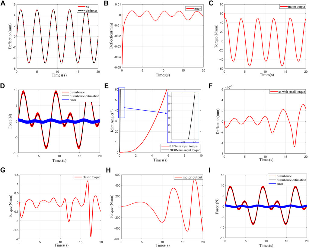
FIGURE 5. Simulation results. (A) Trajectory tracking of deflection at fixed output. (B) Error of deflection trajectory tracking at fixed output. (C) Motor output/control law at fixed output. (D) Trajectory of disturbance observation at fixed output. (E) Corresponding joint angles in zero-impedance control under different human–robot interaction torques. (F) Deflection trajectory tracking at 0.8 Nmm human–robot interaction torque under zero-impedance control. (G) Elastic torque
Experiment
After numerical simulation, we utilize the testing platform mentioned above to further verify the effectiveness of the established controller. The two different control model tests are implemented on the test platform. Subsequently, wearable zero-impedance control of the ankle exoskeleton was performed.
1) Experiment 1: fixed output: in this group, the load side is fixed. The desired trajectory is selected as
2) Experiment 2: zero-impedance control on the bench: the experimental scene is shown in Figure 1A. The external force moment is applied by hand to make the load side move according to the sinusoidal track as much as possible. The control target is
3) Experiment 3: wearing experiment of zero-impedance control: on the basis of Experiments 1 and 2, we control the ankle exoskeleton after wearing it to fundamentally verify the practicability of the controller. The experimental results are shown in Figure 7. Compared with Experiment 2, the tracking error is approximately the same, but the deflection and motor output chatter are further increased. Compared to Experiment 2, the tracking error values are approximately the same, but the deflection and the chattering of the motor output are further increased. This is mainly caused by the unstable binding between the human and the ankle exoskeleton, which makes the interaction force unstable. However, (B) shows that the resistance torque is still less than 100 Nmm, and the joint trajectory is also smooth, which indicates that the control is successful. The problems of large friction and gaps caused by this complex structure of LaVSA are solved. The proposed controller combined with LaVSA can be well applied to the ankle exoskeleton robot and can effectively solve the control problem during the active training of the patient during the rehabilitation process.
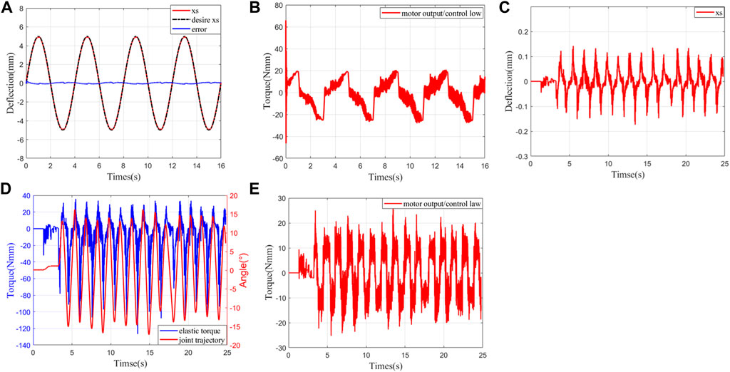
FIGURE 6. Experimental results. (A) Deflection trajectory tracking with fixed output. (B) Motor output with fixed output. (C) Deflection trajectory tracking under zero-impedance control. (D) Elastic torque and joint trajectory under zero-impedance control. (E) Motor output/control law under zero-impedance control.
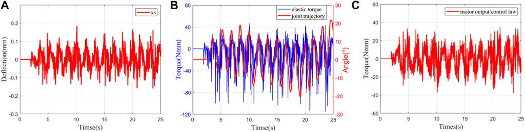
FIGURE 7. Wearing experiment results. (A) Deflection trajectory tracking. (B) Elastic torque and joint trajectory. (C) Motor output/control law.
Conclusion
In this study, we performed research on rehabilitation ankle exoskeleton robots combined with LaVSA for patients with neurological disorders, aiming at realizing the ‘patient-in-charge’ control method (Veneman et al., 2007). LaVSA has many advantages that make it very suitable as an ankle exoskeleton. However, these advantages of LaVSA also bring complexity at the mechanical level, larger mechanical gaps and more friction. Here, the model error caused by the gap and friction and the dynamic model of the load-side are regarded as the disturbance set. Its value is observed in real time with the disturbance observer. Most disturbance observers ideally regard the disturbance as a slow disturbance, which makes the first-order derivative of the disturbance equal to zero. However, in practice, the first-order derivative of disturbance is usually a bounded value. This usually leads to the failure of observation error convergence. Therefore, the parameter adaptation law is used to find an upper bound on the observation error. Then, corresponding compensation is made in the control law. Then, a disturbance observer-based sliding mode controller is designed. In addition, this study uses the deformation of the elastic body as an index to evaluate the low impedance property of the system. Finally, the simulation and experimental results confirm that the controller allows the patient to move freely without effort. However, because the sensor is not sufficiently good, the second-order derivative of the acquired signal is too large, which makes the control law too large. This is also a cause of chatter. Subsequent work may need to be optimized.
Data Availability Statement
The original contributions presented in the study are included in the article/Supplementary Material, further inquiries can be directed to the corresponding author.
Author Contributions
All authors contributed to the theory, implementation, and numerical/experimental validation of this study. More specifically, LM developed the theory, designed the control algorithm, and conducted the simulations and real hardware experiments in this paper. PF provided guidance for the article and provided corresponding financial support for the experiments. YS contributed to the design of LaVSA. DS and LJ provided suggestions for the paper. WZ and XD supervised this research and revised the submitted manuscript.
Funding
This work was supported by the National Natural Science Foundation of China (NSFC) under grant No. 91848104.
Conflict of Interest
The author PF was employed by Beihang Goer (WeiFang) Intelligent Robot Co., Ltd.
The remaining authors declare that the research was conducted in the absence of any commercial or financial relationships that could be construed as a potential conflict of interest.
Publisher’s Note
All claims expressed in this article are solely those of the authors and do not necessarily represent those of their affiliated organizations, or those of the publisher, the editors, and the reviewers. Any product that may be evaluated in this article, or claim that may be made by its manufacturer, is not guaranteed or endorsed by the publisher.
References
Banala, S. K., Agrawal, S. K., Seok Hun Kim, S. H., and Scholz, J. P. (2010). Novel Gait Adaptation and Neuromotor Training Results Using an Active Leg Exoskeleton. Ieee/asme Trans. Mechatron. 15 (2), 216–225. doi:10.1109/tmech.2010.2041245
Chen, L., Chen, C., Wang, Z., Ye, X., Liu, Y., and Wu, X. (2021). A Novel Lightweight Wearable Soft Exosuit for Reducing the Metabolic Rate and Muscle Fatigue. Biosensors 11 (7), 215. doi:10.3390/bios11070215
De Santis, A., Siciliano, B., De Luca, A., and Bicchi, A. (2008). An Atlas of Physical Human-Robot Interaction. Mechanism Machine Theor. 43 (3), 253–270. doi:10.1016/j.mechmachtheory.2007.03.003
Falzarano, V., Marini, F., Morasso, P., and Zenzeri, J. (2019). Devices and Protocols for Upper Limb Robot-Assisted Rehabilitation of Children with Neuromotor Disorders. Appl. Sci. 9 (13), 2689. doi:10.3390/app9132689
Hu, X., Song, Z., and Ma, T. (2020). Novel Design Method for Nonlinear Stiffness Actuator with User-Defined Deflection-Torque Profiles. Mechanism Machine Theor. 146, 103712. doi:10.1016/j.mechmachtheory.2019.103712
Huang, Y.-J., Kuo, T.-C., and Chang, S.-H. (2008). Adaptive Sliding-Mode Control for Nonlinearsystems with Uncertain Parameters. IEEE Trans. Syst. Man. Cybern. B 38 (2), 534–539. doi:10.1109/tsmcb.2007.910740
Huo, W., Mohammed, S., Moreno, J. C., and Amirat, Y. (2014). Lower Limb Wearable Robots for Assistance and Rehabilitation: A State of the Art. IEEE Syst. J. 10 (3), 1068–1081. doi:10.1109/JSYST.2014.2351491
Jafari, A., Tsagarakis, N. G., and Caldwell, D. G. (2011). A Novel Intrinsically Energy Efficient Actuator with Adjustable Stiffness (AwAS). IEEE/ASME Trans. mechatronics 18 (1), 355–365. doi:10.1109/TMECH.2011.2177098
Kazerooni, H., Steger, R., and Huang, L. (2006). Hybrid Control of the Berkeley Lower Extremity Exoskeleton (BLEEX). Int. J. Robotics Res. 25 (5-6), 561–573. doi:10.1177/0278364906065505
Kim, W., Lee, H., Kim, D., Han, J., and Han, C. (2014). “Mechanical Design of the Hanyang Exoskeleton Assistive Robot (HEXAR),” in 2014 14th international conference on control, automation and systems (ICCAS 2014), Gyeonggi-do, Korea (South), October 22–25, 2014 (IEEE), 479–484. doi:10.1109/iccas.2014.6988049
Liu, L., Leonhardt, S., and Misgeld, B. J. E. (2018). Experimental Validation of a Torque-Controlled Variable Stiffness Actuator Tuned by Gain Scheduling. Ieee/asme Trans. Mechatron. 23, 2109–2120. doi:10.1109/tmech.2018.2854416
Liu, L., Leonhardt, S., Ngo, C., and Misgeld, B. J. E. (2020). Impedance-Controlled Variable Stiffness Actuator for Lower Limb Robot Applications. IEEE Trans. Automat. Sci. Eng. 17, 991–1004. doi:10.1109/tase.2019.2954769
Liu, L., Misgeld, B. J. E., Pomprapa, A., and Leonhardt, S. (2021). A Testable Robust Stability Framework for the Variable Impedance Control of 1-DOF Exoskeleton with Variable Stiffness Actuator. IEEE Trans. Contr. Syst. Technol. 29, 2728–2737. doi:10.1109/tcst.2021.3051716
Meng, W., Liu, Q., Zhou, Z., Ai, Q., Sheng, B., and Xie, S. (2015). Recent Development of Mechanisms and Control Strategies for Robot-Assisted Lower Limb Rehabilitation. Mechatronics 31, 132–145. doi:10.1016/j.mechatronics.2015.04.005
Popov, D., Gaponov, I., and Ryu, J.-H. (2014). “Towards Variable Stiffness Control of Antagonistic Twisted String Actuators,” in 2014 IEEE/RSJ International Conference on Intelligent Robots and Systems (IEEE), 2789–2794. doi:10.1109/IROS.2014.6942944
Pransky, J. (2014). The Pransky Interview: Russ Angold, Co-founder and President of Ekso™ Labs. Ind. Robot: Int. J. 41 (4), 329–334. doi:10.1108/IR-05-2014-0334
Pratt, G. A., and Williamson, M. M. (1995). “Series Elastic Actuators,” in Proceedings 1995 IEEE/RSJ International Conference on Intelligent Robots and Systems. Human Robot Interaction and Cooperative Robots, Pittsburgh, PA, August 5–9, 1995 (IEEE), 399–406. doi:10.1109/IROS.1995.525827
Sardellitti, I., Medrano-Cerda, G. A., Tsagarakis, N., Jafari, A., and Caldwell, D. G. (2013). Gain Scheduling Control for a Class of Variable Stiffness Actuators Based on Lever Mechanisms. IEEE Trans. Robot. 29 (3), 791–798. doi:10.1109/tro.2013.2244787
Sardellitti, I., Medrano-Cerda, G., Tsagarakis, N. G., Jafari, A., and Caldwell, D. G. (2012). “A Position and Stiffness Control Strategy for Variable Stiffness Actuators,” in 2012 IEEE International Conference on Robotics and Automation, Saint Paul, MN, May 14–18, 2012. doi:10.1109/ICRA.2012.6224672
Schepelmann, A., Geberth, K. A., and Geyer, H. (2014). “Compact Nonlinear Springs with User Defined Torque-Deflection Profiles for Series Elastic Actuators,” in : 2014 ieee international conference on robotics and automation (icra), Hong Kong, China, May 31–June 7, 2014 (IEEE), 3411–3416. doi:10.1109/icra.2014.6907350
Shao, Y., Zhang, W., and Ding, X. (2021a). Configuration Synthesis of Variable Stiffness Mechanisms Based on Guide-Bar Mechanisms with Length-Adjustable Links. Mechanism Machine Theor. 156, 104153. doi:10.1016/j.mechmachtheory.2020.104153
Shao, Y., Zhang, W., Su, Y., and Ding, X. (2021b). Design and Optimisation of Load-Adaptive Actuator with Variable Stiffness for Compact Ankle Exoskeleton. Mechanism Machine Theor. 161, 104323. doi:10.1016/j.mechmachtheory.2021.104323
Shao, Y., Zhang, W., Xu, K., and Ding, X. (2019). “Design of a Novel Compact Adaptive Ankle Exoskeleton for Walking Assistance,” in IFToMM World Congress on Mechanism and Machine Science, Krakow, Poland, July 15–18, 2019 (Springer), 2159–2168. doi:10.1007/978-3-030-20131-9_214
Shi, D., Zhang, W., Zhang, W., and Ding, X. (2019). A Review on Lower Limb Rehabilitation Exoskeleton Robots. Chin. J. Mech. Eng. 32 (1), 1–11. doi:10.1186/s10033-019-0389-8
Simon, A. M., Brent Gillespie, R., and Ferris, D. P. (2007). Symmetry-based Resistance as a Novel Means of Lower Limb Rehabilitation. J. Biomech. 40 (6), 1286–1292. doi:10.1016/j.jbiomech.2006.05.021
Thorson, I., and Caldwell, D. (2011) “A Nonlinear Series Elastic Actuator for Highly Dynamic Motions,” in 2011 IEEE/RSJ International Conference on Intelligent Robots and Systems, San Francisco, CA, September 25–30, 2011 (IEEE), 390–394. doi:10.1109/IROS.2011.6048581
Veneman, J. F., Kruidhof, R., Hekman, E. E. G., Ekkelenkamp, R., Van Asseldonk, E. H. F., and Van Der Kooij, H. (2007). Design and Evaluation of the LOPES Exoskeleton Robot for Interactive Gait Rehabilitation. IEEE Trans. Neural Syst. Rehabil. Eng. 15 (3), 379–386. doi:10.1109/tnsre.2007.903919
Wang, M., Sun, L., Yin, W., Dong, S., and Liu, J. (2016). “Nonlinear Disturbance Observer Based Torque Control for Series Elastic Actuator,” in 2016 IEEE/RSJ International Conference on Intelligent Robots and Systems (IROS), Daejeon, Korea (South), October 9–14, 2016 (IEEE), 286–291. doi:10.1109/iros.2016.7759068
Wang, Z., Yip, H. M., Navarro-Alarcon, D., Li, P., Liu, Y.-h., Sun, D., et al. (2015). Design of a Novel Compliant Safe Robot Joint with Multiple Working States. IEEE/ASME Trans. Mechatronics 21 (2), 1193–1198. doi:10.1109/TMECH.2015.2500602
Witte, K. A., Fiers, P., Sheets-Singer, A. L., and Collins, S. H. (2020). Improving the Energy Economy of Human Running with Powered and Unpowered Ankle Exoskeleton Assistance. Sci. Robot 5 (40), eaay9108. doi:10.1126/scirobotics.aay9108
Wolf, S., Eiberger, O., and Hirzinger, G. (2011). “The DLR FSJ: Energy Based Design of a Variable Stiffness Joint,” in : 2011 IEEE International Conference on Robotics and Automation (IEEE), 5082–5089. doi:10.1109/ICRA.2011.5980303
Yu, H., Huang, S., Chen, G., Pan, Y., and Guo, Z. (2015). Human-Robot Interaction Control of Rehabilitation Robots with Series Elastic Actuators. IEEE Trans. Robot. 31 (5), 1089–1100. doi:10.1109/tro.2015.2457314
Yu, H., Huang, S., Chen, G., and Thakor, N. (2013). Control Design of a Novel Compliant Actuator for Rehabilitation Robots. Mechatronics 23 (8), 1072–1083. doi:10.1016/j.mechatronics.2013.08.004
Zeilig, G., Weingarden, H., Zwecker, M., Dudkiewicz, I., Bloch, A., and Esquenazi, A. (2012). Safety and Tolerance of the ReWalkexoskeleton Suit for Ambulation by People with Complete Spinal Cord Injury: A Pilot Study. J. spinal cord Med. 35 (2), 96–101. doi:10.1179/2045772312y.0000000003
Zhakatayev, A., Rubagotti, M., and Varol, H. A. (2015). Closed-loop Control of Variable Stiffness Actuated Robots via Nonlinear Model Predictive Control. IEEE Access 3, 235–248. doi:10.1109/access.2015.2418157
Zhang, L., Li, Z., and Yang, C. (2017). Adaptive Neural Network Based Variable Stiffness Control of Uncertain Robotic Systems Using Disturbance Observer. IEEE Trans. Ind. Electron. 64 (3), 2236–2245. doi:10.1109/tie.2016.2624260
Zhao, Y., Song, Z., Ma, T., and Dai, J. S. (2019). A Stiffness-Adaptive Control System for Nonlinear Stiffness Actuators. Sci. China Inf. Sci. 62 (5), 1–3. doi:10.1007/s11432-018-9666-y
Keywords: neurological disorders, rehabilitation exoskeleton robot, variable stiffness actuator, sliding mode control, impedance control
Citation: Mo L, Feng P, Shao Y, Shi D, Ju L, Zhang W and Ding X (2022) Anti-Disturbance Sliding Mode Control of a Novel Variable Stiffness Actuator for the Rehabilitation of Neurologically Disabled Patients. Front. Robot. AI 9:864684. doi: 10.3389/frobt.2022.864684
Received: 28 January 2022; Accepted: 18 March 2022;
Published: 02 May 2022.
Edited by:
Rogério Gonçalves, Federal University of Uberlandia, BrazilReviewed by:
Adriano A. Gonçalves Siqueira, University of São Paulo, BrazilTanvir Ahmed, University of Wisconsin–Milwaukee, United States
Copyright © 2022 Mo, Feng, Shao, Shi, Ju, Zhang and Ding. This is an open-access article distributed under the terms of the Creative Commons Attribution License (CC BY). The use, distribution or reproduction in other forums is permitted, provided the original author(s) and the copyright owner(s) are credited and that the original publication in this journal is cited, in accordance with accepted academic practice. No use, distribution or reproduction is permitted which does not comply with these terms.
*Correspondence: Di Shi, shidi@buaa.edu.cn