Using Deep Neural Networks to Improve Contact Wrench Estimation of Serial Robotic Manipulators in Static Tasks
 Jonas Osburg
 Ivo Kuhlemann1†‡
  Jannis Hagenah
 Floris Ernst
- 1Institute for Robotics and Cognitive Systems, University of Lübeck, Lübeck, Germany
- 2Department of Engineering Science, University of Oxford, Oxford, United Kingdom
Reliable force-driven robot-interaction requires precise contact wrench measurements. In most robot systems these measurements are severely incorrect and in most manipulation tasks expensive additional force sensors are installed. We follow a learning approach to train the dependencies between joint torques and end-effector contact wrenches. We used a redundant serial light-weight manipulator (KUKA iiwa 7 R800) with integrated force estimation based on the joint torques measured in each of the robot’s seven axes. Firstly, a simulated dataset is created to let a feed-forward net learn the relationship between end-effector contact wrenches and joint torques for a static case. Secondly, an extensive real training dataset was acquired with 330,000 randomized robot positions and end-effector contact wrenches and used for retraining the simulated trained feed-forward net. We can show that the wrench prediction error could be reduced by around 57% for the forces compared to the manufacturer’s proprietary force estimation model. In addition, we show that the number of high outliers can be reduced substantially. Furthermore we prove that the approach could be also transferred to another robot (KUKA iiwa 14 R820) with reasonable prediction accuracy and without the need of acquiring new robot specific data.
1 Introduction
1.1 Motivation
Compliant robotic arms have increasingly gained importance during the last years, where anthropomorphic kinematically redundant serial manipulators with seven degrees of freedom (DoF) are frequently used for various new applications. Integrated joint torque sensors provide crucial functionalities for safe human-robot-interactions. Based on the joint torques τ, measured in each of the robot’s axes, the corresponding contact forces f applied to the robot’s end-effector can be calculated. Obviously, a higher accuracy of the determined forces leads to enhanced overall sensitivity of the robot, and therefore allows for more complex applications. On the other hand, errors in the computational model can lead to dangerous and harmful situations during force driven operations. For industrial manipulators, no individual but rather general mechanical models are used for the control algorithms. Manufacturing inaccuracies and individual characteristics of bearings, sensors and actuators are often neglected. As a result, this leads to further sources of error in contact force determination and can have a strong influence on the resulting accuracy. In a dynamic scenario with high accelerations and velocities, mass induced inertial, centrifugal and Coriolis forces at the manipulator must be considered in the control algorithms Khatib (1987). For a static scenario the determination of end-effector contact forces is greatly simplified. Finally, only the inverted geometric Jacobian Matrix is required to express the relationship between forces and joint torques Schweikard and Ernst (2015). Whenever computational models use the Jacobian Matrix for motion and force control, the matrix loses full-rank at singularities, causing the computation of contact forces to fail Maciejewski (1991).
Furthermore, robots are usually not used in their full performance range, but operate in a very small range of forces due to the rather restricted type of specialized applications. Therefore, an optimized calibration within this specific range of forces could lead to very precise results, minimized errors and drastically increased overall system accuracy.
One approach to increase the accuracy of the contact force calculation is machine learning. Artificial neural networks show impressive capabilities in solving direct Sadjadian et al. (2005) and inverse kinematics Raj et al. (2015) as well as in dynamic control of redundant manipulators Kumar et al. (2011a), Lian (2014), Li et al. (2017). Earlier research addressed the calibration of force/torque sensors for serial robotic manipulators, mostly focusing on optimizing linear relations between joint torques and dynamic parameters known as the Inverse Dynamic Identification Model (IDIM) Khosla and Kanade (1985), Hollerbach et al. (2008), Gautier and Jubien (2014). Learning approaches to optimize the IDIM were presented in Kumar et al. (2011b), Pei et al. (1992), Jung et al. (2001). In Lu et al. (1997), neural networks are used to map measured signals and resulting forces, to calibrate an external force/torque sensor mounted to an end-effector. Although the authors show accurate results and provide time-saving routines, unfortunately, instabilities near singularities still exist or additional external sensors are required. Smith et al. showed interesting results by using a neural-network-based approach to determine contact forces for haptic devices Smith et al. (2006). Unfortunately, the authors have to use biased ground truth data and, therefore, it remains unclear how this affects the calibration accuracy.
An approach using deep learning for reducing errors in identification of dynamic parameters of a 6-DoF robot is presented in Wang et al. (2020). Moreover Lutter et al. (2019) include physical laws of the system (in form of the Euler-Lagrange equation) into deep neural network architectures. Thus more accurate models can be obtained whilst ensuring physical plausibility. However the papers do not relate to force estimation at the end-effector. This is done in Kružić et al. (2021), where deep learning is used to estimate end-effector forces and joint torques of a 7-DoF robotic manipulator. Even though promising results are shown, a validation of the estimation end-effector forces and moments on a real robot is missing.
The use of neural networks for calibrating the robotic system provides several advantages. The system is capable of learning unique mechanical characteristics of the manipulator and the robot can therefore be calibrated in a highly specialized way. Furthermore, critical arm positions and singularities can be directly learned from the network as training points. Using a sufficient amount of diverse input data, these points can be uniquely identified and integrated into the model, resulting in a more robust calibration.
1.2 Contribution of This Paper
The aim of this work is to improve the accuracy of static end-effector contact wrench estimation using the robot’s integrated sensory technology. A scenario with comparatively small contact forces (up to 20 N) well below the maximal capacity of the robot and small distances to the force application point in the tool (up to 0.15 m) is chosen. This scenario represents our use case holding an ultrasound probe, which is attached to the end-effector, in safe contact with the body. Even though this task can be considered quasi-static since the robot may move slightly, the dynamic effects due to the movement are very small compared with the gravitational forces as well as the external force exerted by the human body being in contact with. Thus, the movement can be seen as a point-to-point motion, with a wrench estimation being taken at each point while the robot is not moving and therefore is in a static state at the time of measurement.
1.2.1 Contact Wrench Generation
Standard approaches for acquiring ground truth data for contact wrenches by using force/torque sensors or additional collaborating manipulators require expensive hardware and introduce various sources of errors due to mechanical issues. We present an alternative method to generate contact wrenches by mounting calibration loads to the end-effector. By using the gravity force in combination with different robot base orientations, we obtain a homogeneous representation of contact forces in all directions. An extensive database consisting of 330,000 randomized data points was created.
1.2.2 KUKA Iiwa Accuracy Analysis
Our database allows for a detailed analysis of the robot’s integrated sensors and the accuracy of the proprietary force estimation model (PFEM).
1.2.3 Gravity Torque Estimation
We present a data-driven method based on linear regression to approximate the static gravity torques without any knowledge of the link masses nor the centers of gravity of the links. The approach is easy to implement, data-saving and performs slightly better than the robots integrated estimation of gravity torques in a static case.
1.2.4 Wrench Estimation Error Reduction
We follow a learning approach to train deep feed-forward artificial neural networks (ANNs) with simulated created as well as real data to estimate the contact wrenches applied to the end-effector based on the measured joint torques and information about the robot’s current pose. Estimation error and robustness close to singular joint configurations will be improved. Moreover we show that the approach could be transferred to another, similar robot (KUKA LBR iiwa 14 R820) with reasonable performance.
2 Materials and Methods
We used a KUKA LBR iiwa 7 R800 robot for our experiments and data acquisition. However, the methods described in this paper are applicable to general serial kinematics equipped with joint torque sensors.
2.1 Robotic Manipulator
KUKA’s LBR iiwa 7 R800 is a kinematically redundant serial light-weight manipulator with integrated joint torque sensors Bischoff et al. (2010). The robot has an additional 7th joint, allowing for motion of the elbow on a circular path. The kinematic structure, related joint torques and end-effector contact wrenches are shown in Figure 1A. The manipulator provides seven DoF and has an S-R-S (spherical-rotational-spherical) kinematic structure. Different types of torque sensors are integrated in the axis of the robot. The sensors in the first two joints have a measuring range of ±176 Nm with a resolution of 1.344e-3 Nm. The sensors in joint 3-5 cover a range of ±110 Nm with a resolution of 0.88e-3 Nm and the sensors in joint 6 and 7 measure torques in the range of ±40 Nm with a resolution of 0.334e-3 Nm. The axis specific relative measuring error is 2%.
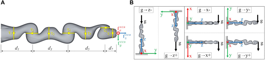
FIGURE 1. (A) The end-effector contact wrenches
2.2 Proprietary Force Estimation Model
A detailed description of the proprietary robot control architecture is given in Albu-Schäffer et al. (2007), Haddadin et al. (2017). For the sake of clarity, the following section discusses essential force control formulations and points out how the proprietary model calculates end-effector contact forces. In the presence of external joint torques due to contact forces, the following dynamics model of robots with flexible joints is considered:
consisting of contact forces
Finally, by including (3) in the general robot dynamics from (1) we can calculate the end-effector contact forces as
2.3 Acquisition of Datasets
The aim of this work is to determine contact wrenches at the end-effector. It is investigated whether the contact wrench can be predicted from corresponding joint positions as well as joint torque data. Different datasets, both simulated and real have been acquired to train and evaluate neural network models.
2.3.1 Simulated Training Data
A large simulated dataset is generated, varying the applied forces, the distances of the end-effector to the force application point as well as the applied external torques for randomized joint configurations. Thus, randomized end-effector contact wrenches are generated and the corresponding joint torques for an ideally static case can be calculated. In our scenario forces between −20 and 20 N are applied at a point with a distance between 0 and 0.15 m to the end-effector. The range results from our application to measure the force acting on an ultrasonic probe attached to the end-effector of a robot. Moreover an additional external torque between −2 and 2 Nm is applied at the end-effector. The steps of generating the simulated training data are explained as follows: Let
By using the transposed geometric Jacobian matrix J(q) of the end-effector we can calculate the corresponding external joint torques according to (3) considering an ideally static case. The simulated dataset consisting of 3,000,000 data points is named datasettrain,sim.
2.3.2 Real Training Data
The aim of this work is to precisely determine corresponding contact wrenches at the end-effector from given joint positions and torque data. Contact wrenches at the end-effector can result from various impacts: by external forces such as pushing or pulling by hand, or while the robot actively pushes against an object with its tool attached to the end-effector. From a mechanical point of view, the resulting wrenches are the same for both cases and can be measured via the joint torques. In this study, the wrenches are simulated by mounting different masses on the end-effector. Gravity produces an equivalent force, which pulls the mass towards the ground. Obviously, this static force will always point in the same direction in the world coordinate system, but for varying robot positions it will create different contact forces in end-effector coordinates. With only one direction in world coordinates not all contact forces can be represented. Hence, six different base rotations were used to solve this problem. The robot was therefore mounted in different orientations, shown in Figure 1B, resulting in a more homogeneous representation of the contact forces in all directions. To determine an exact ground truth for the end-effector forces, specially manufactured calibration weights were used. The weights are built from symmetric metallic discs. By appropriately stacking combinations of these calibration weights on a metallic rod, which was attached to the robots tool flange along the z-axis, we were able to generate 10 equidistantly distributed end-effector forces in 2 N steps in our target range from 0–20 N. The precise total weights resulting from the combinations of stacked calibration weights are mj ∈ {0, 202, 391, 616, 818, 995, 1199, 1401, 1603, 1808, 2002} g, for j ∈ {1 … 11}. Examples of how the calibration weights are stacked on the metallic rod to generate specific end-effector forces are shown in Figure 2. For each mass, 5,000 measurements in newly randomly generated poses were acquired. Thereby sensor hysteresis is part of the data since we approach a multitude of different poses with different combinations of approach directions for each joint. In total a dataset of randomized 330,000 data points with varying base rotations and calibration weights was acquired. The force application point is chosen as the resulting centre of mass of the metallic rod with the appropriately stacked calibration weights. The centers of mass of the corresponding combinations of the metallic rod and the calibration weights are comj ∈ {0, 2.5, 25.5, 28.2, 30.9, 33.4, 38.2, 40.7, 43.2, 42.3, 50} mm, for j ∈ {1 … 11}. These were determined from an accordingly created CAD model in SolidWorks, where the different materials as well as their densities were taken into account.
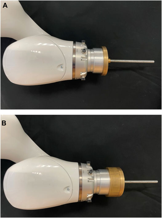
FIGURE 2. Calibration weights were stacked on a metallic rod attached to the end-effector of the robot to generate 10 equidistantly distributed end-effector forces in our target range from 0–20 N. Examples of appropriately stacked calibration weights to generate an end-effector force of 8 N (A) and 18 N (B) are shown.
The exact contact forces for the ground truth can be determined as follows:
For a serial manipulator we can compute the position and orientation of the end-effector by coordinate transformations from the base along the joints by
Using (6) we can also compute the transformation
Let
using homogeneous rotations with six different combinations of the three Euler angles Ψi, Θi and Φi, i ∈ {1 … 6}, denoted in Table 1. Let
Then the forces induced by the calibration masses mj acting in the robot base coordinate system (bcs) can be described by
for i ∈ {1 … 6} and j ∈ {1 … 11}. Now let
with vector t as translational part. We denote
as the end-effector rotation as homogeneous transformation with zero translation in the robot base coordinate frame. Then the forces acting in the end-effector coordinate system (ecs) can be described by
for i ∈ {1 … 6} base rotations, j ∈ {1 … 11} calibration masses and n ∈ {1 … 5,000} measurements.
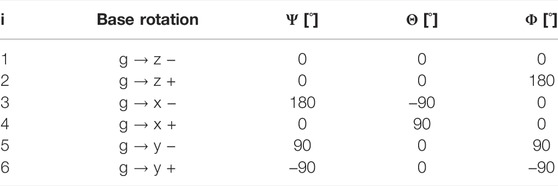
TABLE 1. To calculate the six base transformations
The forces are not acting directly in the end-effector coordinate system, but in the centre of mass of the metallic rod with the appropriately stacked calibration weights. Thus, a moment mecs is generated in the end-effector, which can be calculated by
For every end-effector wrench
for j ∈ {1 … 11} calibration weights. To have a database for the estimation of the gravity torques as well (see Section 2.4), two discrete measurements were performed at each of the randomized positions. First the joint torques without mounted calibration weight τ0 (m0) were recorded. In a second measurement, the torques with mounted calibration τj (mj) were recorded at the very same positions. Collecting the training data required approximately 11 weeks of continuous operation of the robot. This large training dataset consisting of 330,000 randomized positions is named datasettrain, real.
2.3.3 Real Generalisation Testing Data
As described in Section 2.3.2, six different base orientations are used to generate combinations of contact forces. In a realistic scenario, however, these end-effector forces can occur from every direction. Thus, the network must be capable of generalizing intra-directionally. To analyze the directional generalization performance, an additional test dataset was acquired using five varying, unleveled base orientations (see Table 2). Therefore, the manipulator was mounted on a hexapod, as shown in Figure 3. This dataset is only used for evaluating the performance of our models (see Figures 5, 6 in Chapter 3.2)–it is not involved in any form during the training process. Due to the lack of absolute precision of the hexapod, the actually reached Euler angles, for calculating the base orientation (see Section 2.3.3), were measured using an inclinometer with an accuracy of 0.1°. We used a calibration mass of 1.0 kg (10 N). The first dataset was acquired with a known base orientation (zero rotation) as reference. Afterwards the measurements for each orientation were acquired. The dataset is named datasetgen,dir.
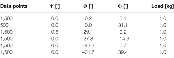
TABLE 2. Base orientations of directional generalization datasetgen,dir.
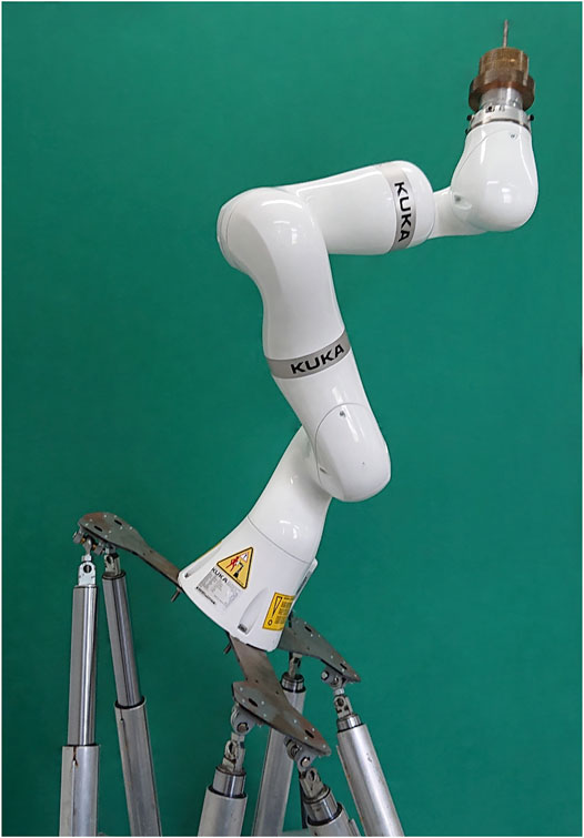
FIGURE 3. The LBR iiwa was mounted on a hexapod to acquire the test data (datasetgen,dir), to evaluate the intra-directional generalization performance.
2.3.4 Real Transfer Testing Data
Generating a large robot specific training dataset as described in Section 2.3.2 is quite time-consuming. To examine the transferability of our approach to another robot type, an additional testing dataset was acquired. This dataset is only used for evaluation purposes (see Figure 7 in Section 3.4), it is not involved during the training process of the neural networks. This transfer testing dataset was acquired with the KUKA iiwa 14 R820. This robot has similar geometric dimensions and thus is well suited for a first experiment/trial. Due to the increased time required as well as the significantly larger self-weight of this robot, which does not allow mounting on our lab wall or lab ceiling, we only generated a dataset in the ground base orientation g → z − (see Figure 1B). For each calibration weight (0.2–20 N) 500 randomized positions are recorded in the same way as described in Section 2.3.2. This results in a dataset of 5,000 positions, which is named datasettransf. The gravity torques τ0 (m0) of the KUKA iiwa 14 R820 are greater than for the smaller KUKA iiwa 7 R800 since the robot links are bigger and heavier. Thus the gravity compensation parameters according to Section 2.4 have to be redetermined for the KUKA iiwa 14 R820, which is done in the same way as described in Section 3.1 using the datasettransf.
2.4 Gravity Torque Compensation Model
For training of the neural network the isolated torques
For a 7-DOF manipulator the relationship between a joint torque τj and the gravity forces Gi acting in the centres of the following links can be shown to be
where
is the linear velocity part of the transposed jacobian for the centre of mass rcom, i of link i. Since we are calculating in the world coordinate system, the force Gi, acting in the centre of mass of link i due to the gravity of mi, is described by
where mi is the mass of link i and g0 is the gravity constant.
Taking into account all of the joints of the manipulator, the following equation system represents the relationship from Eq. 15
Due to (17) the equation system (18) can be simplified since always only the third entry
In order to calculate the gravity torques of a robot according to (19) the masses mi as well as the centers of gravity rcom,i of the links, which are used to calculate
Moreover we replace the unknown link masses mi in (19) by variables wi. These variables wi can be understood as imaginary point masses, which are directly located in the origin of the following joint frame. For example w1 would be the imaginary mass of link 1, located in the origin of joint 2. Replacing mi by wi as well as replacing
This relationship describes the influence of the gravity force of the imaginary masses on the joint torques of the robot. Our goal is to determine fitting imaginary masses wi, located in the origin of the following joints, which have the same influence on the joint torques as the original masses mi located in the center of mass rcom,i of the link. Then approximated gravity joint torques
To determine wi, the equation system in (21) must be solved. This can be done in the least-square sense using N measurements, where N ≫ 7. We selected N = 500 for calculating the optimal linear regression solution
2.5 Neural Network Model for Wrench Prediction
External forces applied to a certain point of an attached tool lead to corresponding contact wrenches at the end-effector. Our aim was the estimation of these wrenches wecs based on the measured joint torques τΔ, the current robot pose and the distance to the force application point, given in the input vector I. This estimation was performed by training a regression model on simulated data for a static case (Section 2.3.1) and retraining it with real training data (Section 2.3.2). We used a dense feed-forward neural network with fully connected layers. The optimal network architecture for our problem has been found by doing a hyperparameter optimization varying the number of layers, the regularizer, the loss function as well as the number of neurons. The neurons were modeled with rectified linear unit (ReLU) activation functions (Nair and Hinton, 2010). The last layer consists of six neurons to predict the wrench vector fecs with linear activation. The activation functions gReLU and glinear are defined as
and
The wrench vector is predicted by propagating the input through the layers of the network (Rumelhart et al. (1986)). The relationship between wecs and the measured joint torques τΔ is highly dependent on the robot’s current joint configuration as well as the distance to the point of force application
Hence, the input I and the output O of the neural network can be written as
The input I was normalized to have zero mean and a unified variance of 1 (zero centering). The model was implemented in Python using Keras (Chollet, 2015) with the Theano-Backend (Theano Development Team, 2016).
2.5.1 Optimal Network Architecture
Firstly, a deep feed forward neural network was trained with the idealized simulated datasettrain,sim. To find an optimal network architecture for our problem of predicting end-effector wrenches, an autonomous hyperparameter optimization was done using the optuna toolbox (Akiba et al., 2019) and the LAMB optimizer (You et al., 2019). In Table 3 the static as well as the varied neural network parameters and their ranges are listed. The loss function for training a particular neural network is an optimization parameter and can vary between mean squared error and mean absolute error (see Table 3). In order to compare the different tested network architectures with an equal metric to find the neural network with the highest prediction accuracy, we calculated a separate evaluation error using the root mean squared error. Training was done on four GPUs of a DGX-2. In total 700 different architectures were tried, which needed a computing time of approximately around 19 days. The resulting optimal neural network model with the highest prediction accuracy is named NNsim. The trained model was used on a regular desktop PC, with an Intel core i7 CPU and a nVidia GeForce GTX 1060. One evaluation step takes 21.5 ms.
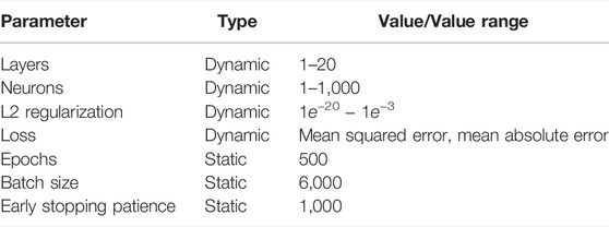
TABLE 3. Hyperparameter optimization - static and dynamic parameters.
2.5.2 Retraining With Real Training Data
The optimized neural network model NNsim resulted from a training process only done with simulated data representing an idealized static case. In a real scenario different inaccuracies like dissipative effects and measurement inaccuracies occur. In addition we do not know the exact isolated torques
To take into account the described inaccuracies, the model based on simulated data NNsim was retrained with the real training dataset datasettrain, real. This was done on a regular desktop PC, with an Intel core i7 CPU and a nVidia GeForce GTX 1060. The resulting model is named NNretrain.
3 Results and Discussion
The goal is to precisely estimate gravity joint torques as well as contact wrenches at the end-effector from given joint positions and torque data. A data-driven method based on linear regression is used to approximate the static gravity torques without any knowledge of the link masses nor the centers of gravity of the links. To estimate the end-effector contact wrench an extensive database, consisting of both simulated and real data, was acquired to develop and evaluate artificial neural network models. For generating real ground truth contact wrenches, ten specially manufactured weights in the range of 0–2 kg (0–20 N) were mounted to the end-effector. By using the constant gravity force and different robot base orientations, a homogeneous representation of contact forces in all directions was realized. Due to various combinations of base orientations, calibration weights and robot poses, the database consists of 330,000 randomized data points. See Section 2.3.2 for more details. For evaluation purposes, the testing datasets (see Section 2.3.3 and Section 2.3.4) were used, which were not included in the training of the neural networks.
Firstly the performance of our proposed gravity compensation model is evaluated in Section 3.1. Afterwards the capabilities of the neural network models to precisely estimate contact wrenches at the end-effector are illustrated (Section 3.2)–even if another robot is used (Section 3.4).
3.1 Accuracy of Gravity Compensation Model
To determine the imaginary masses wi by solving the overdetermined equation system in (21) 500 data points out of the datasettrain, real without mounted calibration weights are used. Increasing the number of data points had not shown any significant change of the results. The datapoints are taken in equal parts from the 6 different base orientations. The optimal solution is (values in N):
By dividing through the negative gravity constant g0, we get
for the imaginary masses wi (values in kg). The result shows, that only the parameters w3, w5 and w7 have values not equal to zero. So in our model the gravity forces acting on the joint torques of the robot are generated only by three imaginary masses. These are located in joint 4 (robot elbow), joint 6 (robot hand) and in the end-effector.
The determined imaginary masses wi are now used to estimate the static gravity torques according to (21). The intra-directionality generalization dataset datasetgen,dir. without mounted calibration weights is used for evaluation. Figure 4 shows the absolute errors for the estimated static gravity torques of the joints using our model. The absolute errors of the estimation of the robots integrated PFEM model are also shown in Figure 4. The robot firmware does not directly output the estimated gravity torques, but the measured joint torques as well as the calculated external joint torques. So for a comparision with our model, the external joint torques are used to calculate the absolute error. For a robot without any weight attached to the endeffector, the external joint torques are lower the better the integrated model of the gravity compensation is. Figure 4 shows that our model fits the zero torques in a static experiment slightly better than the integrated model of the robot manufacturer. Especially the median error of the zero torques for the second joint can be reduced from 1.0 to 0.54 N (46%). Moreover the variability could be reduced, except for joint 5. For joint 5 also the median of the prediction error is 34% higher using our model. Our model seems to have difficulties in estimating the torque in joint 5 induced by the masses of the following links 5, 6 and 7. Theoretically there would be two imaginary masses m5 and m7 unequal to zero, which are located in joint 6 and the end-effector and thus are taken into account for the computation of the joint torque 5. But considering the equation to approximate
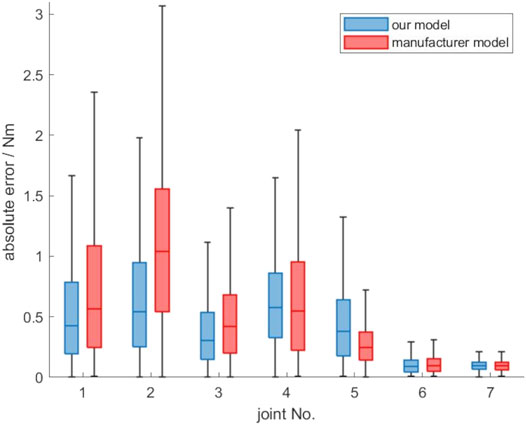
FIGURE 4. Absolute error of the proposed gravity compensation model compared to the model of the robot manufacturer, evaluated on the datasetgen,dir.
The obtained results show the applicability of the presented approach to determine static gravity torques of a robot without knowing the inertial parameters of the links. It represents a simple to implement and time-saving option, since only joint torque data of a few randomly generated poses need to be acquired.
3.2 Accuracy of Contact Wrench Estimation
For evaluation purposes, the contact forces and moments acting at the end-effector are considered separately. The prediction accuracies of the NNsim, which was only trained with the simulated data for an ideal static case and the NNretrain, which was retrained with the real dataset datasettrain, real are compared with the PFEM model.
3.2.1 Optimal Neural Network Architecture
To find the optimal network architecture for the estimation of contact wrenches, an autonomous hyperparameter optimization was done using the optuna toolbox (Akiba et al., 2019) and the LAMB optimizer (You et al., 2019). 700 different architectures were tested. The simulated training dataset was divided into training (95%) and validation data (5%). After 514 iterations the lowest validation error was found for a network architecture, consisting of 14 hidden layers with 681 neurons and a L2 regularization of 1.23e-06. The mean absolute error was used as loss function. The created network is referred to as NNsim. On a regular desktop PC, with an Intel core i7 CPU and a nVidia GeForce GTX 1060, one evaluation step takes 21.5 ms. The evaluation time is thus quite high, which can be explained by the large size of the neural network. Depending on the application, this might have to be taken into account when choosing a network architecture. In our current setup assuming a static scenario, where is no or almost no movement of the robot when the force is estimated, the long evaluation time can be handled. Since we expect slow movements, the reaction time is not extremely critical in this context.
3.2.2 Contact Forces
Figure 5A shows the overall accuracy of our proposed calibration compared to the PFEM based on all measurements of the datasetgen,rob in a linear scale. The absolute error was calculated for the contact forces fecs for each axis separately. The calculation was based on the absolute difference between the ground truth (see Section 2.3.2) and the output of the trained neural network
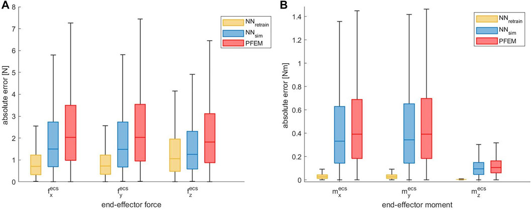
FIGURE 5. (A) Absolute end-effector force error of the ANN approach compared to the PFEM given for each axis in linear scale evaluated on the datasetgen,dir. The median error could be largely reduced by the ANN, which was retrained with real robot data. (B) Absolute end-effector moment error of the ANN approach compared to the PFEM given for each axis in linear scale evaluated on the datasetgen,dir.
3.2.3 Contact Moments
Figure 5B shows the accuracy of our NN models compared to the PFEM. Again the absolute error was calculated for the three axis separately. By using the neural network model NNsim the median absolute error could be slightly reduced by 0.06 Nm (15.1%) for
It must also be noted, that our ground truth for the contact moments is based on the center of mass of the metallic rod with the mounted calibration weights. These were determined from an appropriate created CAD model, so small uncertainties can possibly result. Nevertheless it could be shown, that the relationship between end-effector forces, the distance to the force application point and corresponding end-effector moments can be learned and precisely predicted by the neural network. Due to the problematic issues pointed out regarding the contact moment, in the following chapters the accuracy of contact forces acting at the end-effector is investigated in more detail. These are also of higher relevance for our application of precisely estimating the force acting on an ultrasound probe attached to the robot end-effector.
3.3 Outlier Reduction
As shown in Figure 6A we observed a high number of large outliers in the PFEM data with maximum errors in the range of 104 N. We suspect that these high errors are caused by numerical instabilities of the computational model used by the PFEM near singular configurations. In contrast, our proposed solution provides much more stable results than the integrated model.
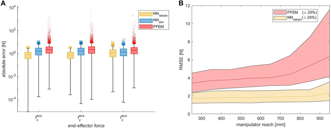
FIGURE 6. (A) Absolute end-effector force error of the ANN approach compared to the PFEM given for each axis in logarithmic scale, evaluated on the datasetgen,dir. The outliers could be largely reduced by the ANN approaches. (B) Contact force RMSE as a function of increasing manipulator reach in linear scale. A strongly rising error can be observed in the PFEM data from a reach above 700 mm.
In order to analyze the problems of incalculable contact forces at singular positions and numerical instabilities close to these positions in more detail, we looked at the contact force errors as a function of the arm position. To acquire this, the manipulators’ reach was used as a relevant parameter. The reach indicates how far the end-effector is displaced from the shoulder. At maximum reach, the arm is therefore fully extended and in a singular configuration. Figure 6B shows the contact force RMSE as a function of increasing reach. With an increasing reach over 700 mm, the error grows dramatically. In addition, the number and magnitude of outliers also rises massively. In contrast, the ANN data shows much more stable results. The outcome indicates that different arm positions have less impact on the model accuracy and, furthermore, that the model is capable of robustly handling singularities. Clearly, this is counterintuitive: Fundamental mathematical laws render contact forces incalculable at singularities since the matrix J from (4) becomes singular. Nevertheless, this does not mean that contact forces in singularities cannot be detected at all, it only means that specific contact forces may not generate torques in all joints, which, in turn, will result in large errors when trying to compute the contact forces. Given that the training data we have collected was generated randomly, it is exceedingly unlikely that the robot was ever moved to an exactly singular position, but rather that it often came close to one. This means that our model has learned to deal with close-to-singular matrices J and, obviously, is capable of adequate compensating. Nevertheless, this does not mean that our model can overcome mathematical impossibilities, it rather means that it is less susceptible to numerical instabilities occurring close to singular positions.
3.4 Transfer to Another Robot
To examine the transferability of our approach to another robot, the accuracy of contact force estimation of the additional testing dataset, which has been acquired with the KUKA iiwa 14 R820, is shown in Figure 7A. By using the neural network model NNsim, which was solely trained on simulated data for the robot geometry of the KUKA iiwa 7 R800, the median absolute error could be slightly reduced by 0.23 N (12.3%) for
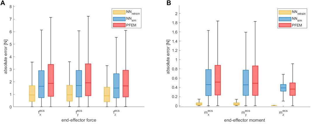
FIGURE 7. Absolute end-effector force error (A) and moment error (B) of the ANN approach compared to the PFEM given for each axis in linear scale, evaluated on the transfer data of the KUKA iiwa 14 R820 datasettransf.
However, it is shown, that the estimation of the contact forces could be improved by our neural network models - even if another robot type is used. Especially the NNretrain can greatly reduce the force prediction errors. Once again it should be emphasized that no additional training data, neither simulated nor real, of the KUKA iiwa 14 R820 were used. Retraining on a small real calibration dataset acquired on this different robot would probably reduce the errors even more so that an accuracy similar to the experiments with the KUKA iiwa 7 R800 in Section 3.2 could be achieved. In this context, it must be noted that our experiments were done on a robot with the same degree of freedom and thus the same size of input data. For a transfer to a robot with a different degree of freedom, the changed size of input data must be taken into account. It might be an option to just replace the input layer of the network for retraining.
4 Conclusion
The aim of this work was to precisely determine corresponding contact wrenches at the end-effector from given joint position and torque data of a redundant serial lightweight manipulator (KUKA LBR iiwa 7 R800). The results of this work show advantages of our proposed neural learning approach compared to the PFEM. Firstly, the new calibration method can increase the accuracy of end-effector contact forces by 57.2% and the accuracy of end-effector contact moments by 90% compared to the manufacturer’s proprietary force estimation model. Secondly, we show that the calibration stability can be significantly increased with the proposed approach. In contrast to the PFEM, which shows high outliers near singularities, the ANN approach shows robust results. The evaluation indicates that different arm positions do not affect the accuracy and, furthermore, the proposed model can robustly handle singularities.
After the promising results of this work, minor limitations remain. The calibration was performed in a limited force range of 0–20 N, which is significantly below the maximum loads of the manipulator. However, compliant robots are often used in specialized practical applications within limited load ranges. Moreover, our results show good generalization performance, even for estimation of the neural network, which was soley trained with simulated data. Thus using a huge simulation dataset with an increased force range and a small real calibration dataset with larger distances between the calibration weights could be used. In addition we plan to further investigate the transferability of our method model to robots from other manufacturers, which have a more different geometry. In this context, a transfer to a robot with a different degree of freedom and thus an input of a different size must also be considered. A robot specific simulated dataset could be generated easily for any robot whose geometric data are known. Afterwards a small number of robot specific new recorded data points could be acquired and used for retraining and thus the prediction performance could be improved.
Data Availability Statement
The raw data supporting the conclusion of this article will be made available by the authors, without undue reservation.
Author Contributions
All authors listed have made a substantial, direct, and intellectual contribution to the work and approved it for publication.
Funding
This study was partially funded by Deutsche Forschungsgemeinschaft (grants ER 817/1–1, ER 817/1-2 and ER 817/4-1) and by the German Federal Ministry of Education and Research (grant 13GW0228 and 01IS19069).
Conflict of Interest
IK was employed by Ibeo Automotive Systems GmbH.
The remaining authors declare that the research was conducted in the absence of any commercial or financial relationships that could be construed as a potential conflict of interest.
Publisher’s Note
All claims expressed in this article are solely those of the authors and do not necessarily represent those of their affiliated organizations, or those of the publisher, the editors and the reviewers. Any product that may be evaluated in this article, or claim that may be made by its manufacturer, is not guaranteed or endorsed by the publisher.
Acknowledgments
We acknowledge financial support by Land Schleswig-Holstein within the funding programme Open Access Publikationfonds.
References
Akiba, T., Sano, S., Yanase, T., Ohta, T., and Koyama, M. (2019). “Optuna: A Next-Generation Hyperparameter Optimization Framework,” in Proceedings of the 25rd ACM SIGKDD International Conference on Knowledge Discovery and Data Mining.
Albu-Schäffer, A., Ott, C., and Hirzinger, G. (2007). A Unified Passivity-Based Control Framework for Position, Torque and Impedance Control of Flexible Joint Robots. Int. J. Robotics Res. 26, 23–39. doi:10.1177/0278364907073776
Bischoff, R., Kurth, J., Schreiber, G., Koeppe, R., Albu-Schaeffer, A., Beyer, A., et al. (2010). “The KUKA-DLR Lightweight Robot Arm - a New Reference Platform for Robotics Research and Manufacturing,” in ISR 2010 (41st International Symposium on Robotics) and ROBOTIK 2010 (6th German Conference on Robotics), 1–8.
Chollet, F. (2015). Keras. [Dataset] https://keras.io.
Gautier, M., and Jubien, A. (2014). “Force Calibration of KUKA LWR-like Robots Including Embedded Joint Torque Sensors and Robot Structure,” in 2014 IEEE/RSJ International Conference on Intelligent Robots and Systems, 416–421. doi:10.1109/IROS.2014.6942593
Haddadin, S., De Luca, A., and Albu-Schäffer, A. (2017). Robot Collisions: A Survey on Detection, Isolation, and Identification. IEEE Trans. Robot. 33, 1292–1312. doi:10.1109/tro.2017.2723903
Hai-Long Pei, H.-L., Qi-Jie Zhou, Q.-J., and Leung, T. P. (1992). “A Neural Network Robot Force Controller,” in Proceedings of the IEEE/RSJ International Conference on Intelligent Robots and Systems, 3 1974–1979. doi:10.1109/IROS.1992.601929
Hollerbach, J., Khalil, W., and Gautier, M. (2008). Model Identification. Berlin, Heidelberg: Springer Berlin Heidelberg, 321–344. doi:10.1007/978-3-540-30301-5_15
Jung, S., Yim, S. B., and Hsia, T. C. (2001). “Experimental Studies of Neural Network Impedance Force Control for Robot Manipulators,” in Proceedings 2001 ICRA. IEEE International Conference on Robotics and Automation (Cat. No.01CH37164), 4 3453–3458.
Khatib, O. (1987). A Unified Approach for Motion and Force Control of Robot Manipulators: The Operational Space Formulation. IEEE J. Robot. Automat. 3, 43–53. doi:10.1109/jra.1987.1087068
Khosla, P., and Kanade, T. (1985). “Parameter Identification of Robot Dynamics,” in 1985 24th IEEE Conference on Decision and Control, 1754–1760. doi:10.1109/CDC.1985.268838
Kružić, S., Musić, J., Kamnik, R., and Papić, V. (2021). End-effector Force and Joint Torque Estimation of a 7-dof Robotic Manipulator Using Deep Learning. Electronics 10, 2963. doi:10.3390/electronics10232963
Kumar, N., Panwar, V., Sukavanam, N., Sharma, S. P., and Borm, J.-H. (2011b). Neural Network Based Hybrid Force/position Control for Robot Manipulators. Int. J. Precis. Eng. Manuf. 12, 419–426. doi:10.1007/s12541-011-0054-3
Kumar, N., Panwar, V., Sukavanam, N., Sharma, S. P., and Borm, J. H. (2011a). Neural Network-Based Nonlinear Tracking Control of Kinematically Redundant Robot Manipulators. Math. Comp. Model. 53, 1889–1901. doi:10.1016/j.mcm.2011.01.014
Li, S., Zhang, Y., and Jin, L. (2017). Kinematic Control of Redundant Manipulators Using Neural Networks. IEEE Trans. Neural Netw. Learn. Syst. 28, 2243–2254. doi:10.1109/tnnls.2016.2574363
Lian, R.-J. (2014). Adaptive Self-Organizing Fuzzy Sliding-Mode Radial Basis-Function Neural-Network Controller for Robotic Systems. IEEE Trans. Ind. Electron. 61, 1493–1503. doi:10.1109/tie.2013.2258299
Lu, T.-F., Lin, G. C. I., and He, J. R. (1997). Neural-network-based 3D Force/torque Sensor Calibration for Robot Applications. Eng. Appl. Artif. Intelligence 10, 87–97. doi:10.1016/S0952-1976(96)00069-3
Lutter, M., Ritter, C., and Peters, J. (2019). Deep Lagrangian Networks: Using Physics as Model Prior for Deep Learning, 04490. CoRR abs/1907.
Maciejewski, A. A. (1991). Kinetic Limitations on the Use of Redundancy in Robotic Manipulators. IEEE Trans. Robot. Automat. 7, 205–210. doi:10.1109/70.75903
Nair, V., and Hinton, G. E. (2010). “Rectified Linear Units Improve Restricted Boltzmann Machines,” in Proceedings of the 27th international conference on machine learning (ICML-10), 807–814.
Raj, D. R., Raglend, I. J., and Anand, M. D. (2015). “Inverse Kinematics Solution of a Five Joint Robot Using Feed Forward and Elman Network,” in Circuit, Power and Computing Technologies (ICCPCT), 2015 International Conference on (IEEE), 1–5. doi:10.1109/iccpct.2015.7159376
Rumelhart, D. E., Hinton, G. E., and Williams, R. J. (1986). Learning Representations by Back-Propagating Errors. Nature 323, 533–536. doi:10.1038/323533a0
Sadjadian, H., Taghirad, H., and Fatehi, A. (2005). Neural Networks Approaches for Computing the Forward Kinematics of a Redundant Parallel Manipulator. Int. J. Comput. Intelligence 2, 40–47.
Schreiber, G., Stemmer, A., and Bischoff, R. (2010). “The Fast Research Interface for the KUKA Lightweight Robot,” in Workshop on IEEE ICRA 2010 Workshop on Innovative Robot Control Architectures for Demanding (Research) Applications - How to Modify and Enhance Commercial Controllers, 15–21.
Schweikard, A., and Ernst, F. (2015). Medical Robotics. Springer, 339–346. chap. Joint Torques and Jacobi-Matrices.
Smith, A. C., Mobasser, F., and Hashtrudi-Zaad, K. (2006). Neural-Network-Based Contact Force Observers for Haptic Applications. IEEE Trans. Robot. 22, 1163–1175. doi:10.1109/tro.2006.882923
Theano Development Team (2016). Theano: A Python Framework for Fast Computation of Mathematical Expressions.arXiv e-prints abs/1605.02688.
Wang, S., Shao, X., Yang, L., and Liu, N. (2020). Deep Learning Aided Dynamic Parameter Identification of 6-dof Robot Manipulators. IEEE Access 8, 138102–138116. doi:10.1109/ACCESS.2020.3012196
You, Y., Li, J., Hseu, J., Song, X., Demmel, J., and Hsieh, C. (2019). Reducing BERT Pre-training Time from 3 Days to 76 minutesCoRR Abs/1904, 00962.
Keywords: deep learning, force estimation, wrench estimation, robotic manipulator, artificial neural network
Citation: Osburg J, Kuhlemann I, Hagenah J and Ernst F (2022) Using Deep Neural Networks to Improve Contact Wrench Estimation of Serial Robotic Manipulators in Static Tasks. Front. Robot. AI 9:892916. doi: 10.3389/frobt.2022.892916
Received: 09 March 2022; Accepted: 08 April 2022;
Published: 28 April 2022.
Edited by:
Yanan Li, University of Sussex, United KingdomReviewed by:
Yiming Fei, Harbin Institute of Technology, ChinaStanko Kružić, University of Split, Croatia
Copyright © 2022 Osburg, Kuhlemann, Hagenah and Ernst. This is an open-access article distributed under the terms of the Creative Commons Attribution License (CC BY). The use, distribution or reproduction in other forums is permitted, provided the original author(s) and the copyright owner(s) are credited and that the original publication in this journal is cited, in accordance with accepted academic practice. No use, distribution or reproduction is permitted which does not comply with these terms.
*Correspondence: Jonas Osburg, osburg@rob.uni-luebeck.de
†These authors have contributed equally to this work and share first authorship
‡Present address: Ivo Kuhlemann, Ibeo Automotive Systems GmbH, Hamburg, Germany