Leveraging pleat folds and soft compliant elements in inflatable fabric beams
 Juan J. Huaroto
 Etsel Suarez1
  Emir A. Vela
- 1Department of Mechanical Engineering, Universidad Nacional de Ingenieria, Lima, Peru
- 2Department of Mechanical Engineering, Universidad de Ingenieria y Tecnologia—UTEC, Lima, Peru
- 3Research Center in Bioengineering, Universidad de Ingenieria y Tecnologia—UTEC, Lima, Peru
Inflatable fabric beams (IFBs) integrating pleat folds can generate complex motion by modifying the pleat characteristics (e.g., dimensions, orientations). However, the capability of the IFB to return to the folded configuration relies upon the elasticity of the fabrics, requiring additional pressure inputs or complementary mechanisms. Using soft compliant elements (SCEs) assembled onto pleat folds is an appealing approach to improving the IFB elasticity and providing a range of spatial configurations when pressurized. This study introduces an actuator comprising an IFB with pleat folds and SCEs. By methodologically assembling the SCEs onto the pleat folds, we constrain the IFB unfolding to achieve out-of-plane motion at 5 kPa. Besides, the proposed actuator can generate angular displacement by regulating the input pressure (
1 Introduction
The field of soft robotics has opened up new avenues to design and fabricate actuators, sensors, and mechanisms (Yasa et al., 2023). During the last decade, various actuation principles (e.g., pneumatic (Xavier et al., 2022), dielectric (Gupta et al., 2019), magnetorheological (Bastola et al., 2020), magnetic (Kim and Zhao, 2022)) have motivated the development of soft actuators for a myriad of applications, ranging from aerospace to physiatry (Huaroto et al., 2019; Yoo et al., 2019; Gollob et al., 2023; O’Neill et al., 2023; Zhang et al., 2023a). In particular, soft pneumatic actuators have been the gold standard for creating large stroke actuation. However, bulk structures made of rubber-like silicones have limited the practical integration of soft pneumatic actuators in wearable devices (Zhu et al., 2020; Yang et al., 2023). Fabric-based pneumatic actuators (FPAs) harness the properties of fabrics (e.g., light weight, flexibility, anisotropy, and softness) to enable their integration into wearable devices (Suarez et al., 2018; Connolly et al., 2019; Yoo et al., 2019; O’Neill et al., 2021), smart garments (Sanchez et al., 2021), and systems for assistive technology or human augmentation (Cappello et al., 2018a; Liang et al., 2018; Proietti et al., 2023).
The FPAs frequently use knit and woven textiles to fabricate fundamental structures such as pouches and inflatable fabric beams (IFBs) (Niiyama et al., 2015; Khin et al., 2017; Yoo et al., 2019; Nguyen and Zhang, 2020; Lee and Rodrigue, 2023). These inflatable structures are engineered to create twisting, elongating, bending, straightening, and multi-degrees-of-freedom actuators (Nguyen and Zhang, 2020; Sanchez et al., 2021. In particular, an IFB can attain a targeted motion through the incorporation of tailored sewing patterns (Yap et al., 2017a; Ge et al., 2020; Zhu et al., 2020; Suulker et al., 2022), heat-sealing hinges (Ou et al., 2016; Khin et al., 2017), anisotropic fabrics (Cappello et al., 2018b; Connolly et al., 2019), and folds (Yoo et al., 2019). While IFBs have found applications in manipulators, grippers, and assistive technology, their ability to revert to the folded configuration upon depressurization relies upon the elasticity modulus of the fabric (Nesler et al., 2018; Yoo et al., 2019). The textiles used in IFBs possess a notably higher elasticity modulus than elastomeric materials (Zhang et al., 2023b). This characteristic facilitates a swift and stable inflation response of the IFBs but limits their ability to revert to their original state. Prior research has addressed this challenge by integrating supplementary bladders along with pressure inputs (Cappello et al., 2018a), winding mechanisms (Zhang et al., 2023b), and elastomeric materials (i.e., soft compliant elements) (Natividad et al., 2017; Suarez et al., 2018).
In the realm of IFBs integrating folds, pleating techniques have motivated the development of straightening and bending actuators (Khin et al., 2017; Nesler et al., 2018; Yoo et al., 2019). A pleat fold is a fundamental origami fold consisting of valley and mountain creases. Incorporating pleat folds into an IFB serves as a method to develop deployable structures, enabling programmable motion by setting the distances between creases (Yap et al., 2017a; Yoo et al., 2019). In order to revert the IFB to its folded configuration, an appealing approach consists of integrating soft compliant elements (SCEs) onto pleat fold creases. However, this integration represents an unexplored domain in the state-of-the-art (Yoo et al., 2019). The SCEs can constrain the inherent tendency of the IFB to straighten under pressure to perform out-of-plane motion and a range of spatial configurations at varying pressure inputs. In addition, the inherent elasticity of SCEs can revert the IFB to its folded configuration upon deactivating the input pressure. Exploring the influence of geometrical characteristics of SCEs, fold dimensions, and their integration can provide insights into the IFB motion, enabling potential applications in inflatable manipulators and soft wearable devices.
In this study, we combine the benefits of using fabric and elastomeric materials to introduce an actuator that incorporates an IFB with pleat folds and SCEs. By strategically assembling the SCEs onto the pleat folds, we enable out-of-plane motion at 5 kPa and angular displacement at varying pressures (
2 Materials and methods
2.1 Design concept
In order to elucidate the design concept of the proposed actuator, we consider an inflatable fabric beam (IFB) with a single pleat fold. The pleat fold comprises the following creases: valley and mountain, which are represented by the alphabet “v” and “m”, respectively (Figure 1A). The folded IFB is assembled with a soft-compliant element (SCE) of 2 mm thick, which constrains the IFB motion when pressurized. Figure 1B shows that the creases act as pivots when input pressure is activated. As a result, we divide the motion of the proposed actuator into two steps. (1) Input pressure (0–5 kPa): The actuator unfolds with respect to the crease (m), achieving the maximum vertical deployment at ≈ 5 kPa. (2) Input pressure (
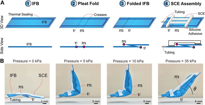
FIGURE 1. (A) Design concept and illustration of the proposed actuator. ① Inflatable fabric beam (IFB). ② Generation of a pleat fold comprising valley (v) and mountain (m) creases. ③ Folded IFB. ④ Assembly of a soft compliant element (SCE) onto the pleat fold. (B) Image frames of the actuator motion. The actuator is initially folded and deploys with respect to the crease (m) when powered by input pressure. The actuator achieves the maximum vertical deployment at 5 kPa. The increase in pressure leads to control of the angular displacement (θ) of the actuator with respect to the crease (v).
2.2 Structural analysis of SCEs
The angular displacement (θ) of the actuator can be programmed by varying the stiffness of the SCE. Figure 2A shows the dimensions of the SCEs. The white parts (w × c × b mm3) are the segments used to glue the SCE on the IFB, while the gray part (w × h × b mm3) contains the shape of the SCE. In this study, we propose four geometries: Two based on topological optimization (TO1 and TO2) and two others using honeycomb unit cells (HC1 and HC2) (Figure 2A). The SCEs based on topological optimization are obtained using Ansys (version 18.0, Ansys Inc., United States). A solid rectangular plate with dimensions (30 × 30 × 2 mm3) is bounded by one of its sides while a force is applied on the opposite side. For obtaining the shapes TO1 and TO2, axial and transversal forces of 2 N magnitude are used. The objective function is established to maximize the deformation while keeping 25% of the plate volume. The resulting geometries are imported to SolidWorks (version 2018 SP5, SolidWorks Corp., United States) for processing. The shapes HC1 and HC2 are obtained using honeycomb unit cells characterized by angles of 45° and 60°, respectively (Figure 2A). To compare the structural stiffness of each SCE, we perform simulations in Ansys (version 18.0, Ansys Inc., United States). Figures 2B, C show the axial and transversal displacement for a range of axial (Fa) and transversal (Ft) forces applied at the tip of the SCE. A commercial rubber-like material (RTV-1520) is used in the simulations and, subsequently, the fabrication of the SCEs. The material is characterized by a 3-parameters (C10 = −1138 kPa, C01 = 1389 kPa, and C11 = 569 kPa) Mooney-Rivlin hyperelastic model obtained from a hyperelastic uniaxial test (ASTM D412 “Tensile Strength Properties of Rubber and Elastomers”) (Suarez et al., 2018). The simulation results reveal the higher stiffness of TO1 and TO2 compared to HC1 and HC2 for axial and transversal deformations.
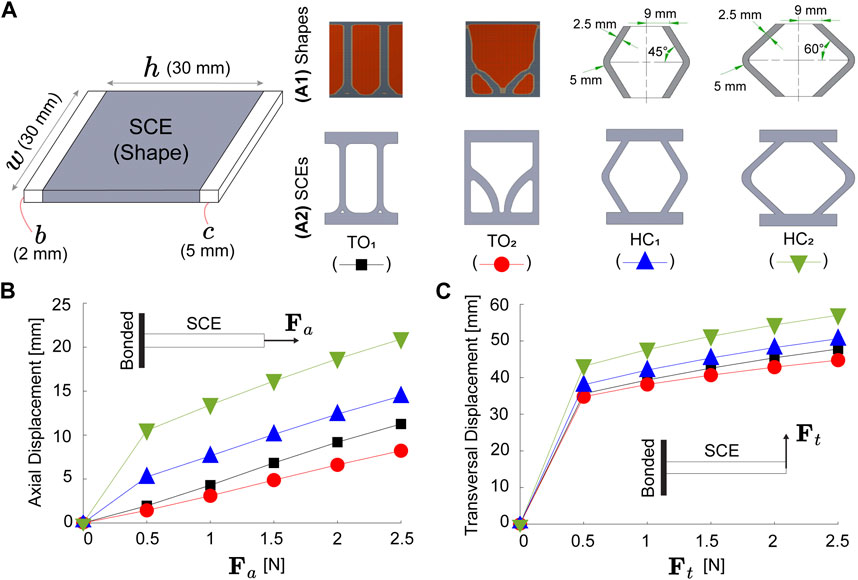
FIGURE 2. Four proposed soft compliant elements (SCEs). (A) Dimensions, (A1) shapes, and (A2) illustrations. The SCEs are based on topological optimization (TO1 and TO2) and honeycomb cells (HC1 and HC2). Finite element simulations of SCEs under (B) axial (Fa) and (C) transversal (Ft) forces.
2.3 Fabrication of components and assembly
The IFB is manufactured by cutting two sheets (w × l mm2) of thermoplastic polyurethane fabric (Heat Sealable 200 Denier Oxford Nylon, Rockywoods Fabrics, United States). These sheets are placed one over another and then sealed with a thermosealing machine (FS-200, HUALIAN America S.A., Mexico). The thermosealing has an offset (e) in millimeters with respect to the fabric edges (Figure 3A). A connecting tube is integrated with one of the ends of the IFB using instant adhesive (Loctite 401, Henkel AG and Co. KGaA, Germany). The pleat folds are manually made on the IFB using heat and pressure. The SCEs are fabricated by curing RTV-1520 silicone rubber in 3D printed (MD-6C, Shenzhen Mingda Technology Co., China) Polylactic acid (PLA) molds. The RTV-1520 components are mixed (1:1 mass ratio) and subsequently poured into the molds. Thereon, the molds containing the blend are put into a vacuum chamber and cured at room temperature for 6 h. The resulting SCEs are glued on the IFB using silicone adhesive (Sil-Poxy, SmoothOn Inc., United States).
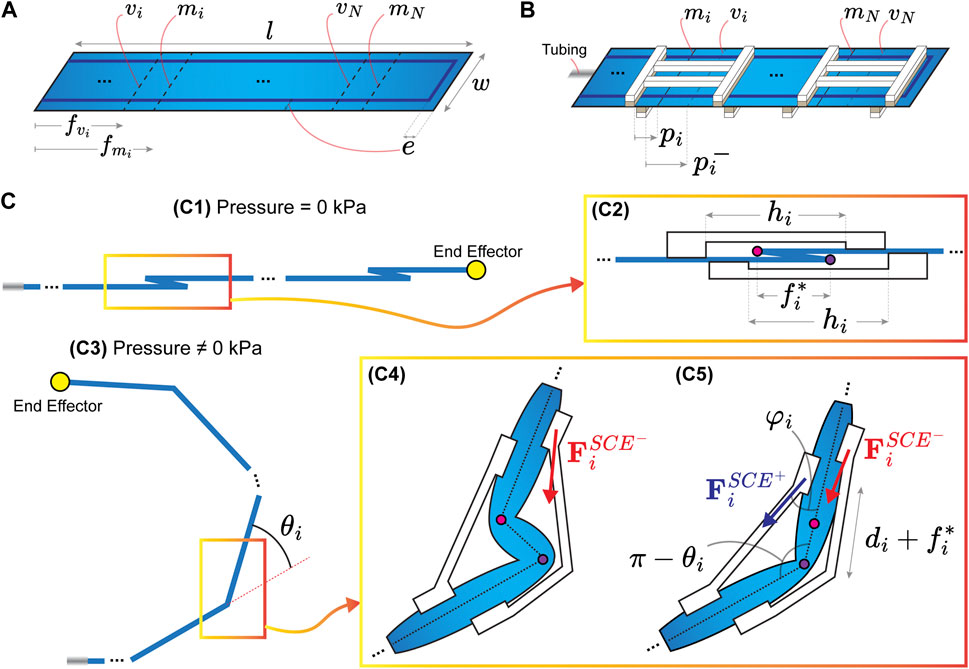
FIGURE 3. (A) Inflatable fabric structure (IFB) with dimensions w × l mm2 and N pleat folds. The thermosealing of the IFB has an offset (e) with respect to the fabric edges. The ith pleat fold is composed of two creases (vi and mi), where i =1,2,… , N. The distances (
2.4 Matrix-based representation
The design concept of an IFB, including a pleat fold and an SCE, provides the fundamental working principle of the proposed actuator. Aiming to provide a general and structured formulation of the IFB, pleat folds, and SCEs geometry, we present a matrix-based representation of the proposed actuator. We consider an IFB (w × l mm2) on which the thermosealing has an offset (e) with respect to the fabric edges (Figure 3A). The IFB has
Using the columns of (F) we define the fold dimension
Following the matrix-based representation, the characteristics of SCEs are integrated into the matrix
the symbol (□) indicates the type of the SCE (TO1, TO2, HC1, and HC2). The proposed actuator integrates the matrices (P, F, and S), which contain the main parameters to describe the actuator mathematically. We define the matrix
2.5 Modeling
In order to complement the matrix-based representation of the actuator, we present a forward kinematics model based on the associated energy of the folds
Where
Where the superscripts (+, −) indicate the position (top and underneath) of the SCE. Besides, I1, I2, and I3 are the principal invariants of the Cauchy - Green tensor. Each invariant is defined using the principal stretch ratios λ1, λ2, and λ3 (with 1, 2, and 3 as the principal axes). The following equations define the principal invariants:
Using Eq. (6), the equation to compute the total deformation energy per unit of volume
In order to simplify the model, we assume only the axial deformation ratio in the SCEs (see Figure 3(C5)). Therefore, we approximate λ2 ≈ 1 (since the SCEs do not bend significantly about its axial axis), hence λ1 = λ and
Where
It is worth noting that the torque caused by force
Where
Where r is the approximated cross-sectional radius of the IFB when pressurized. By differentiating the total energy with respect to θi, we obtain the following equation:
Solving 15 by substituting Eqs (6)–(14) permits to obtain the angles (θi) at a given pressure P. The resulting angles are used to determine the forward kinematic model of the proposed actuator. Figure 3(C1) and (C3) are the initial and deployed positions of the IFB, respectively. Using 2, we obtain the initial position
where
2.6 Instrumentation
The actuator is powered using a pressurized air source controlled by a pressure regulator (P31R Series, Parker Hannifin Corp., United States). We measure the pressure supplied to the actuator using a sensor (ASDX 100PGAA5, Honeywell International Inc., United States). The pressure sensor is connected to an analog-to-digital converter (Arduino Uno, Arduino, Italy), which communicates to a computer through a USB 3.0 interface (10 kHz sampling frequency). A camera (Hero 6, GoPro, United States) records images and videos of the actuator in response to applied internal pressure. For static experiments, the images are acquired in the field of view 2040 × 2040 pixels. The experimental results for the angular displacement are averaged over 3 datasets. A custom script of MATLAB (version 2017, MathWorks, United States) is employed to obtain the angular displacement (θ1) (Figures 4A–D). The camera records videos in the field of view 1920 × 1080 pixels for dynamic experiments using a maximum frame rate of 120 frames per second (fps). The vertical displacement (YT) achieved by the actuator is obtained through a custom script of MATLAB (Figure 4E).
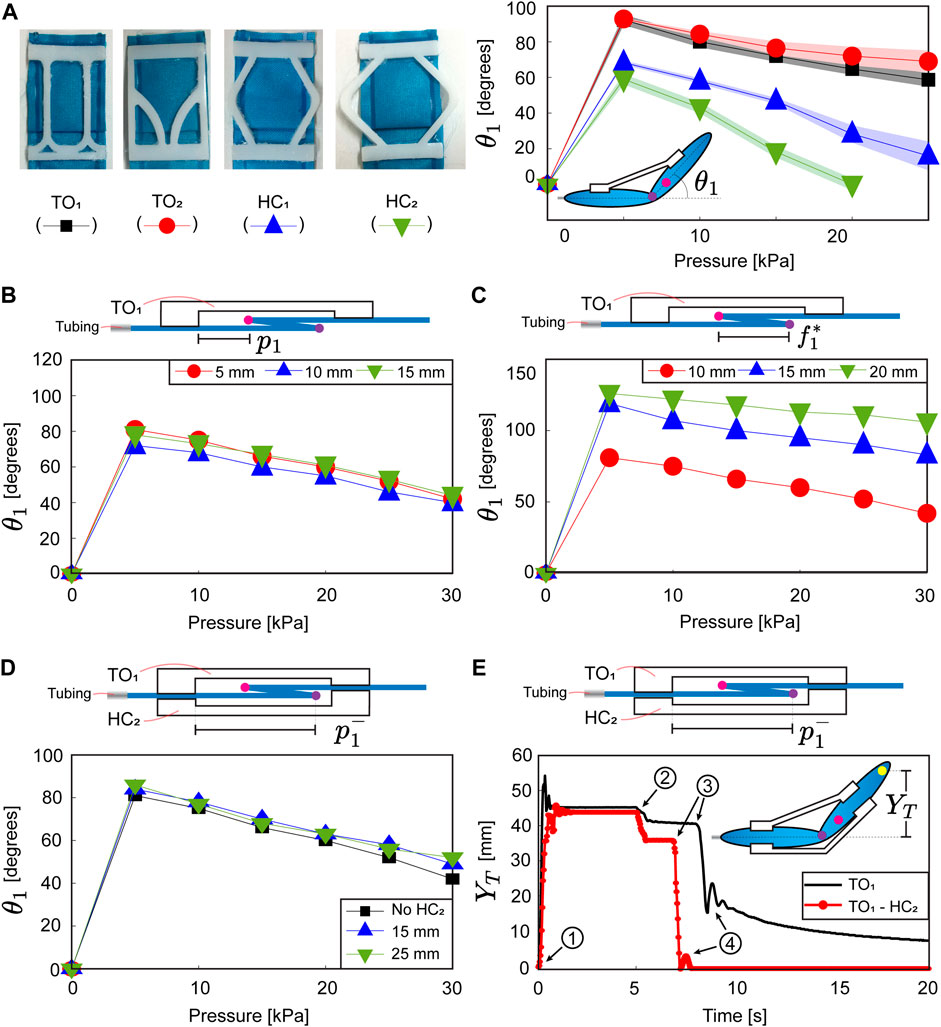
FIGURE 4. (A) Four actuators using the proposed soft compliant elements (SCEs) and angular displacement (θ1) for a set of pressure inputs. Angular displacement at varying (B) assembly distances (p1) and (C) fold lengths
The force characterization is carried out using a load cell (CZL635, Phidgets Inc., Canada) fixed on a 3D-printed structure (Figure 5A). The actuator is located and secured on the 3D-printed structure for analysis. The pressure pumped through the actuator is measured using the setup previously described to analyze the actuator motion. Aiming to acquire the unfolding forces produced by the actuator, we set a gap (≈10 mm) between the load cell and IFB (Figure 5A). The analog signals acquired from the load cell are transmitted to a Wheatstone bridge amplifier (Bridge 4-Input, Phidgets Inc., Canada), which is connected to a computer using a USB 3.0 interface (sampling frequency of 125 Hz). The data acquired are processed, averaged over 3 datasets, and displayed in a Python interface (version 2.7.1).
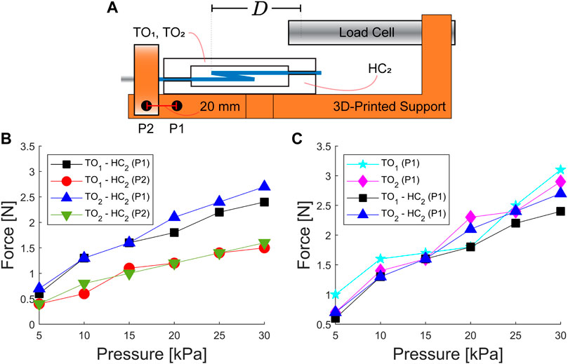
FIGURE 5. Unfolding force characterization. (A) Illustration of the experimental setup utilized to acquire the force exerted by the actuators. The points (P1 and P2) are used to vary the relative distance (D) between the actuator crease (m) and the load cell tip. (B) Unfolding force obtained for two types of actuators (TO1–HC2 and TO2–HC2) using the two positions (P1 and P2). (C) Folding force of actuators using a single SCE (TO1 and TO2) and two SCEs (TO1–HC2 and TO2–HC2) at the position (P1).
3 Results
In this section, we analyze the actuator motion and unfolding force at varying pressure inputs. Besides, we test the assembly of two SCEs onto the pleat fold to explore the actuator’s capability to return to its folded configuration when depressurized. Two experimental proofs-of-concept are devised and conducted to validate the capabilities of the proposed actuator. (1) A planar serial manipulator. (2) A gripper with two grasping modalities.
3.1 Angular displacement
We commence our analysis by experimentally obtaining the angular displacement of an actuator using the proposed SCEs (TO1, TO2, HC1, HC2) (Figure 4A). We fabricate an IBF (P = [30, 100, 5]T) with a single pleat fold (
3.2 Actuator with two SCEs
The analysis of the angular displacement using a single SCE demonstrates that the actuator motion can be programmed by selecting the axial stiffness of the SCE and varying the fold length. Here, we study the effect of using two SCEs (glued on top and underneath the pleat fold). For the analysis, we use the previously fabricated IFB (P = [30, 100, 5]T) with a single pleat fold (
The previous result demonstrates that the additional SCE does not contribute to the angular displacement of the actuator at the static equilibrium. Aiming to explore the dynamic effects of the additional SCE, we experimentally study the actuator response for a pressure pulse of 15 kPa. Two actuators (one with a single SCE and the other with two SCE) are fabricated to compare their dynamic response. To this end, we use the following characteristics: IFB dimensions (P = [30, 100, 5]T), fold length (
3.3 Force
Understanding the static/dynamic behavior of the proposed actuator permits tuning the angular displacement and facilitating the actuator to return to the folded configuration. Here, we expand our study to analyze the unfolding force generated at varying input pressure. Previous analysis using the illustration in Figure 3(C4) has demonstrated that the force
3.4 Experimental proof-of-concept
In order to demonstrate the versatility of the proposed actuator, we propose two demonstrations. (1) A planar serial manipulator. (2) A gripper with two grasping modalities. For the first demonstration, we develop two manipulators, each comprising of an IFB equipped with two and three joints (i.e., pleat folds), respectively. On each joint, two SCEs are integrated following the matrix-based representations:
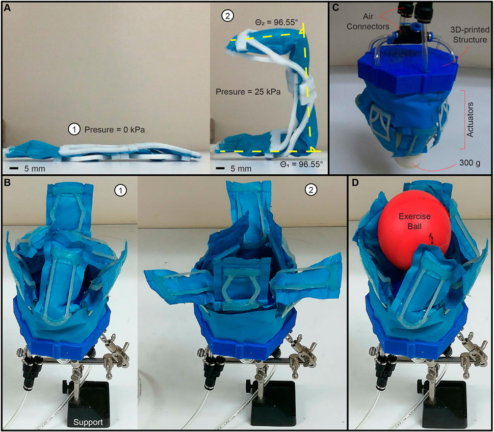
FIGURE 6. Experimental proof-of-concept. (A) Planar serial manipulator using an Inflatable fabric beam (IFB) with two joints (i.e., pleat folds) equipped with four soft compliant elements (SCEs). ① Folded configuration.② deployed condition. The dashed and yellow lines represent the manipulator angles obtained numerically (details in Supplementary Figure S1). (B) Gripper composed of six actuators. ① grasping modality 1. ② grasping modality 2. (C) Gripper used for lifting an object of 300 g. (D) Gripper grasping a hand exercise ball (using modality 1). Please refer to the accompanying video for the demonstration of all experimental proofs-of-concept.
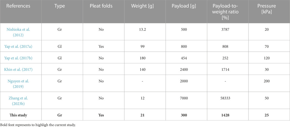
TABLE 1. Comparison of developed gripper with existing fabric-based pneumatic grippers (Gr) and gloves (Gl).
4 Discussion
In summary, we introduce an actuator comprising an inflatable fabric beam (IFB) with pleat folds and soft compliant elements (SCEs). Integrating SCEs with pleat folds permits a range of spatial configurations. Besides, it contributes to facilitating the return of the IFB to the folded state. The proposed actuator has a maximum thickness of 4 mm and achieves the maximum vertical deployment at 5 kPa. The increase in pressure (
Data availability statement
The original contributions presented in the study are included in the article/Supplementary Material, further inquiries can be directed to the corresponding authors.
Author contributions
JH: Conceptualization, Data curation, Formal Analysis, Software, Validation, Writing–original draft, Writing–review and editing. ES: Writing–review and editing. WK: Writing–review and editing. EV: Funding acquisition, Supervision, Writing–review and editing.
Funding
The author(s) declare financial support was received for the research, authorship, and/or publication of this article. This work is supported by FONDECYT Peru under contract No. 105-2021-FONDECYT Proyectos de Investigación Aplicada y Desarrollo Tecnológico.
Conflict of interest
The authors declare that the research was conducted in the absence of any commercial or financial relationships that could be construed as a potential conflict of interest.
Publisher’s note
All claims expressed in this article are solely those of the authors and do not necessarily represent those of their affiliated organizations, or those of the publisher, the editors and the reviewers. Any product that may be evaluated in this article, or claim that may be made by its manufacturer, is not guaranteed or endorsed by the publisher.
Supplementary material
The Supplementary Material for this article can be found online at: https://www.frontiersin.org/articles/10.3389/frobt.2023.1267642/full#supplementary-material
References
Bastola, A. K., Paudel, M., Li, L., and Li, W. (2020). Recent progress of magnetorheological elastomers: a review. Smart Mater. Struct. 29, 123002. doi:10.1088/1361-665x/abbc77
Cappello, L., Galloway, K. C., Sanan, S., Wagner, D. A., Granberry, R., Engelhardt, S., et al. (2018a). Exploiting textile mechanical anisotropy for fabric-based pneumatic actuators. Soft Robot. 5, 662–674. doi:10.1089/soro.2017.0076
Cappello, L., Meyer, J. T., Galloway, K. C., Peisner, J. D., Granberry, R., Wagner, D. A., et al. (2018b). Assisting hand function after spinal cord injury with a fabric-based soft robotic glove. J. Neuroengineering Rehabilitation 15, 59. doi:10.1186/s12984-018-0391-x
Connolly, F., Wagner, D. A., Walsh, C. J., and Bertoldi, K. (2019). Sew-free anisotropic textile composites for rapid design and manufacturing of soft wearable robots. Extreme Mech. Lett. 27, 52–58. doi:10.1016/j.eml.2019.01.007
Ge, L., Chen, F., Wang, D., Zhang, Y., Han, D., Wang, T., et al. (2020). Design, modeling, and evaluation of fabric-based pneumatic actuators for soft wearable assistive gloves. Soft Robot. 7, 583–596. doi:10.1089/soro.2019.0105
Gollob, S. D., Mendoza, M. J., Koo, B. H. B., Centeno, E., Vela, E. A., and Roche, E. T. (2023). A length-adjustable vacuum-powered artificial muscle for wearable physiotherapy assistance in infants. Front. Robotics AI 10, 1190387. doi:10.3389/frobt.2023.1190387
Gupta, U., Qin, L., Wang, Y., Godaba, H., and Zhu, J. (2019). Soft robots based on dielectric elastomer actuators: a review. Smart Mater. Struct. 28, 103002. doi:10.1088/1361-665x/ab3a77
Huaroto, J. J., Suarez, E., Krebs, H. I., Marasco, P. D., and Vela, E. A. (2019). A soft pneumatic actuator as a haptic wearable device for upper limb amputees: toward a soft robotic liner. IEEE Robotics Automation Lett. 4, 17–24. doi:10.1109/lra.2018.2874379
Khin, P. M., Yap, H. K., Ang, M. H., and Yeow, C. (2017). “Fabric-based actuator modules for building soft pneumatic structures with high payload-to-weight ratio,” in Procedings of the 2017 IEEE/RSJ international conference on intelligent robots and systems (IROS), 2744–2750.
Kim, Y., and Zhao, X. (2022). Magnetic soft materials and robots. Chem. Rev. 122, 5317–5364. doi:10.1021/acs.chemrev.1c00481
Lee, H., and Rodrigue, H. (2023). Harnessing the nonlinear properties of buckling inflatable tubes for complex robotic behaviors. Mater. Today 63, 59–88. doi:10.1016/j.mattod.2023.02.005
Liang, X., Cheong, H., Sun, Y., Guo, J., Chui, C. K., and Yeow, C.-H. (2018). Design, characterization, and implementation of a two-dof fabric-based soft robotic arm. IEEE Robotics Automation Lett. 3, 2702–2709. doi:10.1109/lra.2018.2831723
Natividad, R. F., Del Rosario, M. R., Chen, P. C. Y., and Yeow, C. (2017). “A hybrid plastic-fabric soft bending actuator with reconfigurable bending profiles,” in 2017 IEEE international conference on robotics and automation (ICRA), 6700–6705.
Nesler, C. R., Swift, T. A., and Rouse, E. J. (2018). Initial design and experimental evaluation of a pneumatic interference actuator. Soft Robot. 5, 138–148. doi:10.1089/soro.2017.0004
Nguyen, P. H., Sridar, S., Amatya, S., Thalman, C. M., and Polygerinos, P. (2019). “Fabric-based soft grippers capable of selective distributed bending for assistance of daily living tasks,” in 2019 2nd IEEE international conference on soft robotics (RoboSoft) (IEEE), 404–409.
Nguyen, P. H., and Zhang, W. (2020). Design and computational modeling of fabric soft pneumatic actuators for wearable assistive devices. Sci. Rep. 10, 9638. doi:10.1038/s41598-020-65003-2
Niiyama, R., Sun, X., Sung, C., An, B., Rus, D., and Kim, S. (2015). Pouch motors: printable soft actuators integrated with computational design. Soft Robot. 2, 59–70. doi:10.1089/soro.2014.0023
Nishioka, Y., Uesu, M., Tsuboi, H., and Kawamura, S. (2012). “Proposal of an extremely lightweight soft actuator using plastic films with a pleated structure,” in 2012 19th international conference on mechatronics and machine vision in practice (M2VIP) (IEEE), 474–479.
O’Neill, C. T., McCann, C. M., Hohimer, C. J., Bertoldi, K., and Walsh, C. J. (2021). Unfolding textile-based pneumatic actuators for wearable applications. Soft Robot. 9, 163–172. doi:10.1089/soro.2020.0064
O’Neill, C. T., Young, H. T., Hohimer, C. J., Proietti, T., Rastgaar, M., Artemiadis, P., et al. (2023). Tunable, textile-based joint impedance module for soft robotic applications. Soft Robot. 10, 937–947. doi:10.1089/soro.2021.0173
Ou, J., Skouras, M., Vlavianos, N., Heibeck, F., Cheng, C.-Y., Peters, J., et al. (2016). “Aeromorph - heat-sealing inflatable shape-change materials for interaction design,” in Proceedings of the 29th annual symposium on user interface software and technology (New York, NY, USA: ACM), 16, 121–132.
Proietti, T., O’Neill, C., Gerez, L., Cole, T., Mendelowitz, S., Nuckols, K., et al. (2023). Restoring arm function with a soft robotic wearable for individuals with amyotrophic lateral sclerosis. Sci. Transl. Med. 15, eadd1504. doi:10.1126/scitranslmed.add1504
Sanchez, V., Walsh, C. J., and Wood, R. J. (2021). Textile technology for soft robotic and autonomous garments. Adv. Funct. Mater. 31, 2008278. doi:10.1002/adfm.202008278
Suarez, E., Huaroto, J. J., Reymundo, A. A., Holland, D., Walsh, C., and Vela, E. (2018). “A soft pneumatic fabric-polymer actuator for wearable biomedical devices: proof of concept for lymphedema treatment,” in Procedings of the 2018 IEEE international conference on robotics and automation (ICRA), 1–7.
Suulker, C., Skach, S., and Althoefer, K. (2022). Soft robotic fabric actuator with elastic bands for high force and bending performance in hand exoskeletons. IEEE Robotics Automation Lett. 7, 10621–10627. doi:10.1109/lra.2022.3194883
Xavier, M. S., Tawk, C. D., Zolfagharian, A., Pinskier, J., Howard, D., Young, T., et al. (2022). Soft pneumatic actuators: a review of design, fabrication, modeling, sensing, control and applications. IEEE Access 10, 59442–59485. doi:10.1109/access.2022.3179589
Yang, M., Wu, J., Jiang, W., Hu, X., Iqbal, M. I., and Sun, F. (2023). Bioinspired and hierarchically textile-structured soft actuators for healthcare wearables. Adv. Funct. Mater. 33, 2210351. doi:10.1002/adfm.202210351
Yap, H. K., Khin, P. M., Koh, T. H., Sun, Y., Liang, X., Lim, J. H., et al. (2017a). A fully fabric-based bidirectional soft robotic glove for assistance and rehabilitation of hand impaired patients. IEEE Robotics Automation Lett. 2, 1383–1390. doi:10.1109/lra.2017.2669366
Yap, H. K., Lim, J. H., Nasrallah, F., and Yeow, C.-H. (2017b). Design and preliminary feasibility study of a soft robotic glove for hand function assistance in stroke survivors. Front. Neurosci. 11, 547. doi:10.3389/fnins.2017.00547
Yasa, O., Toshimitsu, Y., Michelis, M. Y., Jones, L. S., Filippi, M., Buchner, T., et al. (2023). An overview of soft robotics. Annu. Rev. Control, Robotics, Aut. Syst. 6, 1–29. doi:10.1146/annurev-control-062322-100607
Yoo, H. J., Kim, W., Lee, S.-Y., Choi, J., Kim, Y. J., Nam, Y., et al. (2019). “Wearable lymphedema massaging modules: proof of concept using origami-inspired soft fabric pneumatic actuators,” in 2019 IEEE 16th international conference on rehabilitation robotics (ICORR) (IEEE), 950–956.
Zhang, Y., Li, P., Quan, J., Li, L., Zhang, G., and Zhou, D. (2023a). Progress, challenges, and prospects of soft robotics for space applications. Adv. Intell. Syst. 5, 2200071. doi:10.1002/aisy.202200071
Zhang, Z., Long, Y., Chen, G., Wu, Q., Wang, H., and Jiang, H. (2023b). Soft and lightweight fabric enables powerful and high-range pneumatic actuation. Sci. Adv. 9, eadg1203. doi:10.1126/sciadv.adg1203
Keywords: soft robotics, inflatable fabric beam, pleat folds, soft compliant elements, fabric actuators
Citation: Huaroto JJ, Suarez E, Kim W and Vela EA (2024) Leveraging pleat folds and soft compliant elements in inflatable fabric beams. Front. Robot. AI 10:1267642. doi: 10.3389/frobt.2023.1267642
Received: 26 July 2023; Accepted: 13 December 2023;
Published: 12 January 2024.
Edited by:
Suyi Li, Virginia Tech, United StatesReviewed by:
Hugo Rodrigue, Sungkyunkwan University, Republic of KoreaYi Zhu, University of Michigan, United States
Yichen Zhai, University of California, United States
Wenzhong Yan, University of California, United States
Copyright © 2024 Huaroto, Suarez, Kim and Vela. This is an open-access article distributed under the terms of the Creative Commons Attribution License (CC BY). The use, distribution or reproduction in other forums is permitted, provided the original author(s) and the copyright owner(s) are credited and that the original publication in this journal is cited, in accordance with accepted academic practice. No use, distribution or reproduction is permitted which does not comply with these terms.
*Correspondence: Juan J. Huaroto, juan.huaroto.s@uni.pe; Emir A. Vela, evela@utec.edu.pe