 Hadiseh Malakouti-Khah1
 Nargess Sadeghzadeh-Nokhodberiz
 Allahyar Montazeri
- 1Department of Control Engineering, Qom University of Technology, Qom, Iran
- 2School of Engineering, Lancaster University, Lancaster, United Kingdom
A basic assumption in most approaches to simultaneous localization and mapping (SLAM) is the static nature of the environment. In recent years, some research has been devoted to the field of SLAM in dynamic environments. However, most of the studies conducted in this field have implemented SLAM by removing and filtering the moving landmarks. Moreover, the use of several robots in large, complex, and dynamic environments can significantly improve performance on the localization and mapping task, which has attracted many researchers to this problem more recently. In multi-robot SLAM, the robots can cooperate in a decentralized manner without the need for a central processing center to obtain their positions and a more precise map of the environment. In this article, a new decentralized approach is presented for multi-robot SLAM problems in dynamic environments with unknown initial correspondence. The proposed method applies a modified Fast-SLAM method, which implements SLAM in a decentralized manner by considering moving landmarks in the environment. Due to the unknown initial correspondence of the robots, a geographical approach is embedded in the proposed algorithm to align and merge their maps. Data association is also embedded in the algorithm; this is performed using the measurement predictions in the SLAM process of each robot. Finally, simulation results are provided to demonstrate the performance of the proposed method.
1 Introduction
Simultaneous localization and mapping (SLAM) is one of the most important developments in the field of robotics, enabling robots operating in GPS-denied environments to perceive their surroundings and localize themselves within the identified map. This is especially useful for industries such as underground mining and nuclear decommissioning, where mobile robots are required to explore and complete various tasks, such as maintenance, inspection, and transportation, in environments that are inaccessible and hazardous for humans. These missions are accomplished either using a single robot in isolation (Montazeri et al., 2021) or using a team of cooperative robots (Burrell et al., 2018). The robot or robots need to cope with the time-varying, restricted, uncertain, and unstructured nature of the environment to achieve planning and execution of the necessary tasks. This in turn requires the design and development of advanced motion control and navigation algorithms, along with strong cognitive capabilities in order for the robot to perceive the surrounding environment effectively. The use of both single- and multi-robot platforms can be advantageous, depending on the specific application and environment.
SLAM-based navigation refers to the techniques by which the robots simultaneously localize themselves in an unknown environment where a map is required. This technique can be applied to single-robot (Debeunne and Vivet, 2020) or multi-robot (Almadhoun et al., 2019) systems, as well as in either static (Kretzschmar et al., 2010) or dynamic (Saputra et al., 2018) environments.
In a static environment, landmarks are fixed, which means that all objects in the environment are stationary and none are moving (Stachniss et al., 2016). A dynamic environment is an environment in which objects are moving, such as an environment that includes humans, robots, and other means of transportation. In a dynamic environment, the SLAM process becomes more complex due to continuous changes in the environment (such as moving objects, changing colors, and combinations of shadows), and this makes the problem more challenging, for example, by creating a mismatch between previous and new data (Li et al., 2021).
Several successful solutions have been presented for the single-robot and multi-robot SLAM problem in static environments (Saeedi et al., 2016; Lluvia et al., 2021). However, the SLAM problem in a dynamic environment is more complicated due to the requirements for simultaneous detection, classification, and tracking of moving landmarks. In recent years, single-robot and multi-robot SLAM problems in dynamic environments have attracted the attention of many researchers. In (Vidal et al., 2015; Badalkhani and Havangi, 2021), solutions for solving the single-robot and multi-robot SLAM problems in dynamic environments are presented. In (Vidal et al., 2015), a method is presented for SLAM in which only static (fixed) landmarks are considered and moving ones are omitted from the map. The paper uses an outlier filter and separates fixed and moving landmarks, which are included in a set of negligible signs; the authors only use fixed landmarks to implement their solution to the SLAM problem and do not consider moving landmarks.
In (Badalkhani and Havangi, 2021), a solution for the multi-robot SLAM problem in a dynamic environment is presented. The proposed SLAM-based method is developed using a Kalman filter (KF); it detects moving landmarks based on possible location constraints and expected landmark area, which enables detection and filtering of moving landmarks. The main goal of (Badalkhani and Havangi, 2021) is the development of a new method to identify the moving parts of the environment and remove them from the map.
There are also some pieces of research implementing the SLAM problem in a dynamic environment through object recognition or using image processing techniques. However, some of these methods, such as those presented in (Liu et al., 2019; Pancham et al., 2020; Chen et al., 2021; Theodorou et al., 2022; Guan et al., 2023), also aim to remove moving landmarks found in the dynamic environment.
As mentioned, researchers who have investigated the problem of SLAM in a dynamic environment using one or more robots have mostly attempted to implement SLAM through the elimination of the moving landmarks, with only fixed ones being retained for the mapping procedure, which leads to the failure of the method when the environment is complex, with many moving objects, or in the absence of fixed objects.
In this paper, in contrast with previous work, a decentralized multi-robot modified Fast-SLAM-based algorithm is designed for use in a dynamic environment where all the landmarks are moving. It is worth mentioning that, in Fast-SLAM (Montemerlo et al., 2002), particle filtering (PF) (Godsill, 2019) is used to handle the non-linear kinematics of the robots via the Monte Carlo technique. Fast-SLAM is a filtering-based approach to SLAM decomposed into a robot localization problem, and a collection of landmark estimation problems conditioned on the robot pose estimate. This can be obtained using Bayes’ rule combined with the statistical independence of landmark positions which leads to Rao Blackwellized particle filtering (RBPF) SLAM (Sadeghzadeh-Nokhodberiz et al., 2021).
In this study, we have simplified the multi-robot Fast-SLAM problem by considering two wheel-based robots in a dynamic environment with two moving landmarks with a known kinematic model. The proposed method can easily be extended to cases with more robots and landmarks. Each robot searches the environment and observes it with its onboard lidar sensor. Here, it is assumed that the kinematic models of the robots and landmarks are known, which makes the use of a modified Fast-SLAM method meaningful. This method is based on observer use of a particle filter and extended Kalman filter (EKF). However, several modifications of the normal Fast-SLAM method are required. The first modification is adding a prediction step to the EKF used for mapping using the kinematic model of the landmarks. Adding this step to the algorithm does not obviate the need for initialization, as the initial values of the landmarks’ positions are assumed to be unknown. This prediction step is performed using the landmark’s kinematic model at every sample time after the first visit to the landmark, even if the landmark has not been visited again by the lidar sensor. The second modification is that, in contrast with the normal approaches to data association with static landmarks, data association is performed based on the predicted measurement obtained from the predicted map. When data association is performed based on the predicted position of a landmark, it is less likely that a previously visited landmark will be wrongly diagnosed as a new one due to its movement. As the third modification, and due to the unknown initial correspondence, coordinate alignment and map-merging are added to the algorithm. In this step, the relative transformation matrix of the robots’ inertial frames is computed when the robots meet each other, using a geographical approach as presented in (Zhou and Roumeliotis, 2006; Romero and Costa, 2010) to compute this transformation matrix, and the maps obtained in the coordinate system of each robot are then fused and merged.
In summary, the novelty of this paper can be considered to be the extension of the Fast-SLAM algorithm in several aspects, as follows:
1. Addition of a prediction step to the EKF used for mapping, based on the kinematic model of the landmarks after the first visit to each landmark and at every sample time.
2. Data association based on the predicted measurements obtained from the predicted map.
3. Addition of coordinate alignment and map-merging to the algorithm when the robots meet each other.
The paper is organized as follows. In Section 2, a system overview is presented, including a kinematic model of the robots and landmarks as well as the lidar measurement model. The modified Fast-SLAM algorithm for the dynamic environment is proposed in Section 3. Section 4 describes the coordinate alignment and map-merging problem. Simulation results are presented in Section 5, and conclusions are provided in Section 6.
2 System overview
In this paper, for the sake of simplicity, two mobile robots and two dynamic landmarks have been considered. As an example, differential drive mobile robots such as the Pioneer P3-DX (Zaman et al., 2011) moving in a dynamic environment were selected for the study. The robots are equipped with lidar and IMU sensors. In this section, the kinematic models of the robots and landmarks and the measurement model of the lidar are assumed to be known.
It is worth mentioning that IMUs can provide information on linear acceleration and angular velocity. However, linear speed can be obtained through the integration of linear acceleration.
2.1 Kinematic model of the robots
The kinematic model for the two differential drive Pioneer P3-DX mobile robots can be written as follows:
where
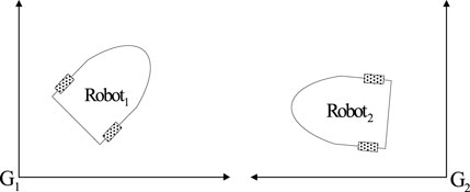
FIGURE 1. The robots and their corresponding coordinates.
Eq. 1 can be rewritten in the general non-linear state space form as follows:
where
2.2 Kinematic model of the landmarks
In this study, both landmarks are considered to be moving, with the following kinematic model:
where
By writing (3) in the general non-linear state space model, we obtain
where
2.3 Lidar measurement model
Lidar sensor output includes the distance and angle of each robot relative to the observed landmarks. Each observation by each robot of the landmarks that are present can be expressed by the following observation model:
where
3 Modified Fast-SLAM with dynamic landmarks
Robots
3.1 Particle generation
An important and initial step in the PF is particle generation. To this end, particles are generated using the known PDF of
3.2 Mapping
Each robot separately performs mapping after the particle generation process using EKF, as explained in the below subsections. After the first meeting of the robots and coordinate transformation, the maps are merged, as explained in detail in subsequent subsections.
3.2.1 EKF for mapping
• Initialization
After the particle generation process as explained in the previous subsection, when the jth landmark is visited for the first time, initialization is performed using the inverse sensor model for each particle, as follows, if it has been visited at sample instant
Where
Moreover, let predicted covariance matrix
• Prediction step
After the first visit to the jth landmark, prior estimates (predicted estimates)
where in (11)
• Data association
Data association is one of the important issues for SLAM in dynamic environments. For this purpose, in this paper, the measurement prediction is simply computed as follows:
where
For data association, the condition
• Update step
If the landmark j is observed, this step is performed in a similar way to normal Fast-SLAM, which consists of gain computation, state update, and covariance update, as follows:
where
For unobserved landmarks, the predicted values are replaced with the posterior ones; in other words,
3.3 Localization (weight computation and resampling)
In this step, the final localization process is performed through computation of the particles’ weights and a resampling process. To this end, the normalized weights are computed as follows:
where
where
It is worth mentioning that if no measurement is available, the predicted particles in (7) will be used for particle generation in the next step; additionally, they are weighted equally for the final mapping and localization,
4 Coordinate alignment and map-merging in multi-robot SLAM
As mentioned earlier, two robots,
To this end, when robots
where
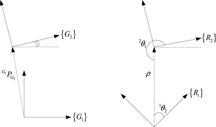
FIGURE 2. The relationships between different coordinates.
Finally, all the landmarks are presented in frame
Similarly, the map created by the first robot is presented in frame
Next,
To clarify the proposed method, the general proposed algorithm for multi-robot Fast-SLAM in a dynamic environment is presented and summarized in Algorithm 1.
Algorithm 1. The general multi-robot Fast-SLAM-based algorithm with moving landmarks.
Step 0: Initialization
at each sample time
for each robot
for each particle
Receive:
Step 1: particle generation: generate particles according to (7).
Step 2: Mapping:
Receive:
for each
• if no measurement is available but the landmark has been visited do:
1. predict according to (10), (11) and (12)
2. let
•endif
• if measurement
• do data association according to (14):
• if the landmark
1. initialization according to (8) and (9).
• elseif the landmark has been visited previously do
1. predict according to (10), (11) and (12).
2. update according (15) and (16).
•endif
•endif
Step 3: Localization:
• if measurement
1. generate particle weights according to (17) and (18).
2. perform resampling and generate equally weighted estimates, resulting in:
•endif
• if no measurement is available do
•endif
Step 4: Coordinate alignment and map merging:
• if the robot visits another robot do:
1. compute the rotation matrix,
2. transform maps in
3. transform maps in
4. fuse maps as explained in Section 4.
•endif
Return:
5 Simulation results
To evaluate the performance of the proposed multi-robot SLAM algorithm in a dynamic environment, a series of simulation studies were conducted using MATLAB m-file codes; these are reported on in this section. Two Pioneer P3-DX mobile robots, each equipped with a lidar sensor, are simulated. As mentioned earlier in the article, two moving landmarks are considered and are modeled via their kinematic models.
As mentioned earlier, robots
All of the sources of noise are considered to be zero-mean Gaussian noise; the covariance matrices of the process (kinematics) noise, for both landmarks and robots, are specified as
Once the robots meet one another, the transformation matrix between the two frames
Figures 3, 4 depict the results of the localization of robots
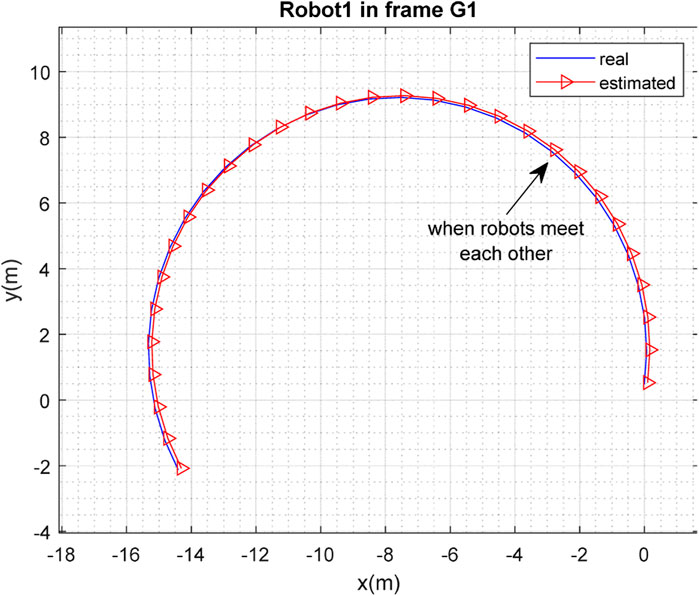
FIGURE 3. Real and estimated position of robot
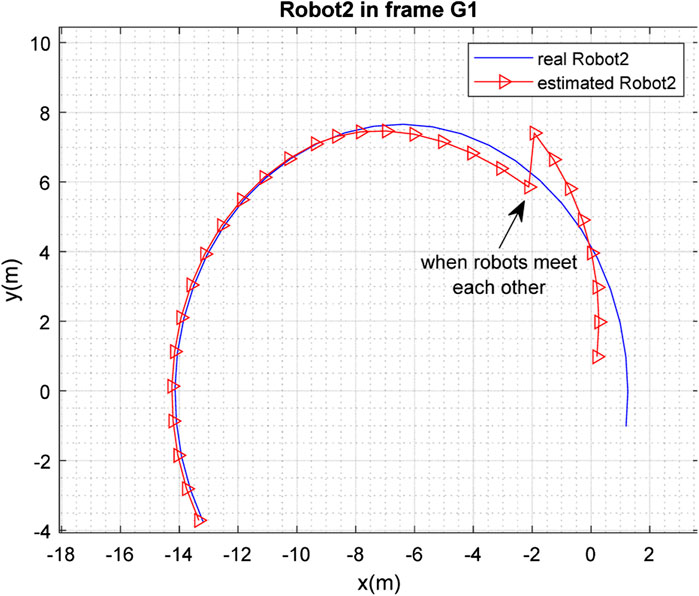
FIGURE 4. Real and estimated position of robot
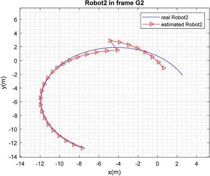
FIGURE 5. Real and estimated position of robot
The real and estimated values of
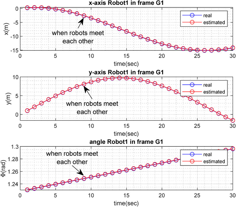
FIGURE 6. Real and estimated values of
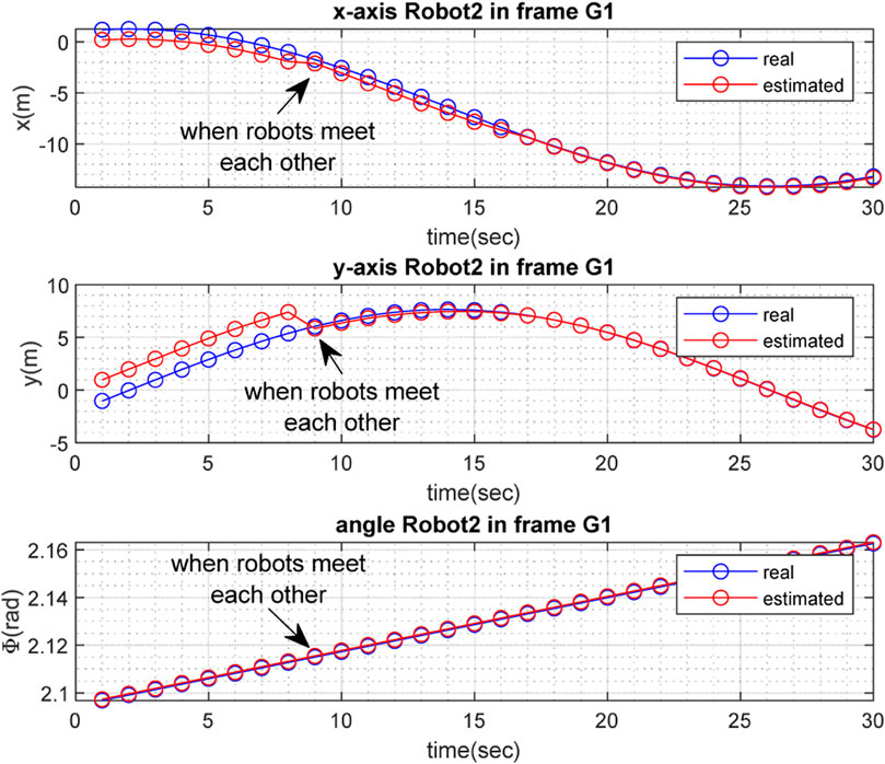
FIGURE 7. Real and estimated values of
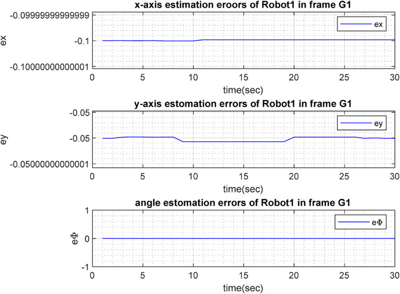
FIGURE 8. Estimation errors
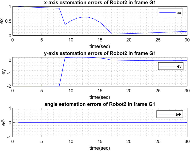
FIGURE 9. Estimation errors
The results of the mapping in 2D space are shown in Figures 10, 11 for landmarks
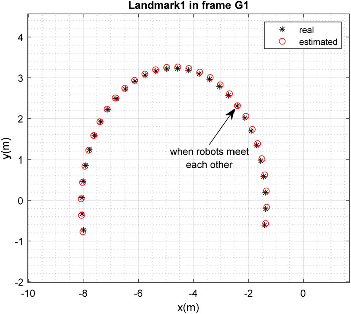
FIGURE 10. Real position of landmark
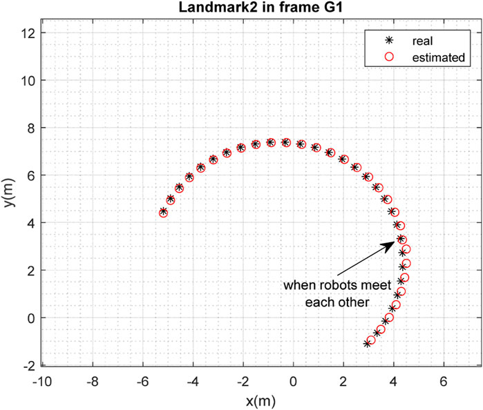
FIGURE 11. Real position of landmark
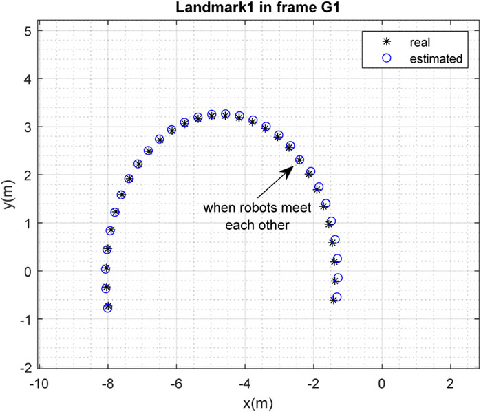
FIGURE 12. Real position of landmark

FIGURE 13. Real position of landmark
To examine the efficiency of the method for the case in which some of the conditions are altered, the initial conditions were selected as follows:
The results of localization of the robots in frame
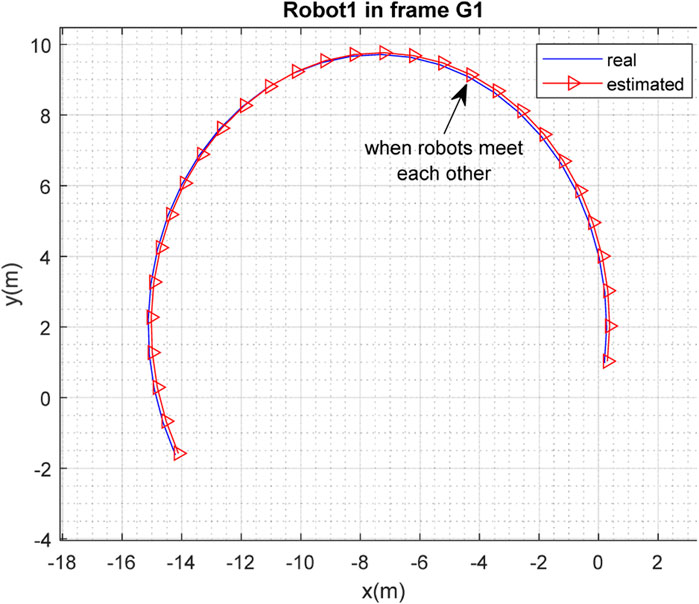
FIGURE 14. Real and estimated position of robot
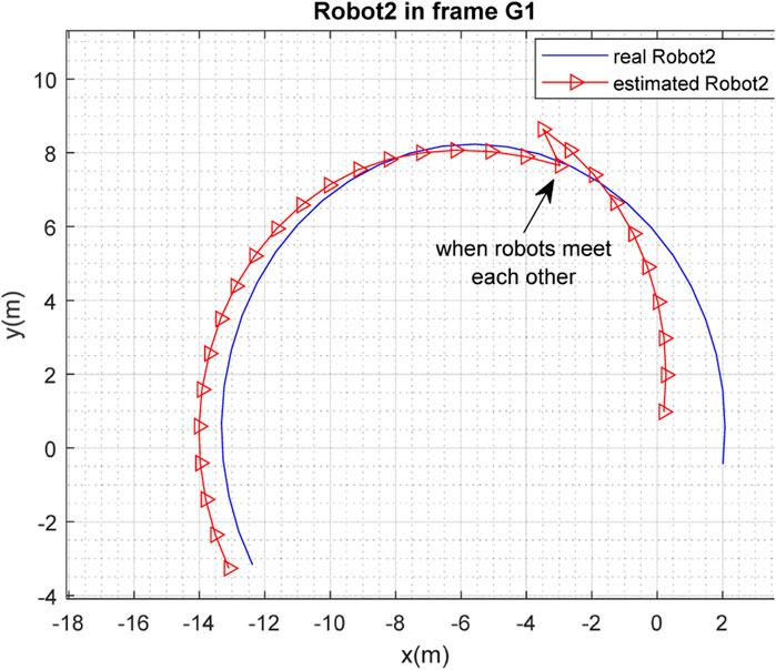
FIGURE 15. Real and estimated position of robot
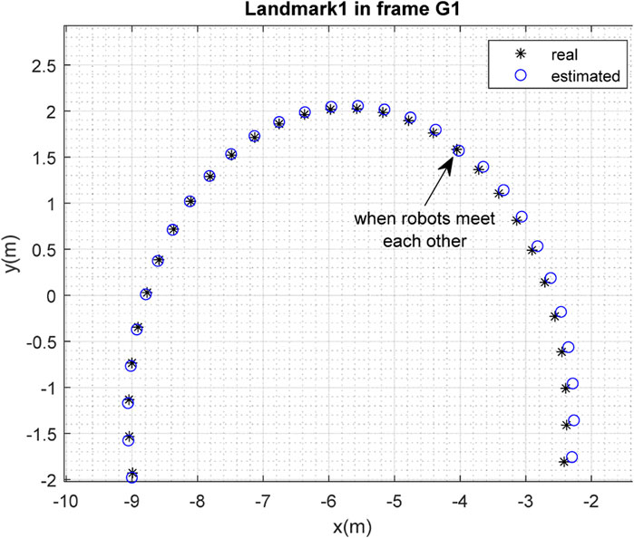
FIGURE 16. Real position of landmark
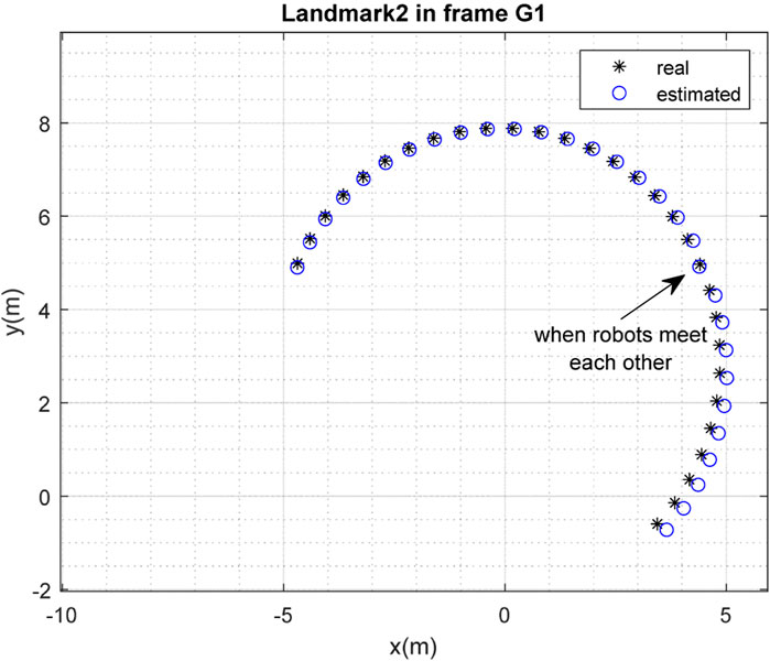
FIGURE 17. Real position of landmark
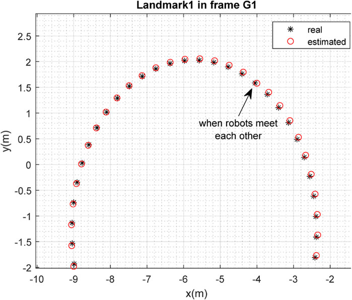
FIGURE 18. Real position of landmark
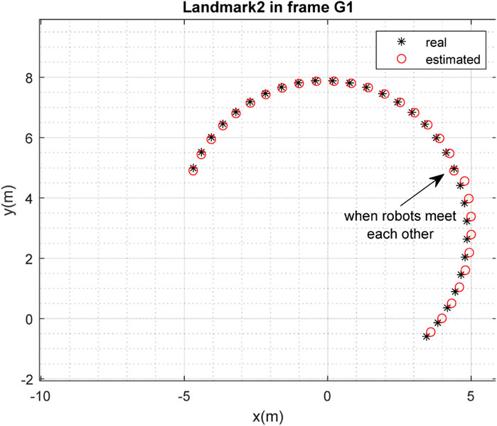
FIGURE 19. Real position of landmark
6 Conclusion
In this paper, an efficient algorithm has been presented for a multi-robot SLAM problem with unknown initial correspondence in a dynamic environment, using a modified Fast-SLAM method. In our scenario, each robot independently searches the environment, observes the moving landmarks in the environment using a lidar sensor, and implements the SLAM algorithm. In order to distinguish the moving landmarks, kinematic models are considered for the landmarks, which led to a modification of the normal Fast-SLAM method in the form of the addition of a prediction phase to the method; additionally, data association was performed according to the predicted measurements obtained from this prediction step. Although the kinematic models of the landmarks are known within each robot’s coordinate system, after the first meeting of the robots, an initialization is embedded in the algorithm to obtain the current positions of the landmarks, as they are unknown to the robots.
Since the initial correspondence of the robots is unknown (or, in other words, each robot performs the mapping from the perspective of its own coordinate frame), a map-merging procedure was embedded in the proposed algorithm to fuse the independent maps of the robots when the robots meet each other. This map-merging is only possible when the relative transformation matrix of the robots’ inertial frames is computed, which occurs when the robots meet each other. For this purpose, a geographical approach to compute this transformation matrix was embedded in the proposed algorithm.
The performance of the proposed method was evaluated through simulations in MATLAB. It can be concluded from the simulation results that although each robot was able to solve the SLAM problem with an acceptable level of performance, the accuracy of SLAM was significantly improved when the robots met each other and map-merging was performed.
Although the proposed method showed very good performance in simulations in the MATLAB environment, it will perhaps encounter some difficulties in a real environment, such as model mismatches in relation to both the landmarks and the robots due to noise, and the occurrence of drift, for example, in the inertial sensor measurements. Additionally, designing a rendezvous method for the robots to force them to visit each other can represent another issue in a real environment.
Generalization of the proposed method for the general case of a multi-robot and multi-landmark system, with more than two robots and two moving landmarks, is proposed for future work. Embedding some approach to object detection, instead of using the kinematic models of the landmarks, would also add significant value to this research.
Data availability statement
The original contributions presented in the study are included in the article/Supplementary Material, further inquiries can be directed to the corresponding authors.
Author contributions
HK: Investigation, Methodology, Software, Writing–original draft. NS-N: Conceptualization, Methodology, Project administration, Supervision, Validation, Writing–original draft. AM: Conceptualization, Funding acquisition, Project administration, Resources, Supervision, Writing–review and editing.
Funding
The author(s) declare financial support was received for the research, authorship, and/or publication of this article. This work was supported in part by the Engineering and Physical Sciences Research Council (EPSRC) under Grant EP/R02572X/1.
Conflict of interest
The authors declare that the research was conducted in the absence of any commercial or financial relationships that could be construed as a potential conflict of interest.
The author(s) declared that they were an editorial board member of Frontiers, at the time of submission. This had no impact on the peer review process and the final decision.
Publisher’s note
All claims expressed in this article are solely those of the authors and do not necessarily represent those of their affiliated organizations, or those of the publisher, the editors and the reviewers. Any product that may be evaluated in this article, or claim that may be made by its manufacturer, is not guaranteed or endorsed by the publisher.
References
Almadhoun, R., Taha, T., Seneviratne, L., and Zweiri, Y. (2019). A survey on multi-robot coverage path planning for model reconstruction and mapping. SN Appl. Sci. 1, 847–924. doi:10.1007/s42452-019-0872-y
Badalkhani, S., and Havangi, R. (2021). Effects of moving landmark’s speed on multi-robot simultaneous localization and mapping in dynamic environments. Iran. J. Electr. Electron. Eng. 17 (1), 1740. doi:10.22068/IJEEE.17.1.1740
Burrell, T., West, C., Monk, S. D., Montezeri, A., and Taylor, C. J. (2018). “Towards a cooperative robotic system for autonomous pipe cutting in nuclear decommissioning,” in UKACC 12th International Conference on Control (CONTROL), Sheffield, UK, 5-7 Sept. 2018 (IEEE), 283–288.
Chen, B., Peng, G., He, D., Zhou, C., and Hu, B. (2021). “Visual SLAM based on dynamic object detection,” in 2021 33rd Chinese Control and Decision Conference (CCDC), Germany, 22-24 May 2021 (IEEE), 5966–5971.
Debeunne, C., and Vivet, D. (2020). A review of visual-LiDAR fusion based simultaneous localization and mapping. Sensors 20 (7), 2068. doi:10.3390/s20072068
De Hoog, J., Cameron, S., and Visser, A. (2010). Selection of rendezvous points for Multi− robot exploration in dynamic environments.
Godsill, S. (2019). “Particle filtering: the first 25 years and beyond,” in ICASSP 2019-2019 IEEE International Conference on Acoustics, Speech and Signal Processing (ICASSP), China, 12-17 May 2019 (IEEE), 7760–7764.
Guan, H., Qian, C., Wu, T., Hu, X., Duan, F., and Ye, X. (2023). A dynamic scene vision SLAM method incorporating object detection and object characterization. Sustainability 15 (4), 3048. doi:10.3390/su15043048
Kretzschmar, H., Grisetti, G., and Stachniss, C. (2010). Lifelong map learning for graph-based SLAM in static environments. KI-Künstliche Intell. 24, 199–206. doi:10.1007/s13218-010-0034-2
Li, A., Wang, J., Xu, M., and Chen, Z. (2021). DP-SLAM: a visual SLAM with moving probability towards dynamic environments. Inf. Sci. 556, 128–142. doi:10.1016/j.ins.2020.12.019
Liu, H., Liu, G., Tian, G., Xin, S., and Ji, Z. (2019). “Visual SLAM based on dynamic object removal,” in IEEE International Conference on Robotics and Biomimetics (ROBIO), New York, 5-9 Dec. 2022 (IEEE), 596–601.
Lluvia, I., Lazkano, E., and Ansuategi, A. (2021). Active mapping and robot exploration: a survey. Sensors 21 (7), 2445. doi:10.3390/s21072445
Meghjani, M., and Dudek, G. (2011). “Combining multi-robot exploration and rendezvous,” in Canadian conference on computer and robot vision (USA: IEEE), 80–85.
Meghjani, M., and Dudek, G. (2012). “Multi-robot exploration and rendezvous on graphs,” in IEEE/RSJ International Conference on Intelligent Robots and Systems, USA, 23-27 Oct. 2022 (IEEE), 5270–5276.
Montazeri, A., Can, A., and Imran, I. H. (2021). Unmanned aerial systems: autonomy, cognition, and control. Unmanned aerial systems. USA: Academic Press, 47–80.
Montemerlo, M., Thrun, S., Koller, D., and Wegbreit, B. (2002). FastSLAM: a factored solution to the simultaneous localization and mapping problem. Aaai/iaai 593598. doi:10.5555/777092.777184
Pancham, A., Withey, D., and Bright, G. (2020). Amore: CNN-based moving object detection and removal towards SLAM in dynamic environments. South Afr. J. Industrial Eng. 31 (4), 46–58. doi:10.7166/31-4-2180
Romero, V., and Costa, O. (2010). “Map merging strategies for multi-robot fastSLAM: a comparative survey,” in Latin American robotics symposium and intelligent robotics meeting (America: IEEE), 61–66.
Roy, N., and Dudek, G. (2001). Collaborative robot exploration and rendezvous: algorithms, performance bounds and observations. Aut. Robots 11, 117–136. doi:10.1023/a:1011219024159
Sadeghzadeh-Nokhodberiz, N., Can, A., Stolkin, R., and Montazeri, A. (2021). Dynamics-based modified fast simultaneous localization and mapping for unmanned aerial vehicles with joint inertial sensor bias and drift estimation. IEEE Access 9, 120247–120260. doi:10.1109/access.2021.3106864
Saeedi, S., Trentini, M., Seto, M., and Li, H. (2016). Multiple-robot simultaneous localization and mapping: a review. J. Field Robotics 33 (1), 3–46. doi:10.1002/rob.21620
Saputra, M. R. U., Markham, A., and Trigoni, N. (2018). Visual SLAM and structure from motion in dynamic environments: a survey. ACM Comput. Surv. (CSUR) 51 (2), 1–36. doi:10.1145/3177853
Stachniss, C., Leonard, J. J., and Thrun, S. (2016). Simultaneous localization and mapping. Germany: Springer Handbook of Robotics, 1153–1176.
Theodorou, C., Velisavljevic, V., and Dyo, V. (2022). Visual SLAM for dynamic environments based on object detection and optical flow for dynamic object removal. Sensors 22 (19), 7553. doi:10.3390/s22197553
Vidal, F. S., Barcelos, A. d. O. P., and Rosa, P. F. F. (2015). “SLAM solution based on particle filter with outliers filtering in dynamic environments,” in IEEE 24th International Symposium on Industrial Electronics (ISIE, USA, 3-5 June 2015 (IEEE), 644–649.
Keywords: SLAM, multi-robot SLAM, Fast-SLAM, dynamic environments, moving landmarks, map merging
Citation: Malakouti-Khah H, Sadeghzadeh-Nokhodberiz N and Montazeri A (2024) Simultaneous localization and mapping in a multi-robot system in a dynamic environment with unknown initial correspondence. Front. Robot. AI 10:1291672. doi: 10.3389/frobt.2023.1291672
Received: 09 September 2023; Accepted: 11 December 2023;
Published: 11 January 2024.
Edited by:
Alessandro Ridolfi, University of Florence, ItalyReviewed by:
Alessandro Bucci, University of Florence, ItalyRoohollah Barzamini, Islamic Azad University Central Tehran Branch, Iran
Maral Partovibakhsh, Islamic Azad University System, Iran
Copyright © 2024 Malakouti-Khah, Sadeghzadeh-Nokhodberiz and Montazeri. This is an open-access article distributed under the terms of the Creative Commons Attribution License (CC BY). The use, distribution or reproduction in other forums is permitted, provided the original author(s) and the copyright owner(s) are credited and that the original publication in this journal is cited, in accordance with accepted academic practice. No use, distribution or reproduction is permitted which does not comply with these terms.
*Correspondence: Nargess Sadeghzadeh-Nokhodberiz, c2FkZWdoemFkZWhAcXV0LmFjLmly; Allahyar Montazeri, YS5tb250YXplcmlAbGFuY2FzdGVyLmFjLnVr