Identification of harmonic sources in smart grid using systematic feature extraction from non-active powers
- 1Department of Electrical and Electronics Engineering, Dadi Institute of Engineering and Technology, Anakapalle, India
- 2School of Electrical Engineering, Kalinga institute of Industrial Technology (KIIT) University, Bhubaneswar, India
- 3Department of Electrical Engineering, Birsa Institute of Technology (BIT) Sindri, Dhanbad, India
- 4Fukushima Renewable Energy Institute, Advanced Industrial Science and Technology (AIST), Koriyama, Japan
The paper introduces a novel method for identifying the location of harmonic-generating sources in smartgrids. The method utilizes a Dual-Tree Complex Wavelet Transform (DTCWT) of voltage and current signals measured at a specific point in the network. By applying DTCWT Transform, the signals are decomposed, and three non-active power quantities are extracted to represent the harmonic components within the system exclusively. These chosen non-active power quantities serve as indicators of the presence of harmonics in the system. Through analysis and comparison of these quantities, the method enables determining the precise location of the dominant harmonic generating source. This information is valuable for effectively addressing and mitigating harmonic issues in the network. Leveraging DTCWT and focusing on non-active power quantities provides a valuable tool for power system engineers and operators to diagnose and mitigate harmonic issues, ultimately improving power quality and system performance. This study presents a new feature extraction method to compute Non-active power quantities based on DTCWT due to its shift-invariant property.
1 Introduction
Power quality disturbances have become a significant concern for the power industry due to their adverse impact on the power system's reliability and stability. The detection and classification of power quality disturbances (PQDs) is a critical issue in the power system. Researchers have proposed different techniques to improve the accuracy and efficiency of PQD detection and classification. By accurately identifying the source, it becomes easier to implement targeted solutions and prevent future disruptions. Moreover, it aids in improving the overall performance of the power system and reducing downtime. Harmonics can degrade power quality, leading to issues such as voltage distortion and increased losses in the power distribution system. Identifying harmonic sources helps utilities improve power quality, ensuring a stable and reliable electricity supply for consumers. Harmonics can negatively impact the lifespan and performance of electrical equipment. Identifying sources allows for the implementation of protective measures and targeted maintenance strategies to ensure the reliability and longevity of equipment in the smart grid. Harmonics result in energy losses and decreased efficiency in power systems. By identifying and mitigating harmonic sources, utilities can improve energy efficiency, reducing unnecessary energy consumption and operational costs. Many regions have regulations and standards in place to limit harmonic distortions in power systems. Identifying harmonic sources is crucial for compliance with these regulations, avoiding penalties, and maintaining a grid that meets established standards. In a smart grid, where advanced communication and control technologies are integrated, identifying harmonic sources is essential for optimizing grid performance. It enables utilities to make informed decisions, implement efficient control strategies, and adapt to changing conditions in real-time. The ability to identify harmonic sources allows utilities to adopt a proactive approach to maintenance. Predictive maintenance based on systematic feature extraction helps prevent equipment failures, reduce downtime, and minimize overall maintenance costs. With the increasing integration of renewable energy sources like solar and wind power, harmonic issues can arise due to the variable nature of these sources. Identifying and mitigating harmonics is essential for the smooth integration of renewable energy into the grid. So, harmonics should be addressed as soon as possible to increase the reliability of the smart grid. Discrete Wavelet Transform (DWT) is a powerful tool for detecting and classifying power quality disturbances in a power system. DWT has been used in many research works to extract the features of various power quality disturbances such as harmonics, transients, and inter-harmonics. The extracted features are then fed into different classification algorithms to identify and classify the type of power quality disturbance. However, there exist some research gaps while using DWT for this purpose. One such gap is that the DWT-based approach may not be very effective in capturing the high-frequency components of PQ disturbances. To overcome this research gap, researchers have proposed the use of Dual-Tree Complex Wavelets Transform (DT-CWT). DT-CWT is known for its ability to provide better time and frequency resolution than DWT, making it a suitable alternative for detecting and classifying PQ disturbances.
Dual-Tree Complex Wavelet Transform (DT-CWT) is considered better than Discrete Wavelet Transform (DWT) for detecting and classifying Power Quality (PQ) disturbances in a power system for several reasons. DT-CWT provides better time and frequency resolution, making it more effective in capturing high-frequency components of PQ disturbances. It can handle non-stationary signals more effectively, has a higher degree of shift-invariance, and a larger number of wavelet coefficients, providing more information about the signal. DT-CWT can also handle complex signals with multiple modes and provide directional information about the signal, making it useful to identify and classify power quality disturbances in multi-phase systems. Additionally, it provides a more interpretable representation of the signal than DWT and can be used with other signal processing techniques to improve accuracy. Finally, DT-CWT is a versatile signal-processing technique with numerous applications beyond PQ disturbance detection and classification.
Granados-Lieberman et al. (2011) provided a comprehensive review of different methods and techniques for analyzing the power quality events and their classification in the power systems. The authors discussed the various signal processing techniques used for power quality analysis, including Fourier Transform, Wavelet Transform, and Stockwell Transform. They also reviewed different classifiers, such as Artificial Neural Networks, Support Vector Machines, and Fuzzy Logic Systems, for disturbance classification. Reddy et al. (2014) proposed a versatile real-time power quality analyzer that uses the Stockwell Transform for signal analysis. In real time, the proposed system can detect and classify various power quality disturbances, including harmonics, voltage sags, and swells. Masoum et al. (2010) proposed a method for detecting and classifying power quality disturbances using the Discrete Wavelet Transform and Wavelet Networks. The proposed method showed high accuracy in detecting and classifying disturbances. Khokhar et al. (2016) proposed a mechanized pattern recognition system for various multi-power quality events. The authors used the Artificial Neural Network classifier for disturbance classification and achieved an accuracy of 98.5%. Parvez et al. (2019) proposed an online power quality disturbance detection system using the Support Vector Machine classifier. With high accuracy, the proposed system can detect various disturbances, including voltage sag, swell, and interruption. Yan et al. (2019) proposed a method for denoising and detecting transient power quality disturbances using an improved Iterative Adaptive Kernel Regression algorithm. The proposed method showed high accuracy in detecting and classifying different types of disturbances. Lin et al. (2019) proposed a method for feature selection and pattern recognition of power quality disturbances based on image enhancement techniques. The proposed method used the Discrete Wavelet Transform for feature extraction and achieved high accuracy in disturbance classification. Gong and Ruan (2020) proposed a convolutional network structure for power quality disturbance identification and classification in microgrids. The proposed method accurately identified and classified various power quality disturbances, including voltage sag, swell, and harmonics. Xu et al. (2020) proposed a method for detecting and classifying power quality disturbances in distribution networks using Variational Mode Decomposition and DFA. The proposed method showed high accuracy in detecting and classifying disturbances, even in noisy environments. Chawda et al. (2020) comprehensively reviewed different techniques and methodologies for detecting and classifying power quality disturbances in utility grids with renewable energy penetration. The authors discussed various signal processing techniques and classifiers used for disturbance classification, including Artificial Neural Networks, Support Vector Machines, and Decision Trees. Meena et al. (2022) proposed a power quality disturbance classification method using DWT-based feature extraction. The proposed method achieved high accuracy in disturbance classification. Zhong et al. (2019) proposed a PQ Events identification system based on S-Transform in combination with a Decision Tree classifier. The proposed method accurately identified and classified various power quality disturbances, including harmonics and voltage sags. Özmen and Biricik (2019) proposed a PQD detection technique based on the dual-tree complex wavelet transform (DTCWT). The proposed method improves the sensitivity and selectivity of PQD detection in the presence of harmonics. The experimental results show that the proposed method outperforms the conventional discrete wavelet transform (DWT) technique in terms of accuracy. Deng et al. (2021) proposed a PQD detection and classification technique based on the variational mode decomposition (VMD) and convolutional neural networks (CNN). The VMD decomposes the PQD signal into different modes, and the CNN is used to classify the modes into different PQDs. The proposed method achieves a high accuracy rate for PQD detection and classification. Ra et al. (2018) proposed a PQD detection technique based on the DTCWT. The proposed method improves the sensitivity and selectivity of PQD detection in the presence of noise. The experimental results show that the proposed method outperforms the conventional DWT technique in terms of accuracy. Mahela et al. (2020) proposed a PQD recognition technique based on the S-transform and ruled decision tree (RDT). The S-transform decomposes the PQD signal into different frequency components, and the RDT is used to classify the frequency components into different PQDs. The proposed method achieves a high accuracy rate for PQD recognition. Liu et al. (2021) proposed a PQD classification technique based on time-dependent spectral features and a three-step classification approach. The proposed method employs a time-frequency analysis to extract time-dependent spectral features, which are then used to classify PQDs into different categories. The proposed method achieves a high accuracy rate for PQD classification. Shaik et al. (2022) proposed a PQD identification technique based on the DTCWT and support vector machine (SVM). The proposed method identifies single and multiple PQDs using the DTCWT to extract the features and the SVM to classify the PQDs. The experimental results show that the proposed method achieves a high accuracy rate for PQD identification. Finally, Khoa and Dai (2020) proposed a PQD detection and classification technique based on an improved combination of the S-transform with a decision tree classifier. The proposed method employs the Stockwell transform to extract time-frequency features and the decision tree method to classify the PQDs. The experimental results show that the proposed method achieves a high PQD detection and classification accuracy rate. This research introduces a novel approach for fault identification in power networks by making use of deep learning approach It is possible to estimate the type, classification and the distance to the site of the defect (Roy et al., 2023). Latif (2020) suggest using a price based demand response approach to incorporate more renewables into the grid, in order to solve the issue outlined before. Firstly, the parameters of the control systems being presented are optimized using the salp swarm optimization (SSO) approach. Mahafzah et al. (2022) introduce a novel protection mechanism that utilizes artificial intelligence to identify faults under various operating settings. The suggested approach has many benefits over existing methods, such as its fast protective functioning and offering a fault recovery method. Ye et al. (2024) presents novel and tailored approaches to handle the issue of time synchronization loss in D-PMUs, H-PMUs, and WMUs, taking into account the specific constraints associated with each of these cases. We are primarily dedicated to resolving the issue of identifying the location of events, both steady-state and transient, across many categories. Yin et al. (2024) proposed a method to identify multiple harmonic sources using a collaborative approach including cloud, edge, and end devices. Firstly, based on the study of the functional requirements harmonic sources assessment at many voltage levels, a new framework of cloud-edge-end collaboration is provided. The suggested technique is the cloud-edge-end collaborative harmonic sources assessment method. It operates distinct service strategies dependent on voltage levels and grid operation. This is achieved via the multi-level interaction of edge computing. The proposed GAC (Xu et al., 2024) seeks to identify the primary source of harmonics at the point of common coupling (PCC) from both the utility and consumer perspectives. The new approach requires simply the root mean square (RMS) values of the PCC voltage, current, and phase angle difference, in contrast to the standard method. Hence, the need for synchronized phasor data of voltage and current is eliminated. Simultaneously, a criterion for identifying the primary harmonic source is constructed by comparing the equivalent admittance ratio on both sides of the point of common coupling (PCC). By applying sophisticated control methodologies, the interface inverters perform several auxiliary services which include suppression of harmonics, power factor as well as voltage correction. This research introduces a new approach called Adaptive Neuro Fuzzy Inference System based Hybrid Aquila Arithmetic Optimization (ANFIS-HA2O) to improve power quality and reduce harmonics in distributed generation (DG) systems (Zahariah, 2024). Chauhan et al. (2022) presents a model for reducing emissions by implementing a carbon capture system that includes a small-scale carbon capture unit (CCU) integrated with a fossil fuel-based unit. Carbon emissions are subject to a fractional penalty based on the efficiency of the CCU system. Safiullah et al. (2022) employs a control strategy to achieve stable power supply in the presence of electric vehicles (EVs) and renewable energy sources. An AI-based disturbance rejection controller is employed.
This article shows that Dual-Tree Complex Wavelet Transform (DTCWT) is superior to the traditional Discrete Wavelet Transform (DWT) for detecting harmonic sources in power systems. This is mainly due to the fact that DTCWT provides a better time-frequency resolution and can capture the subtle changes in the signal that DWT fails to identify. The main attributes of the wavelet transform cause major dependencies in the wavelet coefficients of natural images: It has been found that (1) large/small wavelet coefficients tend to propagate across scales (Sendur and Selesnick, 2002), and (2) neighboring large/small wavelet coefficients tend to be large/small as well. For denoising the signals, Borran and Nowak (2001) proposes a wavelet-based hidden Markov tree (HMT) model that takes use of sign and magnitude correlations on adjacent scales. This paper employs the bivariate Cauchy PDF to represent the scaling behavior of the coefficients in the dual-tree complex wavelet transform (DTCWT) (Achim and Kuruoglu, 2005). Compared to the conventional discrete wavelet transform (Kingsbury, 2001), DTCWT excels due to its near-perfect shift invariance, excellent directional selectivity in two dimensions, and flawless reconstruction. The studies reviewed in this literature review have demonstrated that DTCWT-based methods can accurately detect and classify various power quality disturbances, including complex harmonic sources, using machine learning techniques such as decision trees, SVM, and convolutional neural networks. Moreover, the studies have shown that the DTCWT-based methods can perform well even under noisy conditions and achieve high detection accuracy with relatively low computational complexity. Therefore, DTCWT-based methods can greatly improve the performance of power systems and enhance the reliability of power quality monitoring systems. Systematic feature extraction involves the use of advanced data analytics techniques to process large sets of data efficiently. This innovation allows for the identification of patterns and trends related to non-active powers, providing insights into harmonic sources in a more sophisticated manner than traditional methods. Integration of machine learning and artificial intelligence algorithms enables the smart grid system to learn and adapt over time. These algorithms can automatically identify and classify harmonic sources based on historical and real-time data, improving the accuracy of source identification. The innovation involves implementing real-time monitoring capabilities, allowing for immediate detection and response to harmonic issues as they arise. This dynamic response contributes to the stability of the smart grid and minimizes the impact of harmonic distortions on power quality. Utilization of smart sensors with advanced measurement capabilities enhances the accuracy of data collection. These sensors can provide detailed information about non-active powers, facilitating more precise feature extraction and harmonic source identification. Innovations in control strategies enable the smart grid to adapt dynamically to changing conditions. By understanding the characteristics of harmonic sources through systematic feature extraction, the system can adjust control parameters to mitigate harmonic issues effectively. The application of predictive maintenance techniques based on systematic feature extraction allows for the anticipation of potential harmonic-related equipment failures. This innovation helps utilities implement timely maintenance actions, reducing downtime and improving overall system reliability. Innovative visualization tools and reporting mechanisms provide clear insights into harmonic sources. This enables utility operators and engineers to make informed decisions for harmonic mitigation and overall grid optimization.
1.1 Main novelty
In this paper, the author presents a new method for identifying the dominant harmonic source smart grid. The relative phase angle between the sources influences the conventional approach of using active power direction for locating harmonic sources. Additionally, the metering point and source/customer impedance can impact the accuracy of the active power direction method.
To overcome these limitations, the author focuses on nonactive power components that represent the harmonic components in the power system network. Three different nonactive powers are utilized: detail reactive power, Czarneck's reactive power, and a newly introduced nonactive power, N/. These powers are formulated in the wavelet domain.
The proposed method relies on comparing these nonactive power quantities to detect the harmonic sources in the power system network. By analyzing the characteristics of these powers, the dominant harmonic source can be identified more effectively.
Previous studies have also proposed various techniques for harmonic source detection and power quality monitoring. These include a current decomposition technique for measuring power resolutions defined by different authors, a single-point strategy for detecting harmonic sources in polluted power systems, and an innovative technique for identifying disturbing loads in distorted power systems. These methods often involve comparing nonactive power quantities measured at the same metering section.
The effectiveness of the proposed method is evaluated by incorporating simple decision-making rules and considering the influence of measurement transducers. The proposed method offers a promising approach for identifying and locating dominant harmonic sources in power system networks by utilizing the nonactive power quantities and formulating them in the wavelet domain.
1.2 Advantages
1. Systematic feature extraction involves analyzing large datasets to identify patterns and trends related to harmonic sources. This data-driven approach enables utilities to make informed decisions and optimize their strategies for harmonic mitigation.
2. As the share of renewable energy sources like solar and wind power increases, so does the complexity of the power grid. Harmonic issues can arise due to the variable nature of these energy sources. Systematic feature extraction helps in understanding and addressing harmonic challenges associated with the integration of renewable energy into the grid.
3. By understanding the characteristics of harmonic sources, utilities can implement better monitoring and control strategies. This allows for real-time adjustments and responses to changing conditions, maintaining optimal system performance.
4. Systematic feature extraction from non-active powers can provide insights into the behavior of harmonic sources over time. This information can be used for predictive and preventive maintenance, reducing downtime and minimizing the likelihood of equipment failures.
5. Harmonics can result in energy losses and reduced efficiency in power systems. Identifying and mitigating harmonic sources can lead to improved energy efficiency, reducing unnecessary energy consumption and associated costs.
2 The evaluation of the proposed approach
The proposed approach of detecting the harmonic generating source is based on comparing three nonactive power components defined in the context of non-sinusoidal electrical systems. Several power components have been defined during the past years to analyze, understand, and measure power quantities in power systems in the presence of nonlinear components (Balci and Hocaoglu, 2010). Especially the reactive powers can be used as indicators for detecting the location of harmonic sources. Some of these reactive power quantities are Budeanu (QB), Fryze (QF), Shepherd and Zkikhani (Sx), Sharon (Sq), Kuster and Moore (Qkus), and Czarnecki (Qcz). For the detection of dominating harmonic sources, the authors have considered the following nonactive power quantities:
(a) Detail reactive power, Qdet
(b) Czarneck's reactive power, Qcz
(c) Another nonactive power, N/, derived from the nonactive power N defined in IEEE Std. 1459-2000 (Yin et al., 2024).
Some definitions for the power components in non-sinusoidal conditions can be found in IEEE Standard 1459-2000. The standard's newly-introduced definitions are grounded on the Fourier transform's frequency domain (FT).
2.1 Fast Fourier transform based power component definition
This section redefines power components definitions in IEEE Standard 1459-2000 (Morsi and El-Hawary, 2007) for single-phase systems under non-sinusoidal situations. Consider the following sinusoidal and non-sinusoidal voltage and current waveforms in (Equations 1–3):
Power system frequency components (=2f=100 rad/s) are represented by v1, i1; vH, iH represent overall harmonic voltage and current components; fundamental voltage and current phase angle are represented by 1; and individual harmonic voltage and current phase angle are represented by αh, βh.
T is the time frame in question. Nonsinusoidal voltage and current are defined in terms of their root-mean-square (RMS) values in Equations (4) and (5).
The fundamental active power P1 is defined as in Equation (6)
where θ1 = β1−α1
PH is the total harmonic active power given by Equation (7)
The total active power P is defined as in Equation (8)
Total harmonic reactive power is defined as1 in Equation (9)
Czarneck's reactive power Qcz is defined as in Equations (10) and (11) (see text footnote 1)
where
The distortion power, is expressed in Equation (12)
where SH is the harmonic apparent power is as in Equation (13)
The current distortion power DI, and voltage distortion power Dv are defined as in Equation (14)
The fundamental apparent power is defined as in Equation (15)
Total apparent power is defined as in Equation Equation (16)
The total non fundamental apparent power in Equation Equation (17)
The Nonactive power N is defined in IEEE Std. 1459-2000 (Cataliotti et al., 2011) as in Equation (18)
From Equations (7), (19) can be written as
Subtracting the fundamental reactive power Q1 from the non-active power N, a new nonactive power containing the harmonic quantities may be defined as in Equation (20)
The harmonic pollution is defined as in Equation (21)
2.2 The definition of a power component using a dual-tree complex wavelet transform
Signals for voltage [v(t)] and current [i(t)] are notated respectively (t). Time Period consideration is a crucial aim of the dual-tree complex wavelet transform-based signal decomposition strategy. As the number of signal samples to be decomposed grows, so does the number of decomposition levels. When performing calculations, the values of the complex coefficients are used as though they were whole numbers. This will drastically improve the calculation's performance while simultaneously lowering output error to zero. The coefficients of the voltage signal, both exact and approximate, are considered. The current coefficients for approximation and detail are also taken into account.
In Vatansever (2010), discusses his method for determining the rms value of power using the dual-tree complex wavelet transform. For the wavelet transform of a signal to be consistent with the dual-tree complex wavelet transform, Fahri Vatansever modified the exact and approximation coefficients. The following is the formula developed by Fahri Vatansever for the one-sided decomposition signal: The root-mean-square (RMS) values of a voltage or current waveform are defined as in (Equations 22–28)
The detail distortion power is as in Equation (29)
where Sdet is the detail apparent power (Zahariah, 2024) and expressed as in Equation (30)
The current distortion power DI and voltage distortion power Dv are defined as in Equation (31)
The approximation apparent power is defined as
Total apparent power is defined as in Equation (32)
The total non-fundamental apparent power is as in Equation (33)
The Nonactive power N as defined in IEEE Std. 1459-2000 (see text footnote 1) is as in Equation (34)
The proposed nonactive power N/is given as in Equation (35)
The detail pollution is as in Equation (36)
In case of nonlinear load, the amount of current distortion is low (Locci et al., 2007). Hence from Equations (28), (37), and (38), it can be concluded that, when value of Qcz is closer to Qdet, i.e., |Qcz−Qdet| < , which means only non-linear load is present in the network.
In presence of nonlinear load, the amount of current distortion will be much higher than the previous case (Sendur and Selesnick, 2002). Hence the value of Qcz will be closer to N/i.e., |Qcz−Qdet|>. This indicates that the EV load is present along with the non-linear residential load.
In presence of only EV load Qcz lies in between to Qdet and N/, then we can propose |Qcz−Qdet|= .
Feature Extraction is a method for creating new features from existing ones in a dataset in order to reduce the size of the original dataset (and then discarding the original features). Statistical feature selection and feature elimination (DTCWT) has been proved to be an efficient method for identifying suggested events by reducing the number of signal features. It also details how to select a level of decomposition that will both hasten the procedure and improve its accuracy.
3 Verification of the proposed method
3.1 Optimal placement of smart meters using Slime Mold Algorithm (SMA)
To identify the problem in the distribution line, smart meters will need to be installed, and the fault will need to be located. By installing fewer smart meters, it will be possible to cut down on the cost of the installation. To lessen the number of smart meters and zero in on the spot that would be most suitable for one of these devices, an essential optimization strategy has to be implemented. In this article, an optimization strategy that is based on the Slime Mold Algorithm (SMA) optimizer is used to determine the optimal placement of the smart meter. It is commonly acknowledged that the objective function of the Optimal Placement Problem (OPP) should be as in Equation (37)
Where C is a connectivity matrix, and n is the number of buses. The Matrix C is represented in the form of
Whereas B is a column matrix and it is represented as
3.1.1 Slime Mold Algorithm (SMA)
Premkumar et al. proposed the SMA which has been inspired by the behavioral aspect of slime mold (Premkumar et al., 2021). In nature, the slime mold detects the food and thereafter encircles it and eventually digests it by releasing enzymes. The properties of slime mold may be mathematically expressed into three steps: seeking food, encapsulating food, and oscillating, which can be represented as follows:
3.1.1.1. Approach food
The slime mold tracks the food based upon the smell dissipated in the air which can be represented as in Equation (38):
Here Equation (2), Z represents the position of the slime mold, Zb denotes the latest location with the most intensified smell (food location), ZA and ZB are randomly selected candidate from the slime mold, r is a random value between [0,1],k denotes the iterations, H signifies the slime mold adaptive weight, vb is the randomly generated value in the range [-a, a],vc represented random value in the range [-b, b] where b resembles a value that decreases linearly from 1 to 0 based upon the iteration (b = 1−k/Itermax). The probability index p of Equation (39) can be represented as in Equation (3):
Here Equation (3), J(k) represents the fitness value corresponding to Z and EG resembles the best candidate solution achieved so far. The parameter a can be represented as in Equation (40):
The adaptive weight H of the slime mold can be represented as in Equations (41), (42):
Here Equations (5) and (6), bG resembles the best fitness solution achieved in the current position and the worst fitness resembles wG the latest position. SmellIndex represents the sorted values of the fitness maintained sequentially.
3.1.1.2 Wrap food
The slime mold modifies the search procedure based on the concentration of food as it approaches the feeding process. Situation when the food concentration is low, the area's weight decreases; when the food concentration is high, the area's weight increases. However, to enhance the SMA's exploration ability, the Equation (43) may be used to update the position of the slime mold.
Here in Equation (7), the lower and the upper bounds of the decision variables are represented by lb and ub, Rand resembles the randomly generated value [0,1], and x is set to 0.03 as the best value based upon trial runs.
3.1.1.3 Oscillations
The oscillation phase imitates the propagation wave created. A biological oscillator that generates a propagation wave modifies the cytoplasmic flow in veins. This created wave is utilized to imitate varying venous widths and is mostly utilized by slime mold to locate a food source with a higher concentration. In the presence of a higher concentration of food, slime mold can access a spot more promptly; yet, it advances more slowly in the presence of lower food concentrations. Thus, the effectiveness of picking the appropriate food source is increased. The selective behavior
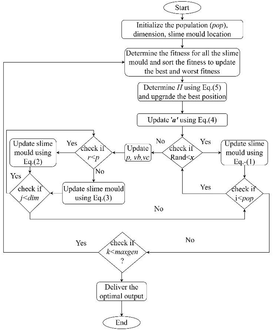
is imitated by the synergistic interaction between vb and vc. Some biological matter is separated by slime mold for the aim of exploring other regions. This behavior aids in the exploration of a higher-quality food source, even if an acceptable food source has already been discovered. This scenario also inhibits the slime mold from investigating a single source. In addition, the oscillation mechanism vc simulates the decision of whether to approach a food source or search for an alternative. Without becoming trapped in a local optimum, the likelihood of locating a foodstuff of greater quality increases although there may be a few conditions, such as a dry atmosphere and bright light, which prevent the spread of slime mold. The flow chart for optimal placement of smart meters through the Slime Mold Algorithm (SMA) is shown in Figure 1 to solve the optimum placement issue, the IEEE 33 radial distribution bus is being considered. It has been determined that the optimal solution for the objective function has been achieved, and cases of these optimal solutions can be found in Table 1.
4 System modeling of Korean smart distribution management system (KSDMS)
The system architecture of the KSDMS servers is shown in Figure 2, along with the connections made via middleware between the various parts. Data Communication Processor (DCP) is used to connect to the server and exchange data with field devices (Song et al., 2013). HCIs (human computer interfaces), engineering stations for DB and schematic editing, and middleware that connects the application server and DBMS server to each component are other system components. A single distribution branch center, which normally has 200 distribution feeders, is covered by the KSDMS. A topological characteristic matrix's size (such as the Y, H, or Jacobean matrices) may exceed the size of the whole transmission system. As a result, a reduction technique is required to reduce the size of the network. Hence in the research paper also same branch reduction technique has been applied based on Song et al. (2013) and this is shown in Figure 3.
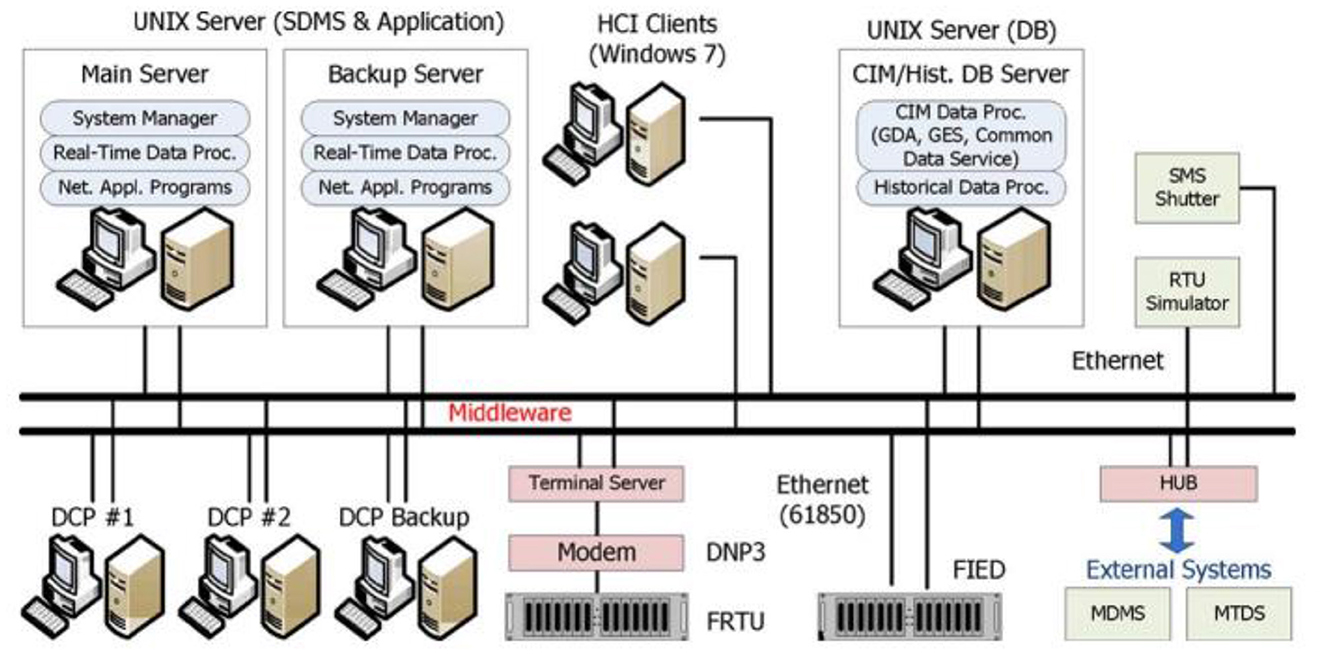
Figure 2. Architecture of server system (Achim and Kuruoglu, 2005).
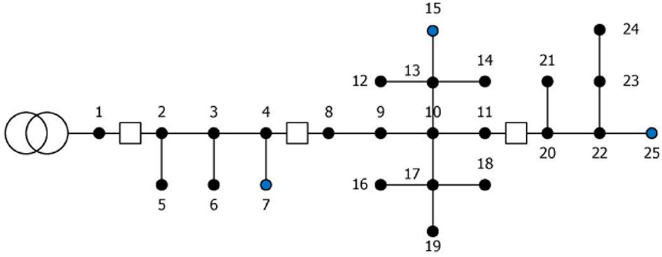
Figure 3. Architecture of KSDMS (Achim and Kuruoglu, 2005).
It is demonstrated that the proposed method is still effective at locating the origin of harmonics with respect to a measurement site even when these conditions apply. Here, a current source with a third, fifth, 7th and 11th order harmonic component is used to simulate a nonlinear load. When all the loads are linear, the approximation power flow and detail power flows up to fifth level of decomposition are shown in Figure 5 considering 6 kHz sampling frequency. Figure 6 shows the detail power flow in the lines for level 1, 4 and 5 when the nonlinear load connected at bus 4 is supplying third harmonic current and then fifth harmonic current. The corresponding powers at different buses are shown in Figure 8. From the bus data of Figure 8 it is observed that bus 4 is delivering harmonic power and all other buses are absorbing harmonic power. When bus 4 is delivering 3rd harmonic power the detail power at fifth decomposition level i.e., Pdet5 increases. Similarly, when nonlinear load connected at bus 4 is delivering fifth harmonic power then the detail powers at fourth decomposition level increases and bus 4 is polluting the system by injecting harmonics. Figures 11–13 shows the voltage, current and harmonic active power flow respectively. Figure 14 shows the captured harmonics by using DTCWT.
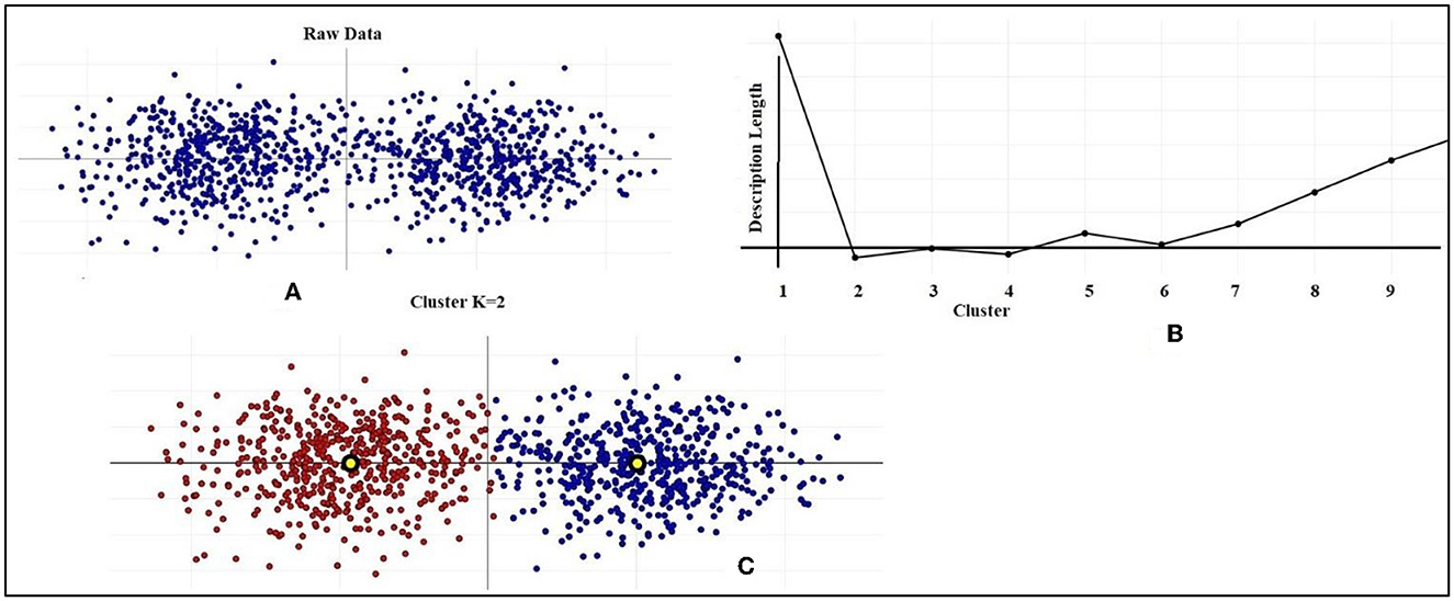
Figure 8. Data clustering and MDL. (A) Raw Data distribution. (B) Cluster vs. Length. (C) Cluster where K = 2.
5 Reduction of noise
Source separation with non-negative matrices (SSNMF) is an effective technique, as demonstrated in Ulinuha et al. (2011). Visually, the SSNMF technique is depicted as a sweep sequence of amplitude spectra. Thanks to the SSNMF decomposition, the frequency-following response (FFR) is more clearly visible, and background noise has been reduced or eliminated in all recordings. A model is developed by analyzing the trends in FFR improvement and noise reduction with increasing numbers of sweeps, and fitting this data with an exponential curve. It has been suggested that the SSNMF algorithm be applied to the FFR signal in order to assess the ability of neuroplasticity devices and pitch processing and in the electrical signal in the face of perturbations (Vatansever, 2010). In this notation, k represents the kth of n bases, it represents data in the initial dimension of a matrix (a smooth vector of frequency time), and j represents elements along the second dimension of a matrix (a sequence of amplitude spectrograms) and it is shown in Figure 4.
Due to the fact that matrices V and H were not negative, NMF applications demonstrated that they were able to learn the part-based representation required to reconstruct the data. This constraint, which assumed that the given initial data was a linear sum of various sources, reflected the additive nature of electrical signals.
H and W are the matrices which are initialized with random values before being subjected to the standard NMF multiplicative updating procedure. The effectiveness of the SSNMF algorithm is demonstrated by a sweep series of amplitude spectrograms derived from recordings of adults and newborns (Ulinuha et al., 2011). As such, this tactic is incorporated into the proposed solution.
An approach for machine learning that takes as input a non-negative matrix A and utilizes it to learn and factorize two smaller matrices, S (the spectral basis) and T (the information coding) as shown in Equation (44).
In the given context, the symbols “I” and “j” represent the elements along the first dimension of a matrix, which corresponds to a flattened vector of frequency time. Similarly, the symbol “k” represents the k-th basis out of a total of n bases, while the symbol “j” represents the elements along the second dimension of the matrix, which corresponds to a sequence of amplitude spectrograms. The matrix possessed a total of n dimensions. In each iteration, the initial basis of the information-coding matrix T, namely TFFR, was rendered invariant across the amplitude spectra produced under the 11 n Sweep conditions. This was achieved by calculating the average of the HFFR vector. This was carried out so that comparisons could be made between the amplitude spectra obtained under the 11 n Sweep settings. This limitation necessitated that the two bases of the spectral-basis matrix S acquire the knowledge to differentiate between the spectral features of the FFR and noise. As can be seen in Figure 1, this method was used to rebuild both the FFR and the noise separately by multiplying the matrix T of input data by the corresponding S-T ratios and then dividing the result by T as shown in Equations (45) and (46), respectively.
An Equation (6), which is presented below, is used in order to outline the improvement of efficiency in FFR signal (i.e., performance of the SSNMF method). This Equation (47) is as follows:
In this context, the symbol “B” represents the performance index known as FFR Enhancement. “BBS” denotes the asymptotic amplitude of the fitted curve, excluding the direct current component. The symbol “n” signifies the number of sweeps present in each signal. “e” represents Euler's mathematical constant, which has a value of ~2.7182 and is used to determine the time constant of the fitted curve. The time constant refers to the number of sweeps required to reach 63% of the asymptotic amplitude. Lastly, “BDC” denotes the direct current component of the fitted curve, which corresponds to the overall elevation of the fitted curve. In the context of noise reduction, an alternative model was employed, resulting in progressively enhanced outcomes as the number of iterations increased as shown in Equations (48) and (49).
6 Feature extraction by DTCWT
Given that the Dual-Tree Complex Wavelet Transform (DTCWT) belongs to the Wavelet family, it is possible to successfully and effectively express its frequency content through the use of the Wavelet Energy Spectrum (WES). The WES may also be interpreted as an estimation of the suitable sampling rate (Locci et al., 2007). Considering the aforementioned limitations, it can be concluded that the Dual-Tree Complex Wavelet Transform (DTCWT) is a very effective instrument for the estimation of normalized energy within individual frequency bands. The wavelet decomposition for the wavelet energy spectrum (WES) involves determining the scale band frequency, which is derived from a dyadic scaling of the sampling rate.
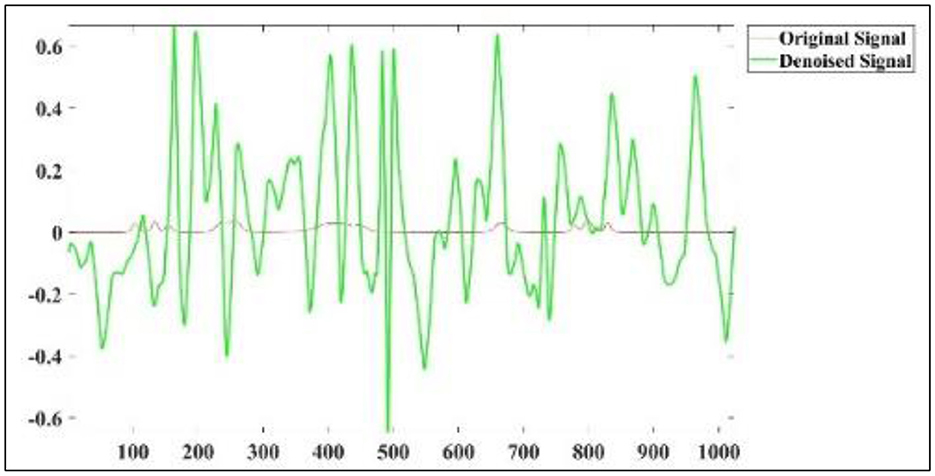
According to reference Locci et al. (2007), the bell-shaped WES is centered around the same frequency ranges. The data align well with theoretical predictions, owing to the consistent stability of the waveform. Figures 7A, B provide a comparative analysis of the estimated wave energy spectra (WES) for a given data series at different sampling rates. Specifically, the comparison focuses on horizontal displacements at a time index close to 1 s. Based on the analysis of two wavelet spectra obtained at an initial sampling rate of 2,048 Hz, it is seen that the predominant energy of the signal is concentrated in the higher frequency bands. This observation suggests the presence of withheld data inside the signal. Given that the original signal is under sampled and our objective is to see the whole frequency spectrum, it is possible for both sampling rates to be inaccurate, albeit the second rate is comparatively less erroneous. However, a comprehensive understanding of the horizontal deviation may be obtained by analyzing the data collected at a frequency of 1,024 Hz. Hence, a sample rate of around 1,024 Hz is deemed suitable as an initial value. The decision to refrain from oversampling is based on the understanding that augmenting the sampling rate will not provide any further insights into the frequencies under examination.
Continuing the discussion on the selection of an appropriate sample frequency for extracting harmonic features from a known signal using the Dual-Tree Complex Wavelet Transform (DTCWT) is 2,048 Hz. The signal that is now under consideration has been subjected to a decomposition process, namely up to the fourth level. The present study demonstrates that the accurate acquisition of harmonic-related information is not feasible. Based on the WES principle, it has been shown that a frequency of 2,048 Hz is not the optimal frequency for extracting harmonic-related information from a distribution system. The accompanying power spectrum graphic is also provided, although it fails to accurately represent the harmonic characteristics of the signal when sampled at a frequency of 2,048 Hz.
The selection of a sample frequency of 1,024 Hz has been made in accordance with the WES idea in order to extract the characteristics of harmonics. It is demonstrated that the known signal comprises the fundamental frequency as well as the 3rd, 5th, and 7th harmonics. Therefore, by collecting data with a sample frequency of 1,024 Hz, it is possible to extract accurate information. The Discrete Dual-Tree Complex Wavelet Transform (DTCWT) is a member of the wavelet family, known for its ability to extract frequency bands at various levels. The power spectrum method enables the precise identification of individual frequency components. The tables presented, namely Tables 2, 3, illustrate the diverse ranges of frequencies acquired by the Dual-Tree Complex Wavelet Transform (DTCWT). The purpose of this explanation is to elucidate the percentage of frequency bands effectively caught by the DTCWT.

Table 3. Various frequency bands extracted by DTCWT at various levels of decomposition when sampling frequency is 1,024 Hz.
7 Selection of decomposition level
MDL criteria is a crucial criterion for determining the optimal wavelet filter and “optimal” number of wavelet coefficients to be kept for signal reconstruction as in Equations (50) and (51).
Various ways exist among the community for detecting a sufficient number of clusters within a data collection. This research focused on a strategy on Minimum Length of Description.
The total length of a model may be determined by adding the encoding length of specific data, given the model, to the amount of information required to encode the model itself. A desirable model under the Minimum Description Length (MDL) framework is characterized by its ability to effectively encode data and possess an efficient description. This observation implies a potential relationship between MDL and the concept of learning as a means of data compression. In conclusion, it is essential to adopt a formal representation of the notion that the augmentation of model complexity should only be pursued if it leads to a commensurate enhancement in the descriptive capacity of our data, as per the Minimum Description Length (MDL) framework. In the above equation, X represents a vector including a set of data values. The function p(x) represents the density of the Gaussian mixture model (GMM) at a given location x. The first term in the equation corresponds to the negative log-likelihood of the data under this model, assuming K independent Gaussians. The expense associated with encoding the data, using Gaussian Mixture Models (GMM). The encoding cost of the generalized linear model is the second factor to consider. In the context of Gaussian Mixture Models (GMMs), the symbol P represents the total count of parameters that are accessible or assignable inside the model. Given a data dimension denoted as D, the equation P = K[D + D(D+1)/2] may be derived. In this equation, P represents the total number of parameters, K represents a constant, D represents the number of values for each mean vector, and D(D+1)/2 represents the number of values for each covariance matrix. Our objective was to use the identical Minimum Description Length (MDL) approach in order to get an optimal value for K inside the framework of a K-Medoids model. The challenge of MDL's application to K-Medoids is in determining its optimal form of adaptation. With K-Medoids, a distance metric is used to only organize the information. Unfortunately, the ability to characterize the data as a Gaussian mixture is not possible because there is no established vector algebra on data items.
However, depending on how the data is clustered, the distances between each data point and the nearest medoid are distributed differently. In this investigation, an MDL was determined using these distance data. If increasing the number of clusters (represented by K) has no effect on tightening this distribution, then doing so will result in an ever-rising description length for the distribution, suggesting that increasing the number of clusters does not lead to a better data model. The following formula for the length of a description is obtained using the MDL formulation for this concept: it is important to note that the first two terms are the same as in the previous equation, but the third term, The variable P represents the count of independent parameters associated with the distribution p(||x-cx||). This distribution characterizes the distances between each data element (x) and its closest medoid cx. Further details will be provided in the subsequent explanation. An additional term has been included to incorporate the computational complexity associated with the encoding of the K medoids.
Therefore, the data may be subjected to K-Medoids clustering using various K values. The MDL measure mentioned earlier can be applied to each model, and the model with the lowest description length L can be selected automatically (X).
As mentioned earlier, it is necessary to choose a form (or a collection of forms) for the distance distribution p(||x-cx||). The distance data has been modeled using a gamma distribution, and we are now using this distribution to calculate log-likelihood values. In my current implementations, I have set the value of P to 2, since the gamma distribution is characterized by two independent variables: the shape parameter and the location parameter. Further details on the rationale for selecting a gamma distribution as the preferred statistical model can be accessed in the following sources: reference 1 and reference 2. One further justification for my inclination is in the gamma distribution's adaptability, since it may be used to represent datasets exhibiting two-tailed, single-tailed, and/or exponential-like distributions. As previously stated, the selection of a form (or forms) is necessary for the distance distribution p(||x-cx||). Currently, log-likelihood values are being computed via the process of fitting a gamma distribution to the distance data. The gamma distribution is characterized by two independent parameters: a shape parameter and a location parameter. In current implementations, the value of P is set to 2.
It is important to consider that the gamma distribution utilized in this context exhibits a tendency toward cluster distributions that resemble Gaussian clusters. Consequently, its current behavior bears resemblance to that of the G-Means algorithm, which aims to identify clustering's that result in Gaussian distributions within each cluster. Given the absence of any persuasive rationale to priorities or presume Gaussian-like cluster distributions over all metric spaces, it is crucial for future research to explore the broader spectrum of potential distance distributions. However, despite the limitations of Gaussian distributions in accurately describing our data clusters, we are still able to get meaningful results using them. The gamma distribution's durability might perhaps be linked to its ability to include a diverse range of geometries.
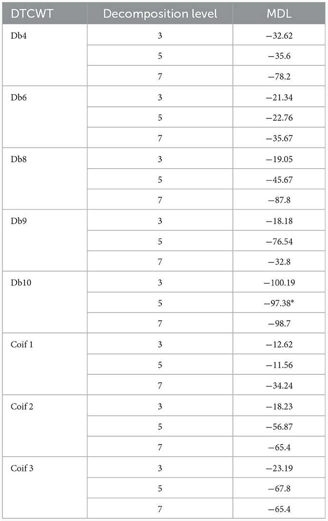
I will use examples from data sets well-suited to visual representation to show how the MDL-enhanced K-Medoids work. All the code I used to get these results is included here. Here's a dataset comprised of made-up 2D points to consider. Algorithms based on MDL are displayed in Table 4 and were used to identify the appropriate decomposition level and mother wavelet. There is a minimum detectable level (MDL) of−100.19 dB at level 3 with dB 10 in Table 4.
7.1 Case I: sinusoidal supply and single nonlinear load
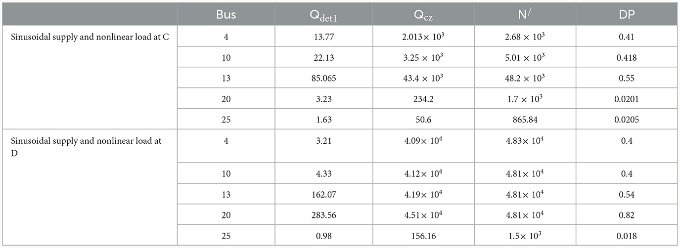
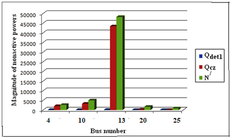
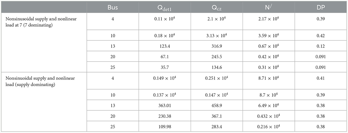
Here the supply is assumed to be pure sinusoidal. At first the nonlinear load at 13 is assumed to generate harmonics as nonlinear load is connected with this bus. Nonactive powers and detail pollution obtained from DTCWT analysis are shown in Table 5. It may be observed that Qcz is closer to N/than Qdet, up to node 13, which indicates that harmonic generating source is located at downstream side of the nodes 4, 10, and 13 and beyond node 13, Qcz is closer to Qdet i.e. harmonic generating source is located at the upstream side of the point of measurement. The grid is synchronized through adaptive grid forming control for voltage source converter and it is more discussed in Al-Shetwi et al. (2022). Control in convertors is achieved through staircase modulation, which ensure un interrupted power supply in the grid (Chappa et al., 2022). At node 13, the magnitude of DP is maximum indicating that the location of the harmonic source is at 13.
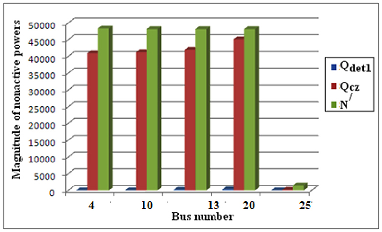
A bar chart of magnitude of nonactive powers at different buses is shown in Figure 9. It is observed that up to bus 13 difference between the Qcz and N/is lower than the difference between Qcz and Qdet1, i.e. up to bus 13, Qcz is closer to N/which means harmonic generating source is located at the downstream side of the bus 13. On the other hand, at bus 20 and 25, difference between the Qcz and Qdet1 is lower than the difference between the Qcz and N/i.e. Qcz is closer to Qdet1 than N/, which means harmonic generating source is located upstream side of node 20.
Now the nonlinear load is connected with node 20 which is indicated by the highest value of DP at node 20. From Table 5 it is observed that 20 is the dominant harmonic generating source, as up to 20, Qcz is closer to N/ and at node Y, Qcz is closer to Qdet1. Figure 9 shows that up to bus 20 the difference between the Qcz and N/is lower than the difference between Qcz and Qdet1. But at bus 25 difference between the Qcz and Qdet1is lower than the difference between Qcz and N/. Therefore, it is clear that bus 20 is the dominant source of harmonic generation.
The Time Frequency Response is plotted for the both signals of active power and non- active power. Time-frequency response plots are graphical representations that provide valuable insights into the behavior of a system in both the time and frequency domains. It is also important to plot signal power distribution through power spectrum curves; it gives the information of irregularity in the signal. In this case first data has been collected at 2048 Hz sampling frequency which is shown in Figure 10. But as per the Figure 11 proper characteristics frequencies cannot be collected. When we set sampling frequency is 1,024 Hz then distinguishable characteristics frequencies are extracted at different level of decomposition which is shown in Figure 12.
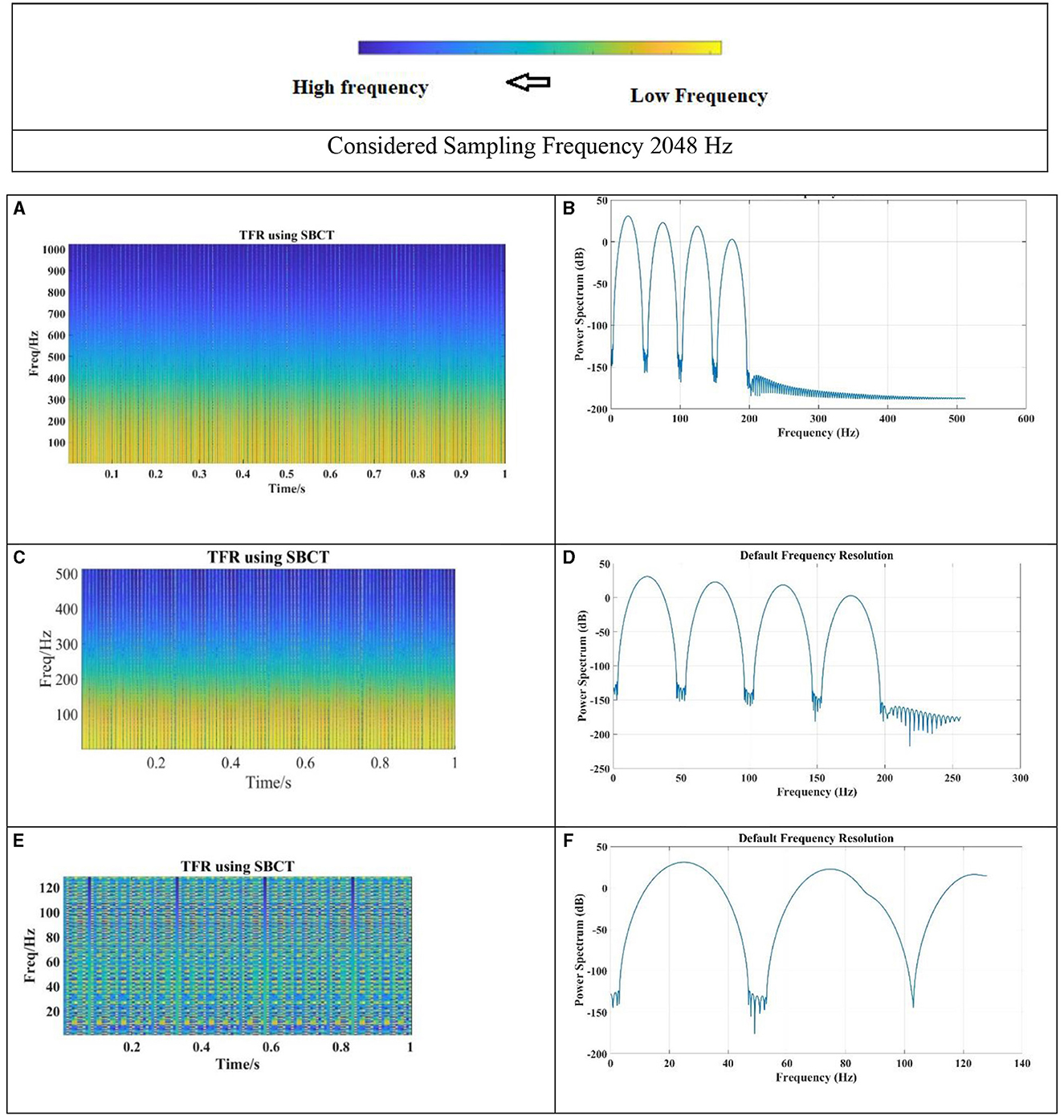
Figure 11. Single non-linear load at 7. (A) Signal of non-active power N/. (B) Power spectrum. (C) Signal of non-active power Qcz. (D) Power spectrum. (E) Signal of non-active power Qdet. (F) Power spectrum at level 3.
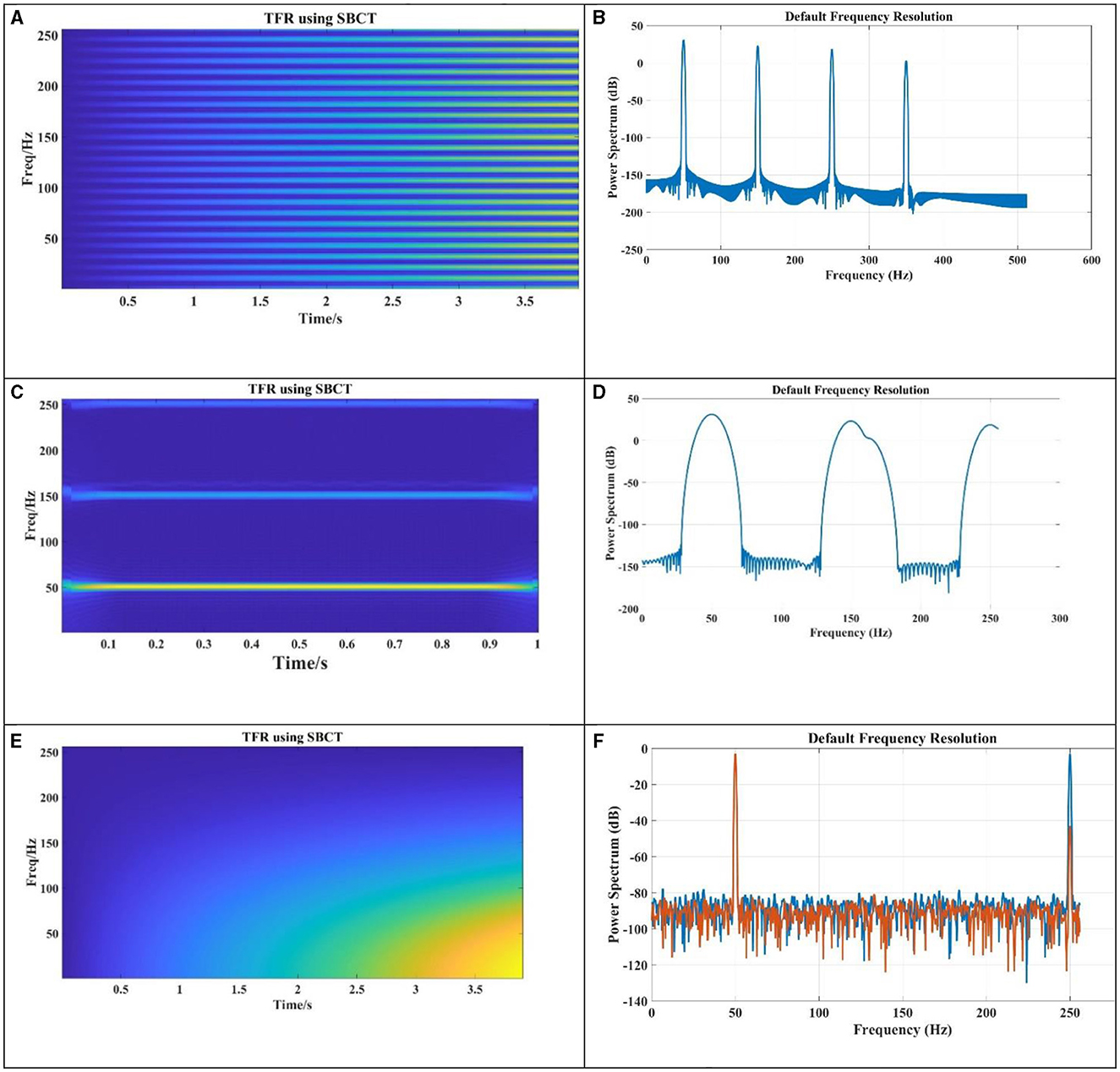
Figure 12. Nonlinear load at bus 7 and considered sample frequency is 1,024 Hz. (A) Captured frequency by DTCWT for Qdet. (B) Power spectrum for Qdet. (C) Signal of non-active power for Qcz. (D) Power spectrum for Qcz. (E) Captured frequency by DTCWT for N/. (F) Power spectrum for N/.
7.2 Case III: sinusoidal supply and nonlinear loads at node 7 and 9
In this case the supply is kept sinusoidal, but the loads at node 7 and node 9 are made nonlinear by connecting nonlinear load. The nonlinear load connected at node 7 is made the dominant source of harmonic pollution, as a result DP at node 7 is higher than DP at node 9.
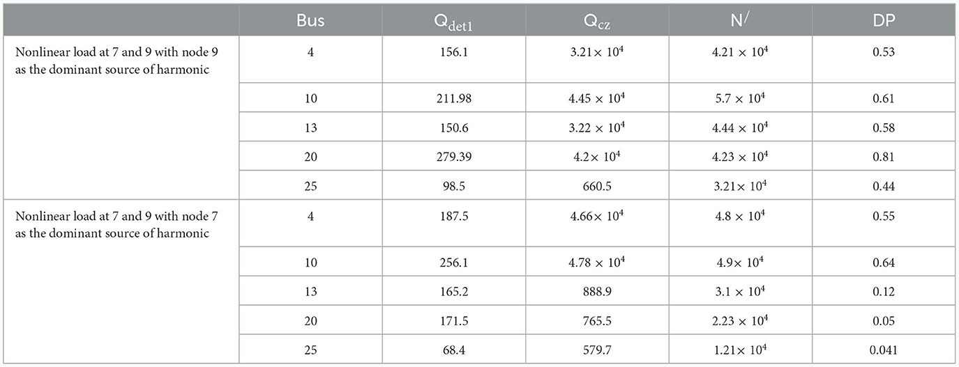
From Table 6 it is observed that when 7 is the dominant harmonic generating source Qcz is closer to N/upto node 7 and at node 9, Qcz is closer to Qdet1. A bar chart of magnitude of nonactive powers at different buses is shown in Figure 13. It is observed that up to bus 7 difference between Qcz and N/is lower than the difference between Qcz and Qdet1, i.e. up to bus 7, Qcz is closer to N/which means harmonic generating source is located at the downstream side of the bus 7. On the other hand at bus 9 difference between Qcz and Qdet1 is lower than the difference between Qcz and N/i.e. Qcz is closer to Qdet1 than N/, which means harmonic generating source is located at the upstream side of node 9.
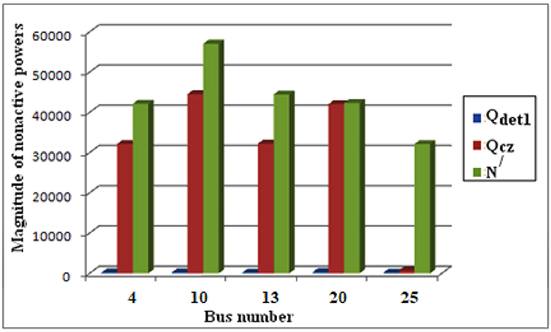
Figure 13. Bar chart of nonactive powers when nonlinear load is connected at 7 and 9 with node 9 as the dominant source of harmonic.
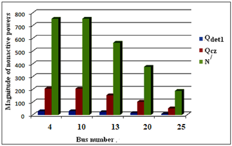
Now the nonlinear node at 7 is made the dominating harmonic generating source as indicated by the highest value of DP at node 7. From Table 6 it is observed that as 7 is the dominant harmonic generating source, so up to 7, Qcz is closer to N/ and at other nodes, Qcz is closer to Qdet1. Figure 14 shows that up to bus 7 the difference between Qcz and N/is lower than the difference between Qcz and Qdet1. But from bus 8, difference between Qcz and Qdet1is lower than the difference between the Qcz and N/. Therefore, it is clear that bus 7 is the dominant source of harmonic generation.
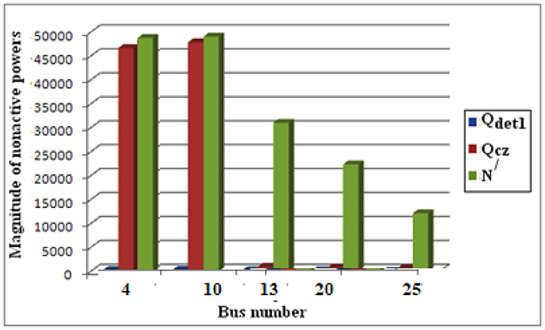
Figure 14. Bar chart of nonactive powers when nonlinear load is connected at 7 and 9 with node 7 as the dominant source of harmonic.
Table 6 provides the information regarding the magnitudes of non-active power quantities for the case III.
7.3 Case IV: nonsinusoidal supply and linear loads
This case deals with a nonsinusoidal supply containing higher order harmonic component of 15% of the fundamental voltage and linear loads. From Table 7 it can be seen that Qcz is always closer to the value of Qdet1 indicating that the source of harmonic is in the upstream side with respect to all the nodes of measurement. Figure 15 shows that up to bus 25 the difference between Qcz and Qdet1 is lower than the difference between the Qcz and N/. Therefore, it is also clear that supply is nonsinusoidal.
7.4 Case V: nonsinusoidal supply and nonlinear load
Next we consider nonsinusoidal supply which contains higher order harmonics component of 5% of fundamental voltage and a Nonlinear load at bus 7. The magnitude of harmonic current is 20% of fundamental current. The DP values at different nodes shown in Table 8 indicate that the nonlinear load at bus 7 is the dominant harmonic source. Hence Qcz is closer to N/at node 4 and node 7 which indicates that the source of harmonics is in the downstream side of node 4 and node 7. The corresponding bar chart is shown in Figure 17.
Now the supply contains harmonics and it is assumed to have 7th harmonic component which is 20% of the fundamental voltage along with nonlinear load at 7 which generates 5th harmonic current. The magnitude of 5th harmonic current is 5% of the fundamental current. From Table 8 it is seen that when DP value at node 4 is maximum i.e., supply is the dominant harmonic generating source, Qcz is closer to Qdet1 at each node which indicates the presence of dominating harmonic source at the upstream side of all the measuring points. Corresponding bar chart is shown in Figure 16. Captured harmonics for nonsinusoidal supply is showing in Figure 17.
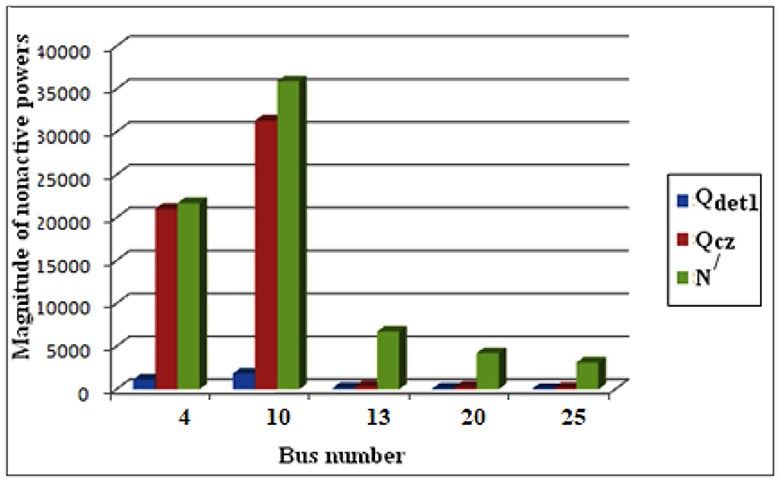
Figure 16. Bar chart of nonactive powers under nonsinusoidal supply and nonlinear load at 7 (nonlinear load dominating).

Figure 17. Captured harmonics for case V. (A) Captured frequency by DTCWT for Qdet. (B) Power spectrum for Qdet. (C) Captured frequency by DTCWT for Qcz. (D) Power spectrum for Qcz. (E) Captured frequency by DTCWT for N/. (F) Power spectrum for N/.
7.5 Case VI: resonance condition at the customer location
In this case study a resonance condition is created at node 13. To create resonance a capacitor with a capacitance of 1.32 × 10⁻⁴ F corresponding to 7th harmonic frequency has been connected with node 13 and a nonlinear load which generates 7th harmonic current is connected at node 20. From Table 9 it is seen that Qcz is closer to N/up to node D indicating that the source of harmonics is in the downstream with respect nodes 7, 10, 13 and 20. This shows that the proposed method is also valid for resonance condition. Hence if a customer creates resonance within his/her facility, this method will successfully identify the location of dominant harmonic source. Bar chart of this case study is shown in Figure 18.
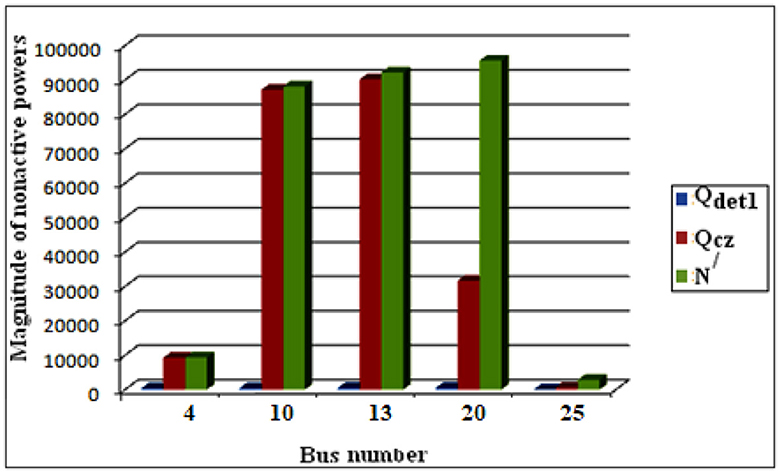
Figure 18. Bar chart of nonactive powers under sinusoidal supply and nonlinear load at 13 with resonance.
7.6 Case VIII: nonlinear loads generating equal amount of harmonics
If the nonlinear loads connected at two different nodes generate same number of harmonics, then |Qcz−Qdet1|= as discussed in article 2. Here nonlinear loads are connected at nodes 4 and 7. Both are generating 5th and 7th harmonic current in the system. The harmonic current contributed by each source is varied. The values of Qdet, Qcz and N/ at the measuring point C are shown in Table 10. When 4 is acting as the dominant source of harmonic i.e., DP at node 4 is higher than DP at node D, then it is observed that |Qcz−Qdet1| < at node C. When 13 is acting as the dominant source of harmonic then it is observed that |Qcz−Qdet1|> at node 13. When both node 7 and node 13 generate equal amount of harmonics, DP at 7 and 13 are equal and |Qcz−Qdet1|= at node 13. Figure 19 shows the pattern of captured harmonics.

Figure 19. Feature extraction of PHEV Truck. (A) Captured frequency by DTCWT for Qdet. (B) Power spectrum for Qdet. (C) Signal of non-active power QCZ. (D) Power spectrum for QCZ. (E) Captured frequency by DTCWT for N/. (F) Power spectrum for N/.
Figure 20 shows the graphical representation of vs. |Qcz−Qdet1| at the measuring point 13. When nonlinear loads present on both the upstream and downstream sides of the measuring point 13 generate equal amount of harmonics, then the points are on the same straight line. When node 7 acts as dominant harmonic source then the points lie on the upper side of the straight line as the dominant harmonic source is in the upstream side with respect to node 13. On the other hand when dominant source is connected with the downstream side i.e., at node D then the points lie on the lower part of the straight line.
The Proposed method is compared with methods that are existed in literature is given in Table 10.
8 Conclusions
The proposed single point strategy for harmonic source identification is designed to identify the dominant harmonic generating source in a network. It operates on both sides of the metering point, allowing for detection of the source's location. The method relies on comparing various non active power quantities that specifically represent the harmonic components present in the system during disturbances.
1. To validate the effectiveness of the proposed method, several case studies were conducted in a radial distribution network. The results of these studies demonstrated that the proposed method successfully detects the location of a harmonic source with 100% accuracy and 0.0002 ms fast in scenarios involving a single harmonic source. Additionally, it can identify the location of the dominant harmonic source when multiple sources are present.
2. Furthermore, the single point strategy remains valid even in situations involving resonance conditions and composite harmonic generating sources. This means that the method is robust and can accurately identify the primary source of harmonics, even in complex scenarios.
3. Proposed method also identifies harmonic sources location in noise condition and makes proposed method more reliable
4. Proposed method is compared with existed methods in literature and it outperformed other methods in both classification accuracy and detection speed. Therefore, proposed method is both accurate and fast to detect and locate harmonic sources.
By employing this single point strategy for harmonic source identification, system operators and engineers can better understand and mitigate harmonic issues in power distribution networks, leading to improved power quality and more efficient operation. While the identification of harmonic sources in smart grids using systematic feature extraction from non-active powers offers significant advantages, there are also potential drawbacks and challenges associated with this approach. It's essential to consider these limitations to develop a comprehensive understanding of the methodology. Some drawbacks include
1. Systematic feature extraction from non-active powers involves dealing with complex datasets and extracting relevant features. The process can be computationally intensive and may require sophisticated algorithms, which can pose challenges in terms of implementation and computational resources. But this drawback is reduced by selecting accurate level of signal decomposition through DTCWT.
2. The performance of the harmonic source identification system may be sensitive to changes in the smart grid environment. Factors such as the addition of new equipment, changes in load profiles, or alterations to the power distribution network may require frequent model updates and recalibration.
3. Implementing a robust harmonic source identification system requires investment in advanced sensors, communication infrastructure, and computational resources. Small-scale utilities or those with limited budgets may find it challenging to allocate resources for the deployment and maintenance of such systems.
Data availability statement
The original contributions presented in the study are included in the article/supplementary material, further inquiries can be directed to the corresponding author.
Author contributions
SJ: Conceptualization, Methodology, Investigation, Writing original draft, Writing—review & editing. PS: Conceptualization, Methodology, Investigation, Writing—original draft, Writing—review & editing. KP: Conceptualization, Methodology, Investigation, Writing—original draft, Writing—review & editing. SS: Conceptualization, Methodology, Investigation, Writing—original draft, Writing—review & editing. SP: Conceptualization, Methodology, Investigation, Writing—original draft, Writing—review & editing. GD: Conceptualization, Methodology, Investigation, Writing—original draft, Writing—review & editing. TU: Conceptualization, Methodology, Investigation, Writing—review & editing. All authors contributed equally to this work.
Funding
The author(s) declare that no financial support was received for the research, authorship, and/or publication of this article.
Conflict of interest
The authors declare that the research was conducted in the absence of any commercial or financial relationships that could be construed as a potential conflict of interest.
Publisher's note
All claims expressed in this article are solely those of the authors and do not necessarily represent those of their affiliated organizations, or those of the publisher, the editors and the reviewers. Any product that may be evaluated in this article, or claim that may be made by its manufacturer, is not guaranteed or endorsed by the publisher.
Footnotes
References
Achim, A., and Kuruoglu, E. E. (2005). Image denoising using bivariate α-stable distributions in the complex wavelet domain. IEEE Signal Process. Lett. 12, 17–20. doi: 10.1109/LSP.2004.839692
Al-Shetwi, A. Q., Issa, W. K., Ageil, R., Ustun, S., Al-Masri, H., Alzaareer, M., et al. (2022). Active power control to mitigate frequency deviations in large-scale grid-connected pv system using grid-forming single-stage inverters. Energies 15, 2035. doi: 10.3390/en15062035
Balci, M. E., and Hocaoglu, M. H. (2010). “A current resolution for fast measurement of power resolutions in non sinusoidal single phase systems,” in Proc. of Harmonics and Quality of Power 14th International Conf in Bergamo (Bergamo: IEEE), 26–29.
Borran, M. J., and Nowak, R. D. (2001). Wavelet-based denoising using hidden Markov models. Proc. IEEE ICASSP 6, 3925–3928.
Cataliotti, A., Cara, D. D., Emanuel, A. E., and Nuccio, S. (2011). Current transformer effects on the measurent of harmonic active powers in LV and MV networks. IEEE Trans. Power Deliv. 26, 360–368. doi: 10.1109/TPWRD.2010.2079336
Chappa, G. S., Rao, A., Dawn, K. D., and Ustan, T. S. (2022). Development of an enhanced selective harmonic elimination for a single-phase multilevel inverter with staircase modulation. Electronics 11, 3902. doi: 10.3390/electronics11233902
Chauhan, A., Khan, M. T., Srivastava, A., Tripathi, A., Hussain, S., and Ustun, T. (2022). Techno-economic assessment and environmental analysis of an optimal hybrid system under novel demand response scheme for a remote region of India. Energy Reports 8, 284–291. doi: 10.1016/j.egyr.2022.05.200
Chawda, G. S., Shaik, A. G., Shaik, M., Padmaban, S., Holm-Nielsen, J. B., Mahela, O. P., et al. (2020). Comprehensive review on detection and classification of power quality disturbances in utility grid with renewable energy penetration. IEEE Access 8, 146807–146830. doi: 10.1109/ACCESS.2020.3014732
Deng, W., Xu, D., Xu, D., and Li, M. (2021). “Detection and classification of power quality disturbances using variational mode decomposition and convolutional neural networks,” in 2021 IEEE 11th Annual Computing and Communication Workshop and Conference (CCWC), Nevada: IEEE, 1514–1518.
Gong, R., and Ruan, T. (2020). A new convolutional network structure for power quality disturbance identification and classification in micro-grids. IEEE Access 8, 88801–88814. doi: 10.1109/ACCESS.2020.2993202
Granados-Lieberman, D., Romero-Troncoso, R. J., Osornio-Rios, R. A., Garcia-Perez, A., and Cabal-Depez, E. (2011). Techniques and methodologies for power quality analysis and disturbances classification in power systems: a review. IET Gener. Transm. Distrib. 5, 519–529. doi: 10.1049/iet-gtd.2010.0466
Khoa, N. M., and Dai, L. V. (2020). Detection and classification of power quality disturbances in power system using modified-combination between the stockwell transform and decision tree methods. Energies 13, 3623. doi: 10.3390/en13143623
Khokhar, S., Mohd Zin, A. A., Mokhtar, A. S., and Zareen, N. (2016). Automatic pattern recognition of single and multiple power quality disturbances. Aust. J. Electr. Electron. Eng. 13, 43–53. doi: 10.1080/1448837X.2015.1092932
Kingsbury, N. G. (2001). Complex wavelets for shift invariant analysis and filtering of signals, Appl. Comput. Harmon. Anal. 10, 234–253. doi: 10.1006/acha.2000.0343
Latif, A. (2020). Price based demand response for optimal frequency stabilization in orc solar thermal based isolated hybrid microgrid under salp swarm technique. Electronics 9, 2209 doi: 10.3390/electronics9122209
Lin, L., Wang, D., Zhao, S., Chen, L., and Huang, N. (2019). Power quality disturbance feature selection and pattern recognition based on image enhancement techniques. IEEE Access 7, 67889–67904. doi: 10.1109/ACCESS.2019.2917886
Liu, D., Jin, T., Mohamed, M. A., and Wang, Q. (2021). A novel three-step classification approach based on time-dependent spectral features for complex power quality disturbances. IEEE Trans. Instrumentat. Measurem. 70, 1–14. doi: 10.1109/TIM.2021.3050187
Locci, N., Muscs, C., and Sulis, S. (2007). On the measurement of power- quality indexes for harmonic distortion in the presence of capacitors. IEEE Trans Instrum Measurem. 56, 1871–1876. doi: 10.1109/TIM.2007.903597
Mahafzah, K. A., Obeidat, M. A., Mansour, A. M., and Al-Shetwi, A. Q. (2022). Artificial-intelligence-based open-circuit fault diagnosis in VSI-Fed PMSMs and a novel fault recovery method. Sustainability 14, 16504. doi: 10.3390/su142416504
Mahela, O. P., Shaik, A. G., Khan, B., Mahla, R., and Alhelou, H. H. (2020). Recognition of complex power quality disturbances using s-transform based ruled decision tree. IEEE Access 8, 173530–173547. doi: 10.1109/ACCESS.2020.3025190
Masoum, M., Jamali, S., and Ghaffarzadeh, N. (2010). Detection and classification of power quality disturbances using discrete wavelet transform and wavelet networks. IET Sci. Meas. Technol. 4, 193–205. doi: 10.1049/iet-smt.2009.0006
Meena, H., Meena, H. K., and Saxena, D. (2022). “Classification of power quality disturbances with DWT based effective feature extraction,” in 2021 4th International Conference on Recent Trends in Computer Science and Technology (ICRTCST) (Jamshedpur: IEEE),314–320.
Morsi, W. G., and El-Hawary, M. E. (2007). Reformulating three-phase power components definitions contained in the IEEE standard 1459-2000 using discrete wavelet transform. IEEE Trans Power Del. 22, 1917–1925. doi: 10.1109/TPWRD.2007.899776
Özmen, B., and Biricik, S. (2019). “Harmonic current detection based on the dual-tree complex wavelet transform,” in 2019 2nd International Conference on Smart Grid and Renewable Energy (SGRE) (Doha: IEEE), 1–5.
Parvez, I., Aghili, M., Sarwat, A. I., Rahman, S., and Fahmida, A. (2019). Online power quality disturbance detection by support vector machine in smart meter. J. Mod. Power SDst. Clean Energy 7, 1328–1339. doi: 10.1007/s40565-018-0488-z
Premkumar, M., Jangir, P., Sowmya, R., Alhelou, H. H., Heidari, A. A., and Chen, H. (2021). MOSMA: multi-objective slime mould algorithm based on elitist non-dominated sorting. IEEE Access. 9, 3229–3248. doi: 10.1109/ACCESS.2020.3047936
Ra, P. K., Karmakar, G., Eddy, F. D. S., Krishnan, A., and Gooi, H. B. (2018). Dual Tree Complex Wavelet Transform based Detection of Power Quality Disturbances, 2018. IEEE Innovative Smart Grid Technologies - Asia (ISGT Asia), Singapore. pp. 1177–1182. doi: 10.1109/ISGT-Asia.2018.8467843
Reddy, D. M. J. B., Mohanta, D. K., and Sagar, K. (2014). A multifunctional real-time power quality monitoring system using stockwell transform. IET Sci. Meas. Technol. 8, 155–169. doi: 10.1049/iet-smt.2013.0091
Roy, B., Adhikari, S., Datta, S., Devi, J., Devi, A. D., Alsaif, F., et al. (2023). Deep learning based relay for online fault detection, classification, and fault location in a grid-connected microgrid. IEEE Access 11, 62674–62696. doi: 10.1109/ACCESS.2023.3285768
Safiullah, S., Rahman, A., Lone, S., Hussain, S., and Ustun, T. (2022). Robust frequency–voltage stabilization scheme for multi-area power systems incorporated with EVs and renewable generations using AI based modified disturbance rejection controller. Energy Rep. 8, 12186–12202. doi: 10.1016/j.egyr.2022.08.272
Sendur, L., and Selesnick, I. W. (2002). Bivariate shrinkage functions for wavelet based denoising exploiting interscale dependency. IEEE Trans. Signal Process. 50, 2744–2756. doi: 10.1109/TSP.2002.804091
Shaik, R. S., Kumar, R., Asif, M., and Dadav, D. (2022). “DTCWT-SVM based identification of single and multiple power quality disturbances, 2022),” in International Conference on Intelligent Controller and Computing for Smart Power (ICICCSP), Hyderabad, India, 01–06.
Song, I. K., Yun, S. Y., Kwon, S. C., and Kwak, N. H. (2013). Design of smart distribution management system for obtaining real-time security analysis and predictive operation in Korea. IEEE Trans. Smart Grid. 4, 375–382. doi: 10.1109/TSG.2012.2233769
Ulinuha, A., Masoum, M. A. S., and Islam, S. (2011). Hybrid genetic-fuzzy algorithm for volt/var/total harmonic distortion control of distribution systems with high penetration of non-linear loads. IET Gener. Transm. Distrib. 5, 425439. doi: 10.1049/iet-gtd.2010.0168
Vatansever, F. (2010). RMS and power measurement using the dual-tree complex wavelet transform. Sci. Res. Essays 5, 2645−2655. Available online at: https://academicjournals.org/article/article1380629978_Vatansever.pdf
Xu, D., Gao, D., Li, Z., and Lu, M. (2020). Detection and classification of power quality disturbances in distribution networks based on VMD and DFA. CSEE J. Power Ener. Syst. 6, 122–130. doi: 10.1016/j.ijepes.2023.109481
Xu, Q., Sun, Y., Li, Y., Ding, Y., Sun, K., Yin, S., et al. (2024). A generalized admittance criterion for dominant harmonic source determination without synchronous phasor measurements. Int. J. Electr. Energ. Syst. 155, 109481. doi: 10.1016/j.ijepes.2023.109481
Yan, W., Qunzhan, L. I., and Fulin, Z. (2019). Transient power quality disturbance denoising and detection based on improved iterative adaptive kernel regression. J. Mod. Power Syst. Clean Energy 7, 644–657. doi: 10.1007/s40565-018-0467-4
Ye, Z. -J., Izadi, M., Farajollahi, M., and Mohsenian-Rad, H. (2024). A remedy to losing time synchronization at D-PMUs, H-PMUs, and WMUs in event location identification in power distribution systems. IEEE Trans. Smart Grid. 15, 641–54. doi: 10.1109/TSG.2023.3277853
Yin, S., Sun, Y., Xu, Q., Sun, K., Li, Y., Ding, L., et al. (2024). Multi-harmonic sources identification and evaluation method based on cloud-edge-end collaboration. Int. J. Electrical Power Energ. Syst. 156, 109681. doi: 10.1016/j.ijepes.2023.109681
Zahariah, J. (2024). Hybrid aquila arithmetic optimization based ANFIS for harmonic mitigation in grid connected solar fed distributed energy systems. Electric Power Syst, Res, 226, 109898. doi: 10.1016/j.epsr.2023.109898
Keywords: Dual-Tree Complex Wavelet Transform (DTCWT), non-active powers, detail reactive powers, Czarneck's reactive power, harmonics
Citation: Joga SRK, Sinha P, Paul K, Sahoo S, Pani SR, Dei G and Ustun TS (2024) Identification of harmonic sources in smart grid using systematic feature extraction from non-active powers. Front. Smart Grids 3:1338774. doi: 10.3389/frsgr.2024.1338774
Received: 15 November 2023; Accepted: 04 January 2024;
Published: 31 January 2024.
Edited by:
Nikos Hatziargyriou, National Technical University of Athens, GreeceReviewed by:
Youcef Belkhier, École Navale, FranceSourav Diwania, KIET Group of Institutions, India
Wei Qiu, Hunan University, China
Copyright © 2024 Joga, Sinha, Paul, Sahoo, Pani, Dei and Ustun. This is an open-access article distributed under the terms of the Creative Commons Attribution License (CC BY). The use, distribution or reproduction in other forums is permitted, provided the original author(s) and the copyright owner(s) are credited and that the original publication in this journal is cited, in accordance with accepted academic practice. No use, distribution or reproduction is permitted which does not comply with these terms.
*Correspondence: Taha Selim Ustun, selim.ustun@aist.go.jp
 S. Ramana Kumar Joga
 Pampa Sinha
 Kaushik Paul3
  Taha Selim Ustun