Review of Physically Unclonable Functions (PUFs): Structures, Models, and Algorithms
 Fayez Gebali
 Mohammad Mamun
- 1Department of Electrical and Computer Engineering, University of Victoria, Victoria, BC, Canada
- 2National Research Council Canada (NRC-CNRC), Government of Canada, Fredericton, NB, Canada
Physically unclonable functions (PUFs) are now an essential component for strengthening the security of Internet of Things (IoT) edge devices. These devices are an important component in many infrastructure systems such as telehealth, commerce, industry, etc. Traditionally these devices are the weakest link in the security of the system since they have limited storage, processing, and energy resources. Furthermore they are located in unsecured environments and could easily be the target of tampering and various types of attacks. We review in this work the structure of most salient types of PUF systems such as static RAM static random access memory (SRAM), ring oscillator (RO), arbiter PUFs, coating PUFs and dynamic RAM dynamic random access memory (DRAM). We discuss statistical models for the five most common types of PUFs and identify the main parameters defining their performance. We review some of the most recent algorithms that can be used to provide stable authentication and secret key generation without having to use helper data or secure sketch algorithms. Finally we provide results showing the performance of these devices and how they depend on the authentication algorithm used and the main system parameters.
1 Introduction
The Internet of Things (IoT) is now an essential component of many infrastructure systems such as healthcare delivery (telehealth), commerce, entertainment and military. Such systems are naturally a target for many types of attacks such as ransomeware, denial of service, data theft, data poisoning, etc. The weakest link in IoT systems are the edge devices which have the following weaknesses:
1. Located in uncontrolled or unsecured locations
2. Subject to different attacks such as theft, tampering, reverse engineering, and side-channel attacks
3. Low storage, processing and energy resources
4. Vulnerability to storing secret passwords and session keys in nonvolatile random access memory (NVRAM)
5. Primitive or non-existent operating systems
All the above weaknesses can be reduced or eliminated by adding PUF modules to such IoT edge devices. PUFs are inexpensive hardware modules that allow IoT edge devices to be immune to tampering and to have unique identities (IDs) that can not be forged or duplicated and can be used for authentication and secure secret key generation. The inclusion of PUFs allows the edge devices to generate stable secret session keys that can not be reverse engineered or forged.
Figure 1 shows a telehealth system as a representative infrastructure system that uses IoT edge devices. The main agents in the system include: System server (top of figure), Gateway G (left of figure) that connects the simple edge devices to the internet, IoT edge devices D (bottom left of figure) comprising sensors and actuators, and medical health professionals (bottom right of figure) accessing the system through remote mobile devices M (right of figure). The dataset (top left of the figure) stores the unique challenge/response pairs (CRP) associated with each IoT edge device. Typically this dataset is kept by a trusted certification authority (CA). This data is prepared and supplied by the device manufacturer.
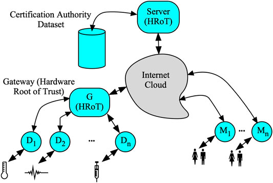
FIGURE 1. Telehealth IoT system.
The server could be considered as a hardware root of trust (HRoT) since it has layered security precautions including software, hardware and physical security. On the other hand, the weakest link in the telehealth system is the IoT edge devices due to the limitations discussed earlier.
Main Contributions: The main contributions of this work are summarized as follows:
1. Review of five main types of PUFs commonly used in IoT edge devices.
2. Develop novel statistical models for the five main PUF types taking into account random process variations (RPV), the three sources of noise in CMOS transistors and measurement noise.
3. Propose novel algorithms for measuring the statistical parameters of the PUFs by the IoT device manufacturer.
4. Discuss three PUF-based authentication algorithms. Two of these algorithms are new and never before published in the literature. One of the proposed algorithms uses the statistical distribution of the oscillators to ensure that the device response is noise-free without using the helper data algorithm.
Organization: The remainder of this work is organized as follows. In Section 2 a review of related works of five main PUF types is provided. In Section 3 the structures of the five main PUF types is reviewed and their operation to obtain CRP is discussed. In Section 4 statistical models for the five main PUF types is discussed. In Section 5 we discuss the methods used to transform the physical response of a PUF to a digital signature to distinguish between valid and counterfeit devices. In Section 6 we discuss the procedure to be used by the device manufacturer to obtain the standard golden response of a PUF when a particular challenge is applied. In Section 7 three types of algorithms for obtaining the CRPs are discussed and compared. In Section 8 the performance of four types of PUFS is provided. In Section 9 a comparison of the four simulated PUFs is provided. In Section 10 conclusions and recommendations are provided.
2 Related Works
An authentication and key exchange protocol for smart home IoT system was recently proposed in Fakroon et al. (2021), Fakroon et al. (2020). The protocol used a multifactor authentication algorithm to preserve user anonymity and untraceability. In Fakroon et al. (2020), the IoT edge devices were assumed to have secret keys stored in NVRAM. Fakroon et al. (2021) employed a PUF that gave the IoT edge devices unique identities (IDs). The authors analyzed the proposed schemes through formal analysis using the Burrows-Abadi-Needham logic (BAN), informal analysis and model check using the automated validation of internet security protocols and applications (AVISPA) tool. Security protocols using PUFs were first proposed in Delvaux et al. (2014); Delvaux (2017a); Delvaux 2017b, Dodis et al. 2008; Dodis et al., 2004 and Maes (2013); Maes et al. (2012, 2009).
An excellent source for study of PUFs is found in Maes (2013); Delvaux et al. (2014); Delvaux (2017a). The placement of PUFs in the overall information security framework is discussed as being the basis for providing physical security through providing a physical root of trust. Extensive overview of PUF structures is provided as well as definitions of the PUF properties is also provided.
Gassend et al. (2002) discussed delay-based PUFs such as arbiter PUF and ring oscillator PUF. The authors also discussed helper data which is used to generate stable, high-entropy session keys from PUF responses.
Studying the literature, several conclusions can be inferred about current state of the art in using PUFs for IoT authentication and secure key exchange:
1. Only one algorithm for issuing the CRP pairs is used: the single-challenge algorithm. This is a simple algorithm that does not utilize the IoT device statistical characteristics to advantage. Further, the response is sent in the clear to the authenticator to verify the device. This perhaps is the reason why authors preferred using strong PUFs and requiring that a challenge must be used only once to prevent obvious replay and impersonation attacks.
2. The parameters that define the response of the IoT PUF device were not identified explicitly in the published works. General statements are typically stated such as: “large number of response bits are needed to differentiate valid from counterfeit devices.”
3. Design of the PUF circuit parameters and their impact on the device’s statistical parameters were not identified nor studied to optimize the PUF performance.
3 Physically Unclonable Functions Structures
We provide in this section a brief view of the structure of the five most common types of PUFs. The main two applications of a PUF is for authenticating a device and to securely generate secret keys. A PUF can be thought of in general as a circuit element that generates a response r when a challenge c is applied:
In general, c is a vector of challenge bits and r is also a vector of response bits.
Assume Bc as the number of bits of the challenge vector c. A large value of Bc indicates a large number of independent challenges which characterizes a strong PUF. Conversely, a small value of Bc indicates a small number of independent challenges which characterizes a weak PUF. Be as it may, both strong PUFs and weak PUFs inherently have small entropy in their responses to be able to distinguish between counterfeit and valid devices. However, secret keys must have large entropy to provide a wide selection of keys. This requires processing the response r to generate the secret key K. The processing requires some form of error correcting coding and hashing.
Assume Br as the number of bits of the response vector r. A large value of Br is necessary to distinguish between valid and counterfeit devices. Exactly what is the acceptable value of Br is not well defined since it depends on both the manufacture details of the PUF and the algorithm used to apply the challenges c. These points are studied in this review for four different types of PUFs that are most commonly used in practice.
3.1 Static Random Access Memory Physically Unclonable Functions Structures
A static random access memory (SRAM) PUF is based on standard SRAM technology with the modification that the reset state is when each storage cell in the SRAM is placed in a basically unstable state. Traditional SRAM structure assumes the reset state places 0 in all storage cells. Obviously such SRAM would not be useful as a PUF. A proposed cell architecture is shown in Figure 2. Notice that the 6-transistor cell is now replaced with a 9-transistor cell. An extra reset input R is introduced so that when R = 1 both outputs of the cell is 0, which is an inherently unstable state. As soon as R is de-asserted, the cell switches to store 1 or 0 depending on the minute differences of the two sides of the cell. This cell was simulated using the analog device simulator QUCS Jahn and Borrás (2007) to show its operation when the symmetry of the transistors was slightly varied to show the tendency of the cell to initiate its value to 0 or 1. An SRAM PUF might have to be reset over 1,000 or more times to obtain dependable response free of CMOS noise and measurement noise. In general the basic SRAM can be placed in an unstable state in several ways.
1. Disconnect then reconnect the power supply VDD. This will force the initial state of the two outputs of the cell to be 0 simultaneously. This, however, might be a slow process since the power supply rails have a large parasitic capacitance.
2. Ground the bit lines
3. Modify the basic 6-transistor cell structure. An example of this approach is shown in Figure 2.
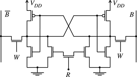
FIGURE 2. Detail of the basic architecture of NOR gate-based SRAM PUF.
These approaches require that the ASIC or FPGA designs be modified to allow for these operational modifications.
3.2 Ring Oscillator Physically Unclonable Functions Structure
Figure 3 shows a ring oscillator system used as a PUF. The system consists of W ring oscillator circuits and each ring oscillator circuit contains S inverters connected back-to-back, where S is the number of inverter stages and must be an odd integer.
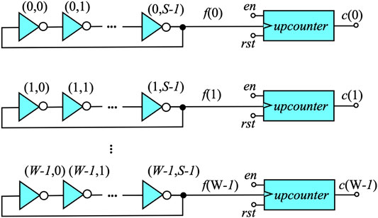
FIGURE 3. Ring oscillator array used as a PUF (RO-PUF).
To conserve power, an enable signal en is used to activate the RO system when a response is required during authentication. Otherwise, the system would be continuously operating. The oscillation frequencies f(w), with 0 ≤ w < W, are measured through upcounters that are triggered by the rising edges of the connected RO pulses. To measure and compare the frequencies, a timebase must be established that is independent of environmental variations and lack of providing an stable clock that functions the same during fabrication and in the field. Obviously this is extremely difficult to achieve on a practicable base. A preferred approach is to define a reference counter value cref that is chosen as part of the authentication process. The manufacturer will select one RO circuit to act as the timebase. Assume this counter is at row j. In that case the system operates until c(j) = cref and then the counter values are used to encode the B-bit response word r.
3.3 Enhanced Configurable Ring Oscillator Physically Unclonable Functions
A standard RO PUF offers a limited number of possible CRP options based on two parameters: the number of RO rows W in Figure 3 and the number of inverter stages S. The number of possible challenges is estimated as
In order to increase the CRP space and hence improve security we propose a modified RO derived form a Galois linear feedback shift register (LFSR). A complementary design can be found in Garcia-Bosque et al. (2020). In the design of Garcia-Bosque et al. (2020) the inverters and XOR gates are connected in series and are always in the path of the system. Our proposed design uses the inverters and XNOR gates that are connected in parallel as shown in Figure 4.
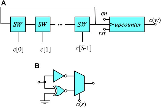
FIGURE 4. Highly configurable RO array used based on Fig. S3. (A) Introduction of configurable switch boxes SW between the inverters in all RO rows. (B) Structure of the switch box (SW).
Figure 4A shows the proposed RO system where we have S-stages and each stage is a selectable design based on the selection word c(s).
Figure 4B shows the details of each SW stage which selects between the delay of an inverter or an XNOR gate.
The number of CRP pairs can now be expressed as
where it was assumed that we only had B+ 1 rows. If we had W rows, the number of CRP is increased to
The following CRP generation strategy is adopted to generate a strong PUF out of the RO PUF that is immune to thermal noise and environmental variations:
1. Thermal noise is removed by using a long observation time which translates to a large observed upcounter value cobs.
2. Since establishing a common time base is difficult in the face of no global synchronization, we replace the time base with an observation counter value cobs. The upcounter is clocked by its own ring oscillator system and generates the reference upcounter value cref. The comparator compares this value with the observation counter value cobs supplied by the server/authenticator. As long as cref < cobs the enable output en is asserted to allow the RO system to operate. When cref = cobs the enable output en is 0 to stop the RO system. This indicates the response of the PUF is ready for measurement.
3. An address vector a is used to select B counters to generate a B-bit response vector r. The elements of a are randomly selected from among W oscillators. This gives
4. Environmental variations are overcome by basing the RO response on a comparative evaluation of counters in the same IoT device. This is done by comparing the chosen reference counter cref with the other B counters to remove the effect of environmental variations.
3.4 Arbiter Physically Unclonable Functions Structure
Arbiter PUF is a delay-based PUF as shown in Figure 5. A typical system will have W rows and each row has S 2 × 2-switching stages and an SR latch or D-type flip-flop (D-FF) acting as the arbiter. When bit c(j) = 0, the switching stage is in the straight through setting where the signal at the upper input is routed to the upper output. The signal at the lower input is routed to the lower output. When bit c(j) = 1, the switching stage is in the cross setting where the signal at the upper input is routed to the lower output. The signal at the lower input is routed to the upper output.
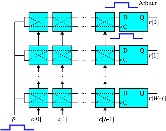
FIGURE 5. Structure for an arbiter PUF consisting of W arbiter rows and S 2 × 2-switching stages per row.
The procedure for obtaining CRP data proceeds as follows:
1. The challenge word c is chosen which consists of S bits to configure the state of the switching stages.
2. A pulse p is issued to all the arbiter rows.
3. B bits are selected to check the content of the output arbiters and this is considered the response r.
One serious problem with arbiter PUF is metastability since the upper output of the switch stage at location S − 1 is used as the data input to the RS flip-flop or D-type FF. The lower output is used to clock the D-FF. Under ideal circumstances, these two signals will have their rising edges arriving at the same time or very close to this. This will violate the setup and hold timing restrictions. Therefore, it is to be expected that several of the response bits will be undetermined or noisy. Several solutions have been proposed for this metastability issue such as the works in Machida et al. (2015); Alkatheiri and Zhuang (2017); Zalivaka et al. (2019); Ebrahimabadi et al. (2021); He et al. (2020); Tang et al. (2020).
3.5 Coating Physically Unclonable Functions Structure
A coating PUF is constructed by adding an insulating dielectric layer over the passivation layer of the integrated circuit (IC) Tuyls et al. (2006). This insulating layer could be deposited using Poly methyl methacrylate (PMMA). The insulating layer is now used to build capacitors at different locations on the surface of the IC. Figure 6 shows the structure of one capacitor.
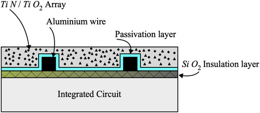
FIGURE 6. Cross-section of a capacitor PUF build using the protective coating at the surface of the IC.
The insulating layer is modified through mixing into it particles of Ti N and Ti O 2 in a random fashion. These particles perturb the relative dielectric constant ɛr of the coating in a random fashion. When identical capacitors are constructed on different integrated circuits (ICs), the resulting capacitances will have random values centred around an average nominal value:
where C0 is the nominal capacitance value, G (⋅) is Gaussian normal distribution, μp and σp are the mean value and standard deviation of the random process variations.
The structure of one coating PUF comb-shaped capacitor placed at the top of an IC is shown in Figure 7. Care must be exercised in choosing the physical parameters of the comb structure. A capacitor with large dimensions would average out the random ɛr variations and little differentiation is exhibited among the capacitors in different ICs or on the surface of the same IC.
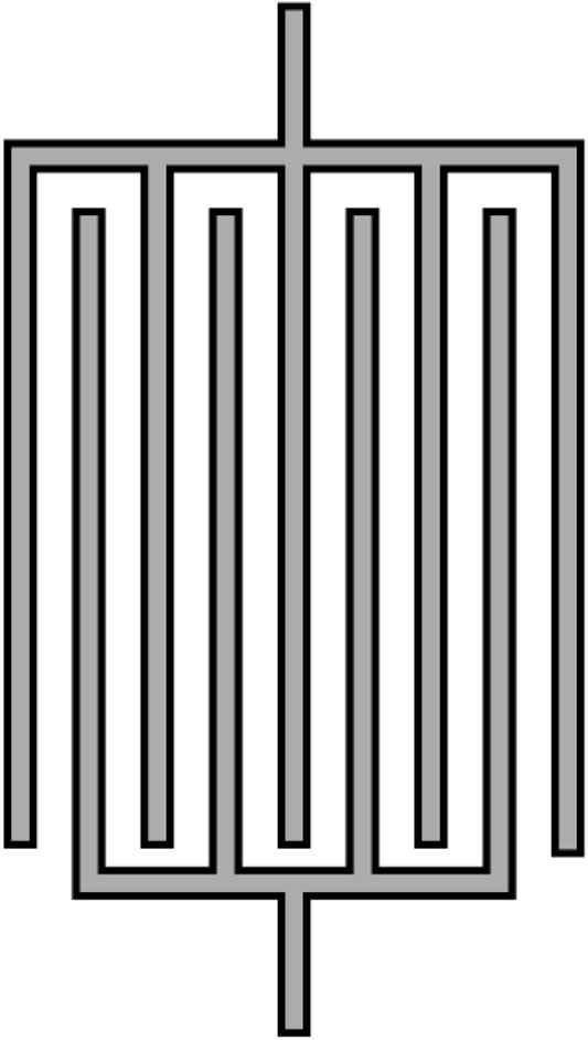
FIGURE 7. A view of the coating PUF comb-shaped capacitor placed at the surface of an IC.
3.6 Dynamic Random Access Memory Physically Unclonable Functions Structure
A dynamic random access memory (DRAM) is used in many computing systems due to its high storage capacity. This memory must be constantly refreshed on periodically every 50–100 ms. It must also be refreshed after every read/write operation. A DRAM system has also been used as a PUF Hashemian et al. (2015), Keller et al. (2014); Sutar et al. (2016, 2018); Tang et al. (2017).
The basic one-transistor (1-T) DRAM cell structure is shown in Figure 8. Similar to an SRAM, access to the stored bits is accomplished through the row decoder and column decoder. The simplest structure to store a bit is through an access nMOS transistor that charges the parasitic capacitor with the bit value.

FIGURE 8. DRAM memory structure.
The basis of operation of DRAM Cell is the decay of the charge in the parasitic capacitor. In order to develop a stored charge decay model, it is important to obtain an accurate circuit-level representation of the 1-bit cell. Figure 9 shows the desired circuit-level model.
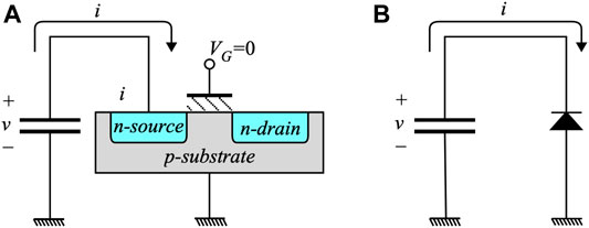
FIGURE 9. DRAM one-bit circuit-level model.
The striking result of this model is that the charge decays linearly with time and not exponentially with time as might be wrongfully deduced when the actual circuit is not correctly identified. We can see from the figure that the reverse bias current of the junction formed by the nMOS n-type source and p-type substrate. We can write the decay value of the capacitor voltage at time t is given by:
where T is the DRAM time constant of the cell voltage, i is the pn-junction leakage current and C is the parasitic capacitance value. The random variable i corresponding to pn-junction saturation current is given by Honsberg (2021):
where q is the electron charge, A is the pn-junction area, D is the diffusion constant of the minority carriers, L is the minority carrier diffusion length, ND is the doping level, and ni is the intrinsic carrier concentration.
4 Statistical Models of Physically Unclonable Functions
In this section we develop statistical models for the five types of PUFs reviewed in this work.
4.1 Static Random Access Memory Physically unclonable functions Statistical Model
The random variable chosen for modeling SRAM PUF is the probability a that the cell stores 1 after exiting an unstable state. When complete structural symmetry is achieved, ideal value of a becomes μp = 0.5. We can write a as the sum of two random processes:
where ap is due to static random process variation (RPV) and an is due to dynamic CMOS noise.
Central limit theorem implies that the random variable ap follows the biased Gaussian distribution whose pdf is given by:
where μp is the mean and
In addition to RPV, there are several sources of dynamic CMOS noise:
1. Thermal noise represented as an additive white Gaussian noise (AWGN) showing flat spectral distribution
2. Shot noise due to charge carrier flow across semiconductor junctions showing flat spectral distribution
3. Flicker noise due to charge trapping centres in the semiconductor bulk showing 1/f spectral distribution
The pdf of the dynamic noise an follows a zero-mean Gaussian distribution and is given by:
where
The pdf of combined RPV and CMOS noise for a specific PUF is given by:
where ap is the contribution of RPV and σn is the contribution of the CMOS noise.
4.2 Ring Oscillator Physically Unclonable Functions Statistical Model
The random variable chosen for modeling RO PUF is the inverter delay τ. We can write τ as the sum of two random processes:
where τp is due to static RPV and τn is due to dynamic CMOS noise.
Random variable τp follows the biased Gaussian distribution whose pdf is given by
where μp is the mean and
The pdf of the dynamic noise τn is given by
where
The pdf of combined RPV and CMOS noise for a specific PUF is given by:
where τp is the contribution of RPV and σn is the contribution of random thermal noise.
Assuming τ(w, s) represents the rise or fall time of the inverter at row w and column s, the frequency of oscillation of the ring oscillator in row w is given by:
where Tobs is the observation time given to allow the upcounters to count serveral RO cycles, f(w) is the oscillation frequency of row w and T(w) is the total delay through the S oscillators in row w. Random process variations (RPV) and CMOS noise ensure τ(w, s) is unique to each inverter in a given IoT device and across all the devices.
4.3 Arbiter Physically Unclonable Functions Statistical Model
The random variable chosen for modeling arbiter PUF is the single switching stage delay τ in the upper or lower outputs. We can write τ is the sum of two random processes:
where τp is due to static random process variation (RPV) and τn is due to dynamic CMOS noise.
The variable τp follows the biased Gaussian process whose pdf is given by:
where μp is the mean and
The variable τn follows a zero-mean Gaussian process
where
The combined effects of RPV and CMOS noise for a specific PUF generate a pdf given by:
where τp is the contribution of RPV and σn is the contribution of dynamic random CMOS noise.
The total delay of a ring-oscillator is the sum of S switching stages is given by:
the first moment, or expected value, for the delay of the arbiter PUF is:
The second moment of the arbiter PUF delay is given by:
The variance of the total delay can be found as:
4.4 Coating Physically Unclonable Functions Statistical Model
The random variable chosen for modeling coating PUF is the capacitor value C. We can write c as the sum of two random variables:
where Cp is due to static RPV and Cn is due to dynamic measurement noise.
The variable Cp follows the biased Gaussian process whose pdf is given by:
where μp is the mean and
The variable Cn follows a zero-mean Gaussian process
where
The combined effects of RPV and measurement noise for a specific PUF generate a pdf given by:
where Cp is the contribution of RPV and σn is the contribution of dynamic measurement noise.
4.5 Dynamic Random Access Memory Physically Unclonable Functions Statistical Model
From Eq. S8 we can identify two independent random variables for the rate of change of parasitic capacitor voltage: i and C. The variable i depends on physical, geometric and thermodynamic parameters as such can be described by static and dynamic contributions:
where ip is due to static random process variations and in is due to dynamic thermal noise and CMOS noise.
On the other hand, the random variable C is due solely due to geometric effects such as wire length and width and spacing between conducting layers. Therefore C depends only on static random process variations.
We choose the decay time constant T as the random variable describing the rate of charge decay. Ignoring second-order effects, we can therefore write the random variable T as.
For a given bit, the value of T will follow the Gaussian distribtution:
It is important to find a time value t such that on average, the capacitor voltage equals 0.5VDD in Eq. S6 since at this time approximately one-half of the bits will be 1 and the other half 0:
Thus t0 is found as:
The value of T can be estimated through a test structure by measuring v at a given time and using the equation:
It should be mentioned that the values of t, μp, σp and σn are measured in terms of the local clock cycle period. This ensures that effects of environmental variations are contained.
5 Digital Encoding of the Physically Unclonable Functions Response
The most important step in a PUF operation is the ability to translate the PUF response r to a digital signature for distinguishing between valid and counterfeit devices. We review in this section the different methods used to digitize the response for the four different PUF structures covered here.
5.1 Encoding of the Static Random Access Memory Physically Unclonable Functions Response
The response of the SRAM PUF is the content of the words of memory. Therefore the response is already in digital form and no need for further processing is needed.
5.2 Encoding of the Ring Oscillator Physically Unclonable Functions Response
Generating a digital signature from the response of the RO PUF starts by following these steps:
1. A reference oscillator is chosen which generates the reference counter value cref.
2. B oscillators are chosen and their count values c(j) are measured with 0 ≤ j < B.
3. Response bit rj is calculated as follows:
5.3 Encoding of the Arbiter Physically Unclonable Functions Response
Generating a digital signature from the response of the Arbiter PUF is obtained directly by choosing B arbiters. The arbiter outputs r(j) are measured with 0 ≤ j < B. The values obtained represent the desired response.
5.4 Encoding of the Coating Physically Unclonable Functions Response
Generating a digital signature from the response of the RO PUF starts by following these steps:
1. A reference capacitor is chosen which generates the reference capacitance value Cref.
2. B capacitors are chosen and their values C(j) are measured with 0 ≤ j < B.
3. Response bit rj is calculated as follows:
6 Establishing Physically Unclonable Functions Biometrics by the Device Manufacturer
To be able to use the PUF for authentication and secure key exchange, it is required to obtain the unique device characteristics by the manufacturer then sharing these characteristics with a trusted certification authority (CA). The procedure to be followed by the manufacturer to obtain the golden response rg of each device proceeds as follows:
1. A set of challenge words
2. A chosen challenge word
3. At iteration n, the response r(n) defining the PUF output is measured.
4. The average or golden mean value μg = < r(n) > and variance
5. The encoding scheme associated with the PUF is used to obtain the golden response rg = PUF_Encode (μg). For example the encoding scheme for the SRAM PUF is given by:
6. The golden variance value
7 Physically Unclonable Functions Authentication Algorithm
We discuss in this section three algorithms to authenticate a PUF device both by the manufacturer after device fabrication and in the field where the device is deployed.
7.1 Single-Challenge Algorithm
In the Single-Challenge Algorithm, the server, or the device fabricator, selects a specific challenge c. For example, in an SRAM PUF, the challenge is expressed as a which is an address of the SRAM. The word associated with this address is the resulting response. If more response bits are needed from the SRAM PUF, then the challenge would be a collection of addresses that need not be contiguous. The concatenation of the response words form the response bits r.
Algorithm 1 illustrates the single-challenge algorithm when applied to a RO PUF as an example.
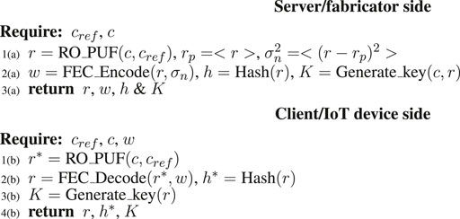
Algorithm 1. Single-challenge algorithm when applied to a RO PUF.
The details for the server/fabricator in Algorithm 1 are:
L1(a): Server selects parameters for CRP: cref and c to obtain the device response r after fabrication.
L2(a): Server generates helper data w, hash for authentication h, and session secret key K. The has value and secret key could depend on several parameters to ensure context-aware authentication or adaptive authentication.
L3(a): Server creates a PUF database that includes cref, c, r and w
The details of the client/IoT device operation in the field for Algorithm 1 are:
L1(b): Client applies challenge c to the PUF to obtain the noisy response r*
L2(b): Client uses the helper data w to remove the noise from r* and obtain noise-free response r. Using r, the client obtains the hash value h to be used for authentication.
L3(b): Using the estimated r, the client obtains the session key K to be used for coding and decoding of data.
7.2 Repeated-Challenge Algorithm
The basic idea behind the Repeated-Challenge Algorithm is to eliminate the dynamic random CMOS noise and measurement noise by repeating the steps used by the manufacturer to obtain the golden response.
Algorithm 2 illustrates the single-challenge algorithm when applied to a RO PUF as an example.
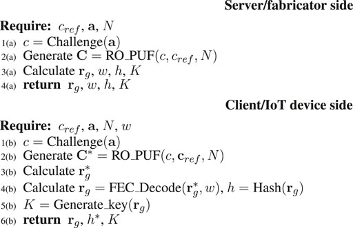
Algorithm 2. Repeated-challenge algorithm when applied to a RO PUF.
At the server after device fabrication, the following steps are performed:
L1(a): Server generates the challenge word based on address vector a
L2(a): Server generates the (B+ 1) × N matrix C
L3(a): Server calculates golden response rg, as well as w, h and K
L4(a): Server prepares the authentication database consisting of rg,
At the client side in the field, the following operations are performed:
L2(b): Client calculates the counter values matrix C*
L3(b): Client calculates the average response
L4(b): Client calculates corrected averaged response rg and corresponding hash value h
L5(b): Client calculates the session secret key k
7.3 Repeated-Challenge With Bit Selection Algorithm
The repeated-challenge with bit selection algorithm is derived from the repeated-challenge algorithm. The main idea of this algorithm is to consider or select the response values that have high SNR in a further attempt to reduce effects of CMOS noise. This selection is based on the statistical properties of the individual PUF modules in the system. For the case of an RO PUF as an example, the RO rows to be eliminated are those that have low SNR. The criterion to select a response bit to be part of the filtered response is based on the difference in counter the RO values. Given a collection of B counters c used to construct the response r.
The algorithm for selecting a counter to generate the reduced response for the case of a RO PUF is shown in Algorithm 3.
L2(a): Server exercises the device to generate the counter matrix C for all iterations N
L3(a): Server
L4(a): Server prepares empty arrays to represent the reduced address vector a, counters c, and response r
L5(a): Server selects the averaged reference counter value cref based on the address vector a
L6(a): Server calculates average golden response rg, standard deviation σc, helper data w, hash value h and secret session key K
L7(a)–13(a): Server scans all the B counters used to generate the response and select the counters that satisfy the condition in Line 8. Reduced address bits (ared), counter values (cred), and response bits (rred) are extracted.
The details of the client/IoT device operations in the field for Algorithm 3 are as follows:
L1(b): Client exercises the PUF for N times and measures the counters values as matrix C
L4(b): Client averages the counters values as the vector cg and calculates their standard deviation σc
L7(b)–L11(b): Client selects the counters to be used to generate the response by constructing the reduced vectors ared, cred, and rred.
L13(b): Client calculates hash value h to be used for authenticating the device and the session secret key K
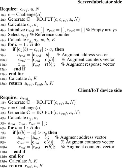
Algorithm 3. Repeated-challenge with bit selection algorithm when applied to a RO PUF.
8 PUF Performance
We illustrate in this section the performance of four types of PUFs when the three authentication algorithms of Section 7 are applied.
The simulations were conducted using MATLAB version R2021b running on an iMAC with 3.8 GHz, 8-core Intel i7 with 64 GB DDR4. Random number generation used the built-in function randn. Simulations for each type of PUF were done for a given value of the response size B. For each value of B a new simulation was performed and the simulations were run 1,024 times to obtain the mean values of the performance figures.
8.1 Static Random Access Memory Physically Unclonable Functions Performance
The performance results of the SRAM PUF are summarized in Table 1 for the three proposed authentication algorithm. We used the following parameter values μp = 1, σp = 0.3, SNRmax = 30 dB, W = 1 K words, N = 1,024 iterations.
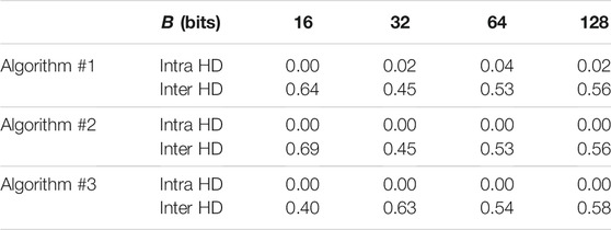
TABLE 1. Normalized intra- and inter-Hamming distances for the SRAM PUF performance.
We notice from the table that Algorithm 1 results in non-zero intra Hamming distance (HD). Therefore error correcting coding is required to remove the noise form the response of the IoT edge device in the field. On the other hand, the intra HD for Algorithm 2 and Algorithm 3 are zero and error correcting coding is not needed.
8.2 Ring Oscillator Physically Unclonable Functions Performance
The performance results for the RO PUF are summarized in Table 2 for the three proposed authentication algorithm. For RO PUF we used the following parameter values S = 3 inverters, μp = 1, σp = 0.3, SNRmax = 30 dB.
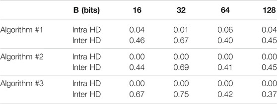
TABLE 2. Normalized intra- and inter-Hamming distances for the RO PUF performance.
The performance of RO PUF in the table indicates that Algorithm 1 requires use of error correcting codes since the intra HD is non-zero. On the other hand, the intra HD for Algorithm 2 and Algorithm 3 are zero and error correcting coding is not needed.
8.3 Arbiter Physically Unclonable Functions Performance
The performance results for the arbiter PUF are summarized in Table 3 for the three proposed authentication algorithm. For arbiter PUF we used the following parameter values S = 15 switching stages, SNR = 30 dB, σp = 0.3, and τsetup = 1.
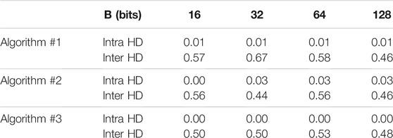
TABLE 3. Normalized intra- and inter-Hamming distances for the arbiter PUF performance.
The performance of Arbiter PUF in the table indicates that Algorithm 1 and Algorithm 2 require use of error correcting codes since the intra HD is non-zero. On the other hand, the intra HD for Algorithm 3 is zero and error correcting coding is not needed.
8.4 Coating Physically Unclonable Functions Performance
The performance results for the coating PUF are summarized in Table 4 for the three proposed authentication algorithm. For coating PUF we used the following parameter values SNR = 30 dB and σp = 0.3.
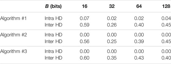
TABLE 4. Normalized intra- and inter-Hamming distances for the coating PUF performance.
The performance of coating PUF in the table indicates that Algorithm 1 requires use of error correcting codes since the intra HD is non-zero. On the other hand, the intra HD for Algorithm 2 and Algorithm 3 are zero and error correcting coding is not needed.
9 Physically Unclonable Functions Types Comparison
We summarize in this section the practicality of implementing the different PUF types from different perspectives. Table 5 summarizes this comparison.
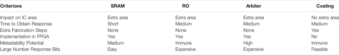
TABLE 5. Comparing the practicality of implementing the different PUF types from different perspectives.
From the table we can conclude that the SRAM PUF presents a good option for PUF implementation.
10 Conclusion
Five different physically unclonable functions were explained: SRAM PUF, RO PUF, arbiter PUF, coating PUF and DRAM PUF as well as their structure and operation. Statistical models for these PUFs were reviewed and the random variable for each PUF was identified. The main system parameters were also discussed in the developed models. Techniques used by the manufacturer to obtain the device CRP data were discussed. This work then reviewed three authentication algorithms to obtain the CRP of four types of PUFs most often used in the field. The performance of the PUFs is presented and it is concluded that the Repeated-Challenge with Bit Selection algorithm gives the best performance since the response bits are noise-free and do not require using the fuzzy extractor algorithm to remove the noise.
Author Contributions
FG did the modeling and simulations. MM did the review and suggested topic.
Conflict of Interest
The authors declare that the research was conducted in the absence of any commercial or financial relationships that could be construed as a potential conflict of interest.
Publisher’s Note
All claims expressed in this article are solely those of the authors and do not necessarily represent those of their affiliated organizations, or those of the publisher, the editors and the reviewers. Any product that may be evaluated in this article, or claim that may be made by its manufacturer, is not guaranteed or endorsed by the publisher.
Acknowledgments
The authors acknowledge the support of the National Research Council (NRC) of Canada under the Collaborative R&D Initiative HQP Grant Application.
References
Alkatheiri, M. S., and Zhuang, Y. (2017). “Towards Fast and Accurate Machine Learning Attacks of Feed-Forward Arbiter PUFs,” in IEEE Conference on Dependable and Secure Computing, Taipei, Taiwan, 7-10 Aug. 2017 (IEEE). doi:10.1109/DESEC.2017.8073845
Delvaux, J., Gu, D., Schellekens, D., and Verbauwhede, I. (2014). Helper Data Algorithms for PUF-Based Key Generation: Overview and Analysis. IEEE Trans. Comput. 34, 889–902.
Delvaux, J. (2017b). Machine Learning Attacks on PolyPUF, OB-PUF, RPUF, and PUF–FSM. IACR Cryptology.
Delvaux, J. (2017a). “Security Analysis of PUF-Based Key Generation and Entity Authentication,”. Ph.D. thesis. Belgium (Europe): University of KU Leuven and ShangHai Jiao Tong University.
Dodis, Y., Ostrovsky, R., Reyzin, L., and Smith, A. (2008). Fuzzy Extractors: How to Generate strong Keys from Biometrics and Other Noisy Data. SIAM J. Comput. 38, 97–139. doi:10.1137/060651380
Dodis, Y., Reyzin, L., and Smith, A. (2004). “Fuzzy Extractors: How to Generate strong Keys from Biometrics and Other Noisy Data,” in Advances in Cryptology – EUROCRYPT Volume 3027 of Lecture Notes in Computer Science. Editors C. Cachin, and J. L. Camenisch, 523–540. doi:10.1007/978-3-540-24676-3_31
Ebrahimabadi, M., Younis, M., Lalouani, W., and Karimi, N. (2021). “A Novel Modeling-Attack Resilient Arbiter-PUF Design,” in 34th International Conference on VLSI Design and 2021 20th International Conference on Embedded Systems (VLSID), Guwahati, India, 20-24 Feb. 2021 (IEEE). doi:10.1109/vlsid51830.2021.00026
Fakroon, M., Alshahrani, M., Gebali, F., and Traorè, I. (2020). Secure Remote Anonymous User Authentication Scheme for Smart home Environment. Internet Things 9, 100–158. doi:10.1016/j.iot.2020.100158
Fakroon, M., Gebali, F., and Mamun, M. (2021). Multifactor Authentication Scheme Using Physically Unclonable Functions. Internet Things 9, 1–28. doi:10.1016/j.iot.2020.100343
Garcia-Bosque, M., Diez-Senorans, G., Sanchez-Azqueta, C., and Celma, S. (2020). Proposal and Analysis of a Novel Class of PUFs Based on Galois Ring Oscillators. IEEE Access 8, 157830–157839. doi:10.1109/access.2020.3020020
Gassend, B., Clarke, D., Dijk, M. V., and Devadas, S. (2002). “Silicon Physical Random Functions,” in Proceedings of the 9th ACM Conference on Computer and Communications Security, Washington, DC USA, November 18 - 22, 2002 (Washington, DC: Association for Computing Machinery), 148–160. doi:10.1145/586110.586132
Hashemian, M. S., Singh, B., Wolff, F., Weyer, D., Clay, S., and Papachristou, C. (2015). “A Robust Authentication Methodology Using Physically Unclonable Functions in DRAM Arrays,” in 2015 Design, Automation & Test in Europe Conference & Exhibition (DATE), Grenoble, France, 9-13 March 2015 (IEEE), 647–652. doi:10.7873/DATE.2015.0308
He, Z., Chen, W., Zhang, L., Chi, G., Gao, Q., and Harn, L. (2020). A Highly Reliable Arbiter PUF with Improved Uniqueness in FPGA Implementation Using Bit-Self-Test. IEEE Access 8, 181751. doi:10.1109/access.2020.3028514
Honsberg, C. (2021). Effect of Temperature. Available at: https://www.pveducation.org/pvcdrom/solar-cell-operation/effect-of-temperature.
Jahn, S., and Borrás, J. C. (2007). Qucs: A Tutorial Getting Started with Qucs. Available at: http://qucs.sourceforge.net/docs/tutorial/getstarted.pdf
Keller, C., Gürkaynak, F., Kaeslin, H., and Felber, N. (2014). “Dynamic Memory-Based Physically Unclonable Function for the Generation of Unique Identifiers and True Random Numbers,” in 2014 IEEE International Symposium on Circuits and Systems, Melbourne, VIC, Australia, 1-5 June 2014 (IEEE), 2740–2743. doi:10.1109/ISCAS.2014.6865740
Machida, T., Yamamoto, D., Iwamoto, M., and Sakiyama, K. (2015). A New Arbiter PUF for Enhancing Unpredictability on FPGA. The Scientific World Journal.
Maes, R. (2013). Physically Unclonable Functions: Constructions, Properties and Applications. Springer.
Maes, R., van Herrewege, A., and Verbauwhede, I. (2012). “PUFKY: A Fully Functional PUF-Based Cryptographic Key Generator,”. Cryptographic Hardware and Embedded Systems (CHES) (Springer). doi:10.1007/978-3-642-33027-8_18
Maes, R., Tuyls, P., and Verbauwhede, I. (2009). “Low-Overhead Implementation of a Soft Decision Helper Data Algorithm for SRAM PUFs,”. Cryptographic Hardware and Embedded Systems (CHES). Editors C. Clavier, and K. Gaj (Springer), 332–347. doi:10.1007/978-3-642-04138-9_24
Sutar, S., Raha, A., and Raghunathan, V. (2016). “D-PUF,” in 2016 International Conference on Compliers, Architectures, and Sythesis of Embedded Systems (CASES), Pittsburgh, PA, USA, 2-7 Oct. 2016 (IEEE), 1–10. doi:10.1145/2968455.2968519
Sutar, S., Raha, A., and Raghunathan, V. (2018). Memory-based Combination Pufs for Device Authentication in Embedded Systems. IEEE Trans. Multi-scale Comp. Syst. 4, 793–810. doi:10.1109/TMSCS.2018.2885758
Tang, Q., Zhou, C., Choi, W., Kang, G., Park, J., Parhi, K. K., et al. (2017). “A DRAM Based Physical Unclonable Function Capable of Generating >1032 Challenge Response Pairs Per 1Kbit Array for Secure Chip Authentication,” in 2017 IEEE Custom Integrated Circuits Conference (CICC), Austin, TX, USA, 30 April-3 May 2017 (IEEE), 1–4. doi:10.1109/CICC.2017.7993610
Tang, Y., Wu, D., Cao, Y., and Margraf, M. (2020). “The Shift PUF: Technique for Squaring the Machine Learning Complexity of Arbiter-Based Pufs: Work-In-Progress,” in International Conference on Compilers, Architecture, and Synthesis for Embedded Systems (CASES), Shanghai, China, 20-25 Sept. 2020 (IEEE). doi:10.1109/cases51649.2020.9243781
Tuyls, P., Schrijen, G.-J., Škorić, B., van Geloven, J., Verhaegh, N., and Wolters, R. (2006). “Read-proof Hardware from Protective Coatings,” in Cryptographic Hardware and Embedded Systems - CHES 2006 Ser. Lecture Notes in Computer Science (Springer), 4249, 369–383. doi:10.1007/11894063_29
Keywords: IoT authentication, SRAM PUF, ring oscillator PUF, RO PUF, arbiter PUF, coating PUF, DRAM PUF, PUF modeling
Citation: Gebali F and Mamun M (2022) Review of Physically Unclonable Functions (PUFs): Structures, Models, and Algorithms. Front. Sens. 2:751748. doi: 10.3389/fsens.2021.751748
Received: 01 August 2021; Accepted: 01 November 2021;
Published: 11 January 2022.
Edited by:
Prosanta Gope, The University of Sheffield, United KingdomCopyright © 2022 Fayez Gebali and Her Majesty the Queen in Right of Canada, as represented by National Research Council of Canada for the contribution of Mohammad Mamun. This is an open-access article distributed under the terms of the Creative Commons Attribution License (CC BY). The use, distribution or reproduction in other forums is permitted, provided the original author(s) and the copyright owner(s) are credited and that the original publication in this journal is cited, in accordance with accepted academic practice. No use, distribution or reproduction is permitted which does not comply with these terms.
*Correspondence: Fayez Gebali, fayez@uvic.ca