CHES robotic observation software kit
 Chen Zhang1,2*
  Can Zhu2
- 1University of Science and Technology of China, Hefei, Anhui, China
- 2Purple Mountain Observatory, CAS, Nanjing, China
CHES (changing event survey) is an optical survey program that not only aims at searching fast-moving RSOs in the sky for space domain awareness but also takes other scientific goals into account, such as NEO and transient events. After the success of the first array located at the Yaoan site in China, it evolved into a wider network consisting of various types of devices. This study presents a full-function framework for coordinating observation across such a network. The robotic observation system takes both extension flexibility and operation simplicity into account to meet special requirements such as timing, complex tracking, dynamic scheduling, unique device configuration, and distributed collaborative observation. Currently, this Python-based system has been deployed to several sites, supporting observation systems from single, entry-level telescopes to multiple medium-sized professional telescopes and performing predefined routing surveys and user-defined observation for different scientific goals. Some of them run unattended for a regular survey to maintain the base catalog and produce survey images for different purposes.
Introduction
Telescope networks and robotic techniques
Astronomy is an observation driven subject oriented by new discoveries. Telescope networks can play important roles in many aspects of this subject, from high energy astrophysics to planetary science. As the development of telescope and detector technology, especially technics related to the robotic observation, more and more networks have been created to meet various scientific goals.
The International Scientific Optical Network (ISON) (Molotov et al., 2008) from KIAM is a very successful global optical telescope network with more than 30 telescopes at more than 20 sites which focus on near-Earth asteroids, space debris, and gamma-ray burst. KDS Polaris is its integrated telescope control system (TCS) written in C# for high-performance, fully automated observation within the framework of the survey program for searching small bodies in the solar system, observation for target designation (both asteroids and comets and space debris in the Earth orbit), as well as for alert (urgent) observation of short-lived optical transients, such as optical components of gamma-ray bursts afterglow. In addition, another Python-based distributed client–server architecture TCS Forte (Kouprianov and Molotov, 2017) is developed to enable extreme flexibility and scalability to a wide range of sensor apertures and configurations. The Burst Observer and Optical Transient Exploring System (BOOTES) (Castro-Tirado et al., 1998) from IAA is a network of 60-cm telescopes to quickly observe transient events within seconds or minutes of being detected by scientific satellites. Its networked robotic driving system is the well-known Remote Telescope System, 2nd version (RTS2) (Kubánek et al., 2004), which is composed of several device servers, central server, and various observational clients that cooperate over a TCP network. Also, BOOTES has a remotely accessible system whose TCS is based on ASCOM under Windows for device compatibility. Télescope à Action Rapide pour les Objets Transitoires (TAROT) is an optical network for GRB (Boër et al., 1996) and RSO observation (Boër et al., 2017). The developed control software ROS (Klotz et al., 2008) is a set of programs connected by a web interface. The Gravitational-wave Optical Transient Observer (GOTO) (Dyer et al., 2020) is a wide-field telescope network that focuses on detecting optical counterparts to gravitational-wave sources, which consists of multiple telescope units with a shared robotic mount. The GOTO Telescope Control System (G-TeCS) (Dyer et al., 2018) comprises of multiple independent Python-based control daemons and a “just-in-time” scheduler, which are supervised by a master control program. The Arizona Robotic Telescope Network (ARTN) (Weiner et al., 2018) project is a flexible 1- to 3-m class telescopes network to carry out monitoring, rapid responding, and transient/target-of-opportunity following-up in various domain of astronomy. The project creates an INDI-based TCS-NG (TCS Next Generation) along with AzCam to support RTS2 working as a control system. The Stellar Observations Network Group (SONG) (Grundahl et al., 2008) is a global network of 1-m telescopes to be able to observe single objects continuously for days, weeks, and even months. The overall system is operated by a database-driven control system, which consists of several Python software packages (Andersen et al., 2019). The Las Cumbres Observatory (LCO) (Brown et al., 2013) is a private operating network of astronomical observatories mainly for time domain astronomy. Its robotic control system (RCS) (Fraser and Steele, 2004) works along with the telescope control system (TCS) and the instrument control system (ICS). The Search for habitable Planets EClipsing ULtra-cOOl Stars (SPECULOOS) (Delrez et al., 2018) project keeps a close eye on terrestrial planets hunting around nearby cool dwarfs. It uses the commercial observation system DC-3 Dreams® ACP. The Test-Bed Telescopes (TBT) project (Ocaña et al., 2016) works as a prototype of the autonomous optical observing system for future NEO and space situational awareness networks. RTS2 works as its TCS and specialized planning and scheduling softwares (Racero et al., 2015) are adapted to RTS2 to work together.
CHES program requirements and existing techniques
Changing event survey (CHES) (Chen and Changyin, 2021) is a general optical survey program mainly aimed at cataloging and discovering Earth orbital resident space objects (RSOs), but it also follows the interests of other astronomical goals. It is carried out by multiple small- to medium-sized wide-field optical telescopes and some other auxiliary telescopes, which form a complex observation network located at multiple sites.
Basically, each sensor unit is a standard astronomical telescope, but to meet the requirements of RSO observation, there are some special features, including the following:
• GPS timing latch for frame high-precision timestamping;
• tracking with a custom rate and a variable rate other than the sidereal rate;
• support special telescope configuration, such as multi-instruments, multi-channels, and collaborative telescope array;
• dynamic observation coordination;
• on-site plan adjustment from real-time observation feedback;
• multi-user and multi-goal observation robotic coordination.
These requirements are ultimately manifested in not only telescope hardware and software but also the upstream coordination system. Because of the development of instruments techniques and the difference in operating conditions, the network contains many kinds of telescopes, and the observation requirements may expand as new types of devices are used. Therefore, the system should be flexible and scalable to face the variety of devices, drivers, software environments, and observation requirements.
The core component of this kit is the telescope control system (TCS), shown in Figure 1. It connects devices, interprets observation requests, and carries out actions. To support different hardware configurations within a uniform operating framework, the device-specific code and general function code should be separated properly; the common practice is wrapping each device’s code into a standard API.
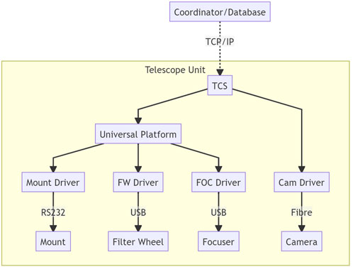
FIGURE 1. ogical connection of TCS. It communicates with upstream modules such as observation coordinator and operation databases and connects all devices within each telescope unit. Typical devices including mount, filter wheel, and focuser are connected via a universal platform, which can supply a standard API, but also some devices such as camera can be connected directly due to the performance requirements.
There are many TCS solutions, from open source Ekos; to proprietary Software Bisque® TheSkyX, Cyanogen Imaging® MaxIM DL, and DC-3 Dreams® ACP; professional systems such as OCS (Hickson, 2019) used by ES-MCAT; and systems mentioned before such as RTS2 and FORTE. These open and commercial systems usually could perform scheduled observation sequentially and have been widely used in astronomical photography and small observation projects. However, there are some limitations if we want to apply them to the CHES program, such as missing the networking, rate tracking, or timing function. Because of this reason, we decided to develop a whole system for CHES robotic operation as other professional systems do.
A universal device platform provides a consistent API for the same type of devices, which helps to reduce the compatibility code within TCS for various devices support. Currently, in open source community there are several universal platforms that have broad compatibility, such as ASCOM/ASCOM Alpaca and Indi/Indigo. Also, RTS2 has its own universal platform. ASCOM is called a de facto standard for amateur to entry-level professional telescope, which provides a universal API for different types of telescope mounts, cameras, auxiliary devices, and even useful telescope control functions. To add cross-platform capability, the ASCOM team published a new platform called ASCOM Alpaca. ASCOM Alpaca uses restful technology to implement a web-based API other than the traditional ASCOM’s Microsoft® COM. After years of development, there are plenty of support from manufacturers and software clients. Indi and its fork Indigo are a cross-platform distributed telescope framework, which uses XML-based C/S architecture. They are more welcomed in the open source community under the POSIX system and support many embedded systems such as Arduino. In addition, there is a Windows Indi server to bridge the ASCOM API. RTS2’s bridge is not a standalone platform. It supports Indi API, but in most cases it uses independently developed drivers for performance. Limited by the developing community, the device support capability is insufficient, and many supported devices are old model.
Each device has its own driver, and a driver wrapper if it supports other platforms. Usually, this is enough to adapt to the TCS, but because of the compatibility consideration, this solution may lack performance and some functions, especially noticeable in the camera driver. The image data throughput of modern high-resolution high frame rate CMOS is far beyond the capability of a universal platform, also the rich settings. So, in some cases, a customized driver directly from device SDK is preferable.
Hardware systems
Currently, the CHES observation system has been used on multiple sets of telescopes at multiple sites, which involves different types of instruments.
• The first CHES array is located at Yaoan. It consists of 12 280-mm refractor, shown in Figure 2, and two 800-mm reflector and comprises an ASA DDM85P equatorial mount, FLI PL09000 CCD camera, ASA AZ800 altazimuth telescope, and Andor iKon XL 231 CCD camera;
• the Dragonfly telescope network is located at Lenghu, Muztagh, and Samoa; each site has one 280-mm refractor and one 400-mm reflector and comprises an ASA DDM100 equatorial mount and a FLI KL4040 CMOS camera;
• 400-mm reflector at Ali uses a 10 micron GM1000HPS equatorial mount and a FLI ML50100 CCD camera;
• 200-mm reflector at Xuyi uses a Paramount MX equatorial mount and a QHY600P CMOS camera.
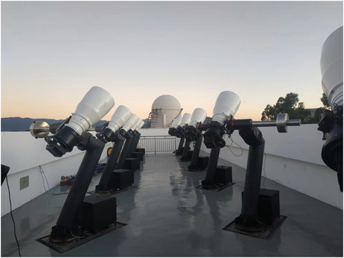
FIGURE 2. Photo of the CHES-YA telescope array located at the Yaoan site which consists of 12280-mm refractor under a rolling roof.
All these sites are connected to the Nanjing center for universal coordination.
Observation system design
System architecture
The dedicated observation system for a certain project or facility has different design patterns. The all-in-one (AIO) system integrates all functions into an integral software program works as a black box with plan input and data output, usually be developed for a fixed model facility that has fixed functionality. The do-one-thing (DOT) system follows the philosophy of do one thing and do it well from unix community, consists of a bunch of programs and uses scripts to call these programs sequentially to finish a job, and usually works with research-grade facility. The AIO system has consistent usage experience, but it lacks flexibility and robustness. It is difficult to extend the observation mode and needs intensive maintenance to ensure the availability of all mutually influenced parts. The DOT system is flexible enough, can meet almost any needs with extraordinary design, and has lower development cost by introducing massive community resources. The problem is the user experience and maintenance difficulty.
The CHES survey system takes both ideas into account by using a multilevel scheme. The software architecture is designed as several layers, center, site, sensor group, and single sensor. The basis of this distinction is the operations’ mutual dependency within each layer and the decoupling between layers. Each layer has a single program to deal with the internal logic, and they work together via communication. Some failure may only cause functional loss other than crash the whole system, and it can be replaced easily. For example, if the weather monitor in the site layer fails, the robotic operation will be damaged. But we can replace the monitor with a simple time-related logic temporarily if we are sure about the weather until we put the weather monitor back online. This could keep the system operational capability as much as possible. The center layer works as a data hub and user interface, which involves observation requests, working status, and final data products. The site layer provides support for observation such as operating conditions and environment monitoring. Sensor groups and single sensors are the actual operators, and the difference is about telescope arrays. The sensor group program can perform joint observation by controlling several telescopes to work together. Inside each program, procedures follow a strict logic and work as an entirety; the communication between programs uses a file system, database, or WebSocket depending on the timeliness requirements. The overall system architecture is shown in Figure 3.
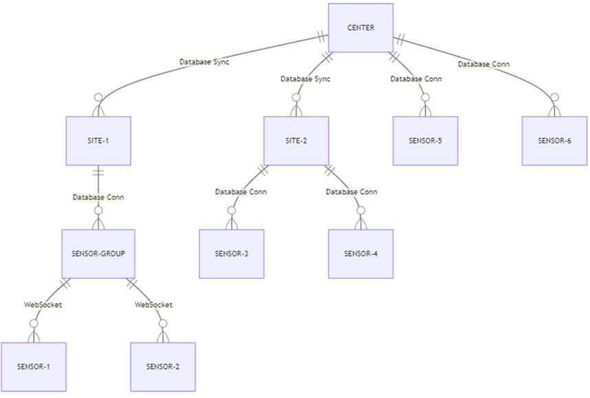
FIGURE 3. CHES optical telescope network architecture. Sensor is a minimum single telescope unit which can be work independently; sensor group is a bunch of sensors which logically work as an entirety in the same site; site means all sensors in a geographical observatory that share one CHES supporting facility, such as weather and on-site data center; center is a logical data center which aggregate all the sensors’ I/O together, either locates in PMO or its redundant backup center.
Data model and work flow
Under full-function operation, the data center receives generally described observation requests from upstream calculations and user indications. These requests will be translated into specific observation plans that can guide certain sensors and then be distributed to these sensors. When the plan is acquired by the sensor, the sensor will ask the site for assistant information to decide whether to perform. Finally, the sensor program controls the telescope to carry out actual actions. Because of the need of real-time feedback, there is an on-site data reduction facility to reduce raw images, and the reduced product is fed back to the system as well as the center database. The overall workflow is shown in Figure 4.
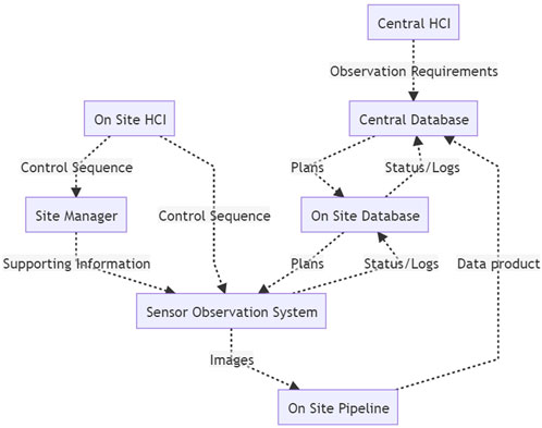
FIGURE 4. CHES network system connection and data flow. Each part runs a set of closely connected programs from this software kit and work together by exchanging different types of information.
Most non-real-time data communication is performed via database systems, such as plans, data products, operation logs, system status, and environmental information. DBS provides data consistent communication for multiple clients synchronization, data permanence, and rich query capability. Under the circumstance of a poor internet connection, a loosely bidirectional database synchronization mechanism is implemented with a restful server at the center.
In addition, there are some other real-time communication needs, such as device manual operation and massive communication for HCI whose data do not need to be retained. These will be done using WebSocket communication. The WebSocket protocol can be used easily in web environments.
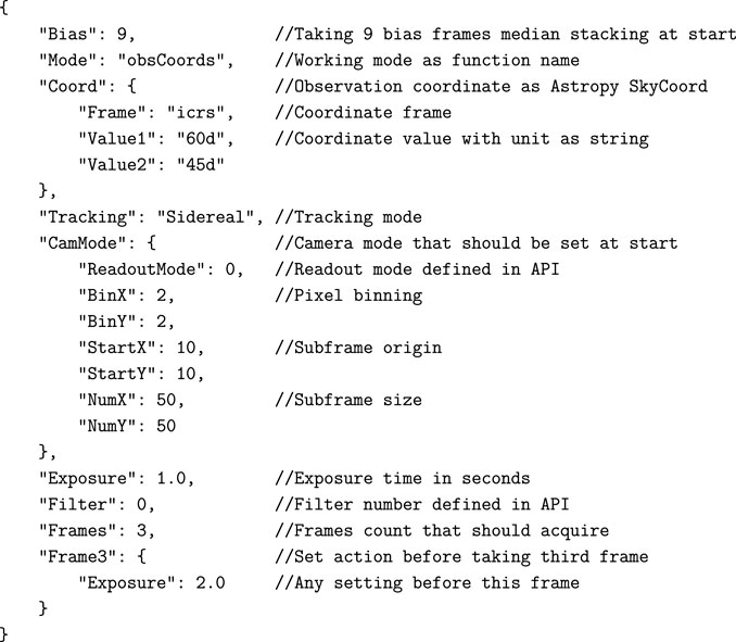
The computation, storage, and transmission throughput of modern computer systems are high enough to let us choose flexible formats other than formatted or binary data structures. Here, we use JSON as the primary information exchange format among different parts of this software kit, such as control sequence and state quantity. JSON is simple, human-readable, flexible, scalable, and perfectly matches the dict type of system language Python. We have defined JSON keys for observation plans, device operations, and site conditions to fulfill the fine-tuning of each observation.
A sample JSON plan is shown in Appendix 1. This is the observation guidance part of a plan directly related to the telescope control; the other parts for plan query are presented in other column of the plan database. According to this plan, the TCS will get device prepared such as bias and dark calibration frame acquisition, switch filter, and set up camera parameters. Then move the telescope and take exposures. Most of the information in this plan is action parameters. We used SkyCoord from astropy.coordinates (Astropy Collaboration et al., 2018) other than the values in the special coordinate frame for flexibility; no matter what coordinate the telescope used, the device code will transform the coordinate to the right one. Following the ASCOM convention, in a common scenario, the coordinates will be transformed to true equator true equinox (TETE) when sidereal tracking need to be activated immediately after slewing and altitude–azimuth (AltAz) when we want the telescope to keep still after slewing. The coordinate frame is prepared based on the site location and time in advance. The camera control is the most complicated part if we want to achieve the best performance under various scenarios. The JSON format is suitable to extend parameters keywords. Other than the common readout mode, binning, subframe, offset, and gain, we can have more such as the CMOS merge mode, USB traffic, DDR buffer, and even FITS (Wells et al., 1981) header keywords setting. The action can be guided according to the presence of these optional parameters. Moreover, the parameters can be repeated to adjust the behavior of a certain frame, to observe a series of coordinates or with a series of filters.
Data archive
The main data product of CHES program is images. The format of image data is FITS supported by the astropy package, including tile compression for bandwidth saving and multi-extension for exposure grouping. The ASDF (Greenfield et al., 2015) format is another supported modern choice, and the image saving–related code is isolated to support various formats.
Typically, one sensor can produce 200–1000 GB raw images per night depending on the camera resolution, because of the short exposure. Images will be sent to the on-site storage for reduction while being cached in an acquisition computer for a couple of days. Raw images of short exposure are cached in on-site storage after reduction for several months. Stacked, ROI, and other scientific images are tile compressed, archived, and sent to data center for permanent retention via Internet, tape, or disc. This reduces each sensor’s image archive size to tens of gigabytes per night. The raw images can be accessed internally for backtracking during the caching period, whereas the archived images can be accessed publicly from data center.
Observation system
Programming language
Programming technology affects the implementation. Thanks to the high performance and broad compatibility, static languages such as C++ or C# are used when hardware and massive calculation are involved. Meanwhile, dynamic languages can provide more flexibility and scalability when dealing with the control pipe logics. Python community has extraordinary base in machine learning, scientific computing, hardware controlling, and even web hosting. This made us to choose Python as the main programming language of TCS, site manager, web interface, and other auxiliary programs. It is also a good choice to glue all static language drivers together even by Cython coding when performance is required.
TCS and observation program
To adapt different working environments and telescope configurations, this program is designed as cross-platform and multithreaded. The program has the following features:
• direct access to all hardware devices, including mount, focuser, filter wheel, rotator, timing, and so on;
• translate the plan into device actions and operate properly;
• feedback system overall status, especially device status during operation;
• query plan with predefined strategy which may differ for each telescope;
• auxiliary features, such as configuration, logging, HCI, WebSocket communication, and database access.
This program has several modules to accomplish the observation goal and the relations among them, as shown in Figure 5. During the whole life cycle of a running instance, there are four threads that keep working, to deal with GUI responding, websocket communication, telescope controlling, and operation management. The practical operation related to a specific plan is performed by an independent operation thread which can choose different modules according to the plan indication, such as observing a series of coordinates or tracking a moving object. Currently, the operation module collection includes coordinates observation and orbital tracking observation and can be extended via a program plug-ins mechanism in the future. The decision of which plan to perform is made by Plan Manager according to the information in the plan database. Basically, all the modules communicate with the central management thread.
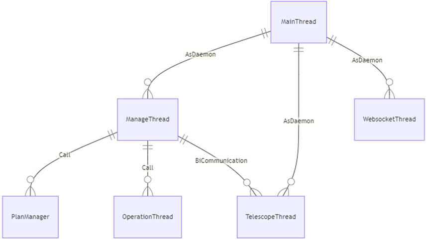
FIGURE 5. Modules and relations among them within the TCS program structure. MainThread, ManageThread, WebsocketThread, and TelescopeThread are long-lived daemon thread to maintain the system operation. The extensible OperationThread performs the observation plan and PlanManager provide plan acquisition strategy.
Telescope control
To support different devices, the usual method is to abstract each type of device driver and encapsulate it into a common API, such as ASCOM or Indi. If it is impossible to use all devices with ASCOM or Indi platform, then the driver must be encapsulated again. For most cases, this would be a duplicated work; and if there is no common API for some special devices, the code base could be messier. In this system, we decide to abstract the device code from another perspective that encapsulates several actions into a common operation, such as slew, set rate, take image, or even startup and shutdown. This can still use ASCOM or Indi platform, if available, to reduce the development complexity. Each operation involves multiple devices, so they work together more closely and have many more possibilities. In addition, we can add system features related to the telescope, such as preparing a standard FITS header for data reduction and managing the remaining disk space. For CHES project currently used devices, we implement a device configuration based on ASCOM drivers and a customized timing tag device. However, because of the particularity of Ascom 2X Mount Adaptor’s offset tracking rate used by the Paramount mount, we have another telescope configuration using TheSkyX RASCOM.
Image acquisition
Using a device from Python via ASCOM is very convenient, but there is a performance issue when reading a camera. ASCOM uses Microsoft COM technology and stores image data in SAFEARRAY. When converting a very large image from a SAFEARRAYto a NumPy array, it takes a very long time because of the loop used. A safearray_as_ndarray decorator from the comtypes module can improve slightly but not sufficiently when handling the modern large format CMOS. Therefore, we develop two Python modules, python-qhy and python-fli, with ASCOM compatible APIs to support the QHYCCD® and FLI® cameras. The module is written in Cython language to call the native SDK on Windows and Linux. The code can operate the camera as fast as the SDK original speed. The module has both official API and ASCOM API to use under different circumstances.
When observing RSO, the time accuracy should be higher than micro seconds. The operation of the camera is controlled by internal logics, so a high precision time tagging system is used. One method is to use a GPS PPS signal to trigger the camera externally, and the other is to trigger the time latch by using the frame exposure indicator signal from the camera. The timestamp tagging procedure can be performed by using the camera internal system or read from a serial port. This system supports either way.
Coordinate system and tracking
The coordinate system used by the telescope includes topocentric equatorial, J2000 equatorial, and altitude–azimuth coordinates. Thanks to the astropy.coordinates module, the system supports different coordinate inputs and transforms them to required coordinates. The topocentric frame is equivalent to the TETE frame from Astropy.
When tracking RSOs, the telescope moves nonsidereally. Usually telescopes support offset tracking and/or axis movement. Offset tracking is more precise, as the axis rate is calculated with pointing model, but the axis movement can be faster in some of mounts’ software. This system supports both methods and chooses offset tracking preferentially. When performing rate tracking, the average rate from position difference is recommended rather than the instantaneous rate. This is to keep the telescope axis rate fixed during the exposure, to ensure that the center of the star streak is related to the middle of the exposure time.
Observation method
The designed survey types include sky field surveys, solar body surveys, and Earth orbital surveys. The major difference is the tracking rate because latter’s tracking rate is time-varying. Each observation mode is implemented as an individual derived class of threading.Thread and works as a plug-in to the main program. This means we can extend the observation mode later without modifying the main program. Each time it starts a new plan, a new observation thread instance is started until the plan is completed or aborted, so the actual observation night is divided into multiple observation units. The observation thread and daemon thread can access the devices at the same time.
Sky field observation involves taking several images at specific coordinates with specific rate sequentially. First, all parameters in the plan are set, including exposure time, camera parameters, and filter, and then calibration frames are taken with set camera mode if necessary. The second step is slewing the telescope to the coordinates and setting the tracking rate. After that, the frames are exposed. It is worth mentioning that the system can perform all set procedures before a specific frame so that the plan is flexible enough for most cases.
For NEO or RSO observation, the tracking rate is strictly time-related. To maximize the detection depth, we should set the rate before each frame. We do not implement it with frame lists only like the sky field survey mode. Instead, we use instance-guided open loop tracking with a custom coordinate generator, such as TLE propagator, Ephem propagator, or ephemeris table lookup generator. The procedure is shown in Figure 6. Similar to sky field observation, first, the telescope should go to the coordinate at 20 s later and check the remaining time until there is still some time left. After that, count down and start to move the telescope by using the axis rate control.
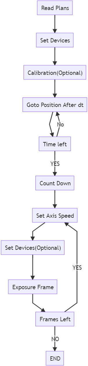
FIGURE 6. Open loop orbital object tracking observation workflow. This is key to observing very faint fast-moving object, to make sure the signal accumulate correctly. Due to the strong correlation of time and position, the workflow is time sensitive.
A plan defines a set of actions with sequential logic, and it is irrelevant between plans. The life cycle of a plan is shown in Figure 7. Therefore, there is no need to make a strict sequence for plans; instead, the observation resource can be maximized by dynamically adjusting oversaturated plans. The possible conflict of plans requires an instant scheduler. In each plan record, in addition to the guidance data, there are also metadata to help the decision system in the scheduler. Metadata includes user-defined priority, valid period, usage timespan, requested fields, objective, and list of demanding sensors. The scheduler will query the plan database and use this metadata to decide which one to start or even abort the running one. With this strategy, all 12 CHES wide-field telescopes can be used as one telescope.
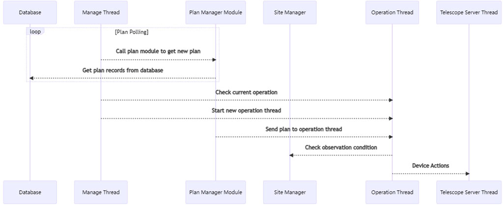
FIGURE 7. Observation plan life cycle. This shows a plan how to be acquired, performed, and which modules are involved, after the plan is inserted to the plan database by user. In addition to the modules in TCS, the site manager is involved to provide the observation condition related to the plan, such as the partial sky field weather condition that plan requests. The observation steps are from top to bottom in order.
There is an all sky field grid map for each telescope according to the field of view, which is recorded in an individual database table. Other than arbitrary coordinates the system can also observe with a predefined sky field serial number. It is good for sky template reduction during the image differential. Any visit of these sky fields will be recorded so that the system can determine which field needs to be visited if the system is free. This helps the system to perform a blind all sky survey while accomplishing other requests.
We define several run levels to support the robotic operation, and daemon thread operates according to the run level. The run level will be assigned by operators, and there are two procedures related to the switch of run level, startup, and shutdown. The shutdown procedure will park the telescope, turn off the camera cooling, switch filter to protector (an aluminum sheet in filter wheel to protect CMOS camera without shutter), turn off mount motor, and turn off mirror shutter, if they are available. The startup procedure will operate in reserve, take the master bias frame, wait for the cooling temperature, and manage the remaining disk space by deleting the outdated file directory.
• −1: System uninitialized;
• 0: Stopped, if switched from other levels, all operations will be aborted, and then shutdown procedure will be performed;
• 1: Paused, keep the telescope standby, started but do nothing;
• 2: Manual, accept operating instruction from GUI and Websocket server, to prevent the conflict between robotic operation and manual operation;
• 4: Guided, operate telescope totally according to the plans, usually for system debugging;
• 5: Robotic, the system will read plans, site condition, and calculate Sun elevation to decide the operation according to the robotic strategy.
Database and interface
The whole system relies on a database system and uses JSON as the primary data exchange format. Therefore, PostgreSQL is the first choice because of its good support of JSON type. Considering the various conditions, the system uses object–relational mapping (ORM) technology from the SQLAlchemy package so that it is easy to turn to other database systems. Similar to the SQLite in the Ali 400 telescope case. The databases between the center and sites are synchronized in some way but are not fully synchronized. Therefore, the synchronization bridge must be customized. The current solution is starting a Restful server at the center, and each site accesses this server to retrieve and post necessary updates.
In some cases, the human–computer interaction (HCI) is still needed, such as system maintenance or single node operation, especially when the operator wants to check the large image interactively. We implement optional user interface (UI) from command line to graphic and web interface by cmd. CUI PySimpleGUI and WebSockets.
For end users and operators who want to access multiple telescopes, site managers and databases at the same place, aggregated web pages are very practical. Users need just a browser to accomplish it. As mentioned before, Python is powerful enough in multiple areas including serving the web. We choose Django from several famous frameworks. It has many apps to make the development easier. This web page primarily serves telescope checking and basic controlling, site environment reviewing, power and dome controlling, and plans adding viewing and modifying.
Site support system
Site management plays an important role in robotic observation. In addition the common features such as manual device control and environment monitor, it can consolidate all information to make decision of observability. The manager should access different kinds of devices, such as.
• APC remote power distribution unit, to control the power supply of each device;
• Boltwood Cloud Sensor and Davis Weather Station, to collect the temperature, wind and cloud metrics;
• All Sky Monitor to record visible sky image;
• SQM sky quality meter to measure the brightness of the night sky;
• Cyclope seeing monitor to measure the seeing;
• Solar power monitor, to retrieve the status of panel and battery;
• Webcams.
Site manager access these devices via ASCOM, serial port, TCP/IP socket, SNMP and other methods. Each type of device is operated in individual thread to gather the information then converge to main thread. The architecture is shown in Figure 8. An analytic thread reduces these data by simple threshold and machine learning to do the decision, then feedback the observability as ASCOM Alpaca SafetyMonitor. Clients can use Restful links or COM object to get the value. Also, the reduced data will be downsized and recorded to the database.
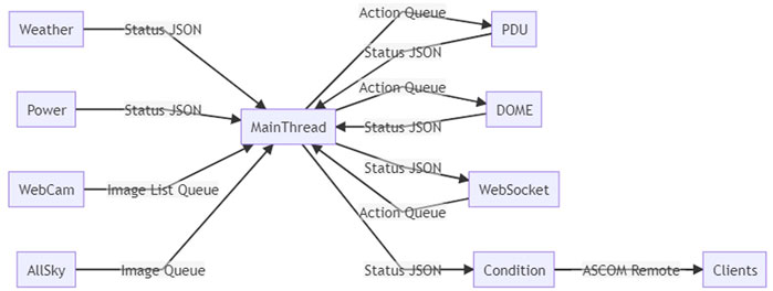
FIGURE 8. CHES site manager architecture. The main thread starts the other threads. Each one is responsible for one function, such as weather monitor device reading, dome controlling, and remote request answering. All the function are coded into the separated thread class so that it can be easily modified, extended or replaced to adapt different scenarios which usually do not have common platform API.
This manager is also a terminal. There is a PySimpleGUI powered GUI and a WebSockets powered server. This websocket server will interact with the web page’s websocket client, so that all features can be available on the website. The GUI of the manager shown in Figure 9.
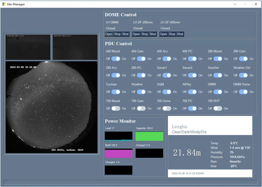
FIGURE 9. CHES site manager UI was used to show the webcam, all sky cam, solar power and weather, and to control the dome and power distribution unit. Each part of this UI is shown only if the related device is presented in the configuration, to keep the code universal for different site as much as possible. The similar UI is implemented in the Django website and communicate with this manager via websocket.
Summary
Current status
Currently, this software has worked routinely on several sensors, including:
• CHES-YA telescope array at the Yaoan site;
• CHES-SA at the Bonnie Vale site;
• CHES-ES with a collaborative Celestron RASA 11 at the El Sauce site;
• Dragonfly-LH, Dragonfly-MF, and Dragonfly-TU at Lenghu Muztagata and Tuamasaga sites separately;
• CANDLE-XY at the Xuyi site;
• CANDLE-AL at the Ngari site.
These telescopes share the same data center for unified coordination and data aggregation.
A GEO region survey, such as in Figure 10, will be carried out three times per night routinely, acquiring thousands of higher orbital tracklets belonging to hundreds of objects by using one large FoV telescope. Using CHES-YA array, wider field can be covered to get more data of up to more than 2000 objects.
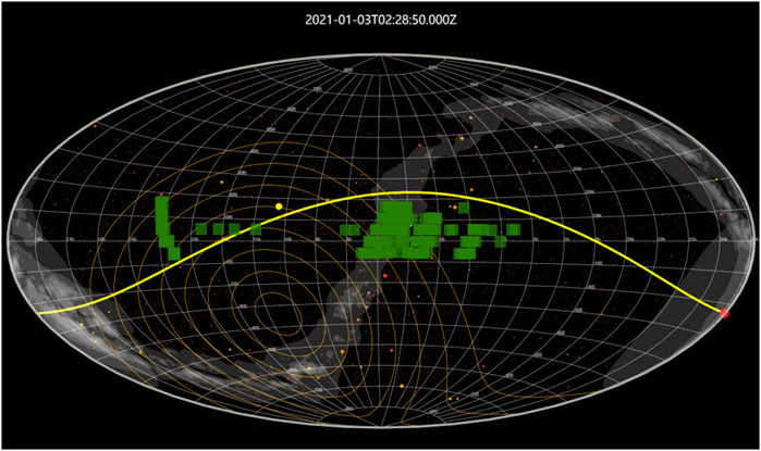
FIGURE 10. A sample survey plan for CHES-SA. The green patches are field of view of the telescope. The observation order is arranged by the movement of twilight terminator and Moon. The survey region is typically five belts around the equator with 6° wide based on the telescope FoV.
During the survey, other objects will be captured too. In the observation of 2020-03-31, CHES-YA got a new bright NEO in the routine survey; the stacked image is shown in Figure 11. It is confirmed as 2020FB7 whose magnitude fell from 11m to 20m in 2 days and then disappeared. The first measurement from CHES-YA is earlier than the public data.
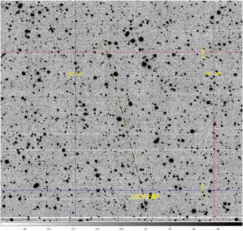
FIGURE 11. The stacked image of 2020FB7 near-Earth asteroid detected by the CHES-YA 280-mm wide field survey. The moving rate is faster than GEO objects and detected as new debris candidate. The following reduction confirmed it as a flyby asteroid.
The system can receive other observation requests and make proper plan for each sensor. For example, a custom plan generator which is triggered by the gamma-ray coordination network (GCN) is implemented to follow important events. The upstream generator produce a searching area based on the event position estimation and a galaxy catalog, as shown in Figure 12. Followed by this procedure, LIGO/Virgo S191216ap (Sun et al., 2019b), GRB 191122A (Sun et al., 2019a), and GRB 190728A events had been followed by CHES-YA for optical counterpart searching.
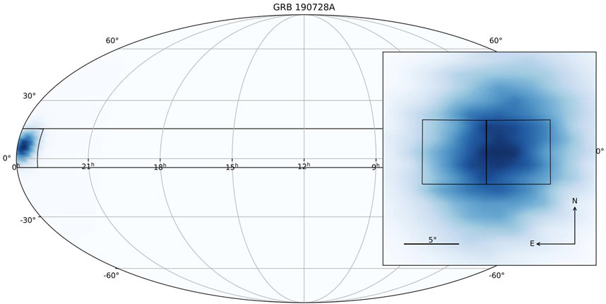
FIGURE 12. This is the searching fields of GRB 190728A event. Based on this, a fast searching plan for this event is carried out by the CHES-YA 280-mm wide field survey.
Another scientific goal of interest is solar bodies’ occultations for faint objects using high-precision positioning. Thanks to the wide distribution of telescopes, there may be greater probability of capturing these events. Several observations have been carried out including Pluto (2020-06-06), Callisto (2020-06-20), Varuna (2020-12-27), and Quaoar (2022-05-17) occultation events.
Conclusion
In this article, the software techniques of a robotic large-field survey network has been discussed in depth, especially the features related to RSO observation and the unified architecture to support various telescope configurations.
The mentioned techniques of software architecture, programming pattern, data model, and network topology are implemented for the CHES-YA telescope array and distributed to other facilities. The system function can satisfy the optical survey needs for RSOs, solar bodies, transient events, and the hybrid coordination of them. Also, currently, the software kit is still in development actively for more telescope support and function such as closed loop tracking and AI observation sequence optimization.
Data availability statement
The raw data supporting the conclusion of this article will be made available by the authors, without undue reservation.
Author contributions
ChZ contributed to conception and design of the software and implemented the local application. CaZ contributed to the user interface design and implemented the web part of the system. ChZ wrote the manuscript. All authors contributed to manuscript revision, read, and approved the submitted version.
Funding
This work was funded by the Basic Research Program of Jiangsu Province, China (Grant No. BK20201510) and the National Natural Science Foundation of China (Grant No. 12073082).
Acknowledgments
The author would like to thank the CHES project team for supporting this development, the technical team for the hardware support, and the staff of Yaoan site for the operation of the CHES telescope array.
Conflict of interest
The authors declare that the research was conducted in the absence of any commercial or financial relationships that could be construed as a potential conflict of interest.
Publisher’s note
All claims expressed in this article are solely those of the authors and do not necessarily represent those of their affiliated organizations, or those of the publisher, the editors, and the reviewers. Any product that may be evaluated in this article, or claim that may be made by its manufacturer, is not guaranteed or endorsed by the publisher.
References
Andersen, M., Grundahl, F., Christensen-Dalsgaard, J., Frandsen, S., Jørgensen, U., Kjeldsen, H., et al. (2019). Hardware and software for a robotic network of telescopes-song. arXiv preprint arXiv:1901.08300.
Boër, M., Atteia, J., Barat, C., Niel, M., Olive, J., Chevalier, C., et al. (1996)., 384. American Institute of Physics, 594–597.The tarot project: An optical glance at grbsAIP Conf. Proc.
Boër, M., Klotz, A., Laugier, R., Richard, P., Pérez, J. C. D., Lapasset, L., et al. (2017). “Tarot: A network for space surveillance and tracking operations,” in 7th European conference on space debris ESA/ESOC.
Brown, T., Baliber, N., Bianco, F., Bowman, M., Burleson, B., Conway, P., et al. (2013). Las cumbres observatory global telescope network, 125. Bristol, England: Publications of the Astronomical Society of the Pacific, 1031.
Castro-Tirado, A. J., Gorosabel, J., Hudec, R., Soldán, J., Bernas, M., Pata, P., et al. (1998). “The status of the burst observer and optical transient exploring system (bootes),” in AIP conference proceedings (American Institute of Physics), 428, 874–878.
Chen, Z., and Changyin, Z. (2021). Activities of pmo optical space debris survey. An. Acad. Bras. Cienc. 93, e20200827. doi:10.1590/0001-3765202120200827
Delrez, L., Gillon, M., Queloz, D., Demory, B.-O., Almleaky, Y., de Wit, J., et al. (2018). “Speculoos: A network of robotic telescopes to hunt for terrestrial planets around the nearest ultracool dwarfs,” in Ground-based and airborne telescopes VII (Bellingham, WA: International Society for Optics and Photonics), 10700, 107001I.
Dyer, M. J., Dhillon, V. S., Littlefair, S., Steeghs, D., Ulaczyk, K., Chote, P., et al. A telescope control and scheduling system for the gravitational-wave optical transient observer (goto). Observatory Operations Strategies, Process. Syst. VII (2018)., 10704. Bellingham, WA: International Society for Optics and Photonics, 107040C.
Dyer, M. J., Steeghs, D., Galloway, D. K., Dhillon, V. S., O’Brien, P., Ramsay, G., et al. (2020). “The gravitational-wave optical transient observer (goto),” in Ground-based and airborne telescopes VIII (Bellingham, WA: International Society for Optics and Photonics), 11445, 114457G.
Fraser, S., and Steele, I. A. (2004). Robotic telescope scheduling: The liverpool telescope experience. Optim. Sci. Return Astronomy through Inf. Technol. 5493, 331–340.
Greenfield, P., Droettboom, M., and Bray, E. (2015). Asdf: A new data format for astronomy. Astronomy Comput. 12, 240–251. doi:10.1016/j.ascom.2015.06.004
Grundahl, F., Christensen-Dalsgaard, J., Kjeldsen, H., Frandsen, S., Arentoft, T., Kjaergaard, P., et al. (2008). Song–stellar observations network group. Proc. Int. Astron. Union 4, 465–466. doi:10.1017/s174392130802351x
Hickson, P. (2019). Ocs : A flexible observatory control system for robotic telescopes with application to detection and characterization of orbital debris.
Klotz, A., Boër, M., Eysseric, J., Damerdji, Y., Laas-Bourez, M., Pollas, C., et al. (2008). Robotic observations of the sky with tarot: 2004–2007, 120. Bristol, England: Publications of the Astronomical Society of the Pacific, 1298.
Kubánek, P., Jelínek, M., Nekola, M., Topinka, M., Štrobl, J., Hudec, R., et al. (2004). “RTS2 - remote telescope system, 2nd version,” in Gamma-ray bursts: 30 Years of discovery. Editors E. Fenimore, and M. Galassi (American Institute of Physics Conference Series), 727, 753–756. doi:10.1063/1.1810951
Molotov, I., Agapov, V., Titenko, V., Khutorovsky, Z., Burtsev, Y., Guseva, I., et al. (2008). International scientific optical network for space debris research. Adv. Space Res. 41, 1022–1028. doi:10.1016/j.asr.2007.04.048
Ocaña, F., Ibarra, A., Racero, E., Montero, Á., Doubek, J., and Ruiz, V. (2016)., 9906. SPIE, 2135–2143.First results of the test-bed telescopes (tbt) project: Cebreros telescope commissioningGround-Based Airborne Telesc. VI. Bellingham, WA.
Astropy Collaboration Price-Whelan, A. M., Sipőcz, B. M., Günther, H. M., Lim, P. L., Crawford, S. M., et al. (2018). The astropy project: Building an open-science project and status of the v2.0 core package. Astron. J. 156, 123. doi:10.3847/1538-3881/aabc4f
Racero, E., Ocana, F., Ponz, D., and TBT, Consortium (2015). Towards an autonomous telescope system: The test-bed telescope project. Highlights Span. Astrophysics 8, 828–833.
Sun, T., Zhang, C., Ping, Y., and Wu, X. (2019a). Grb 191122a: Ches optical observations. GRB Coord. Netw. 26271, 1.
Sun, T., Zhang, C., Ping, Y., and Wu, X. W. (2019b). Ligo/virgo s191216ap: No candidates found in ches observations of hawc error region. GRB Coord. Netw. 26487, 1.
Weiner, B. J., Sand, D., Gabor, P., Johnson, C., Swindell, S., Kubánek, P., et al. (2018)., 10704. International Society for Optics and Photonics, 107042H.Development of the Arizona robotic telescope networkObservatory Operations Strategies, Process. Syst. VII. Bellingham, WA.
Wells, D. C., Greisen, E. W., and Harten, R. H. (1981). Fits - a flexible image transport system. Astronomy Astrophysics Suppl. 44, 363.
Appendix: Plan sample in the JSON format
Keywords: robotic telescope control, sensors, optical measurements, telescope network, space debris, wide field survey
Citation: Zhang C and Zhu C (2022) CHES robotic observation software kit. Front. Astron. Space Sci. 9:896570. doi: 10.3389/fspas.2022.896570
Received: 15 March 2022; Accepted: 12 September 2022;
Published: 30 September 2022.
Edited by:
Alberto J. Castro-Tirado, Institute of Astrophysics of Andalusia (CSIC), SpainReviewed by:
Francesco Berrilli, University of Rome Tor Vergata, ItalyIgnacio Olivares, Institute of Astrophysics of Andalusia, (CSIC), Spain
Copyright © 2022 Zhang and Zhu. This is an open-access article distributed under the terms of the Creative Commons Attribution License (CC BY). The use, distribution or reproduction in other forums is permitted, provided the original author(s) and the copyright owner(s) are credited and that the original publication in this journal is cited, in accordance with accepted academic practice. No use, distribution or reproduction is permitted which does not comply with these terms.
*Correspondence: Chen Zhang, zhangchen@pmo.ac.cn