A 36 cm robotic optical telescope: Equipment and software
 Jian Sun
 Hao-Wen Cheng1,2
 - 1National Astronomical Observatories, Chinese Academy of Sciences, Beijing, China
- 2Space Debris Observation and Data Application Center, China National Space Administration, Beijing, China
The paper describes an optical telescope system and control software for robotic observation of space debris. The telescope has a main aperture of 355 mm, adopts the optical design scheme of primary focus with a large field of view, and is equipped with a highly sensitive 4 K sCMOS camera to achieve a large field of view of 2.6° × 2.6°. The telescope is equipped with an environmental monitoring system and a highly reliable dome to ensure the safe operation of the telescope. The control software of the telescope consists of two parts. One part is deployed locally to comprehensively schedule the robotic operation of various equipment of the telescope system, and the other part is deployed remotely to realize the functions of equipment status monitoring, networking scheduling, remote control, and data management. At present, four telescopes have been deployed in Korla, Xinjiang, China to form a telescope array, basically realizing the remote “unattended” observation of space debris.
1 Introduction
An important way to improve Space Situational Awareness (SSA) is to obtain sufficient, reliable, and timely observation data to support subsequent track correlation, orbit determination, and conjunction assessment (Crowther, 2002; Kennewell and Vo, 2013). Therefore, for decades, the observation technology of optical telescopes has been applied by astronomical researchers to the observation of space debris in order to obtain the orbit and characteristics of them (Seitzer et al., 2004). Moreover, with the development of modern science and technology, the software and hardware of the telescope have been greatly improved. Automatic or robotic methods have substantially enhanced observation efficiency while also reducing the workload of observation assistants. As a result, the cost of using optical telescopes to observe space debris is gradually decreasing, with some low-cost, small, and medium-sized telescopes still playing an important role in space debris observation, and many automatic space debris monitoring networks emerging.
For example, a global network of the 100 optical telescopes at 42 observatories in 18 countries was created by ISON (International Scientific Optical Network), which is primarily designed to observe space debris (mainly for GEO), asteroids, and GRB afterglows (Molotov et al., 2019). The announced amount of space debris in GEO is in the leading position. The FTN (Falcon Telescope Network) has deployed 12 exactly replicated 500 mm telescopes around the world to study artificial satellites and the nearby universe (Chun et al., 2018). Slightly different from ISON’s control mode, all telescopes in FTN are remotely and automatically controlled by the central control system located in USAFA (The United States Air Force Academy). Similarly, Park et al. (2018) has developed the OWL-Net (Optical Wide-field patrol Network) in five countries to obtain the orbital information of Korean LEO and GEO satellites. And all telescopes in OWL-Net are identical, operated in a fully robotic manner. In addition, many countries and institutions also have many similar observation networks, which are committed to space debris observation and other application fields, especially time-domain astronomy (Castro-Tirado, 2011; Martone et al., 2019; Dyer et al., 2020).
Our team has also been engaged in the research of SSA, and hopes to use some low-cost telescopes to collect more observation data of space debris. Therefore, this paper will introduce our progress in the telescope software and hardware, and summarizes a robotic telescope system. The system can realize the remote control of multiple telescopes, optimize and formulate observation plans for each telescope based on user demands, and automatically implement them. It can also carry out established processing for some typical emergencies, protect the safety of telescopes, and reduce the dependence on station personnel, reaching the degree of “unattended” as far as possible. Therefore, the second section will introduce the materials and methods to implement the system, and the third section will describe some of its observation results. Then, a discussion of the results will be presented in the fourth section. Finally, the fifth section will describe the conclusions and suggestions for future research.
2 Materials and methods
2.1 Observation site
Weather conditions, observable days, infrastructure, maintenance support, and other aspects must all be considered when selecting a decent astronomical observatory. The Korla observatory (86.2°E, 41.5°N) in China was chosen as our test site. Korla City is dry and rainless all year due to its location on the edge of the Taklimakan Desert, and there are over 300 observable nights throughout the year (the observation night defined here is not a strict astronomical photometric observable night. Stars can be observed at any time after dusk, which is called observable night, even if it is a little cloudy.). The photometric instrument SQM-L obtained a sky light background darker than 19 mag./arc sec2. Moreover, the observation site has convenient transportation, which is conducive to equipment maintenance and the early experiment.
Therefore, we have deployed four sets of 36 cm telescopes at this site to observe space debris and asteroids. One of the telescopes is shown in Figure 1. And Figure 2 shows all the main hardware devices and their connection modes in this observatory. The following section will introduce the software and hardware of the whole system one by one.
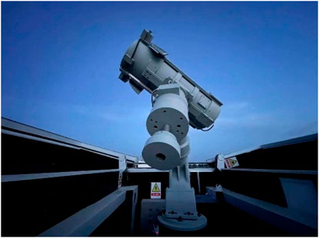
FIGURE 1. A 36 cm telescope in Korla observatory, deployed in early 2021.
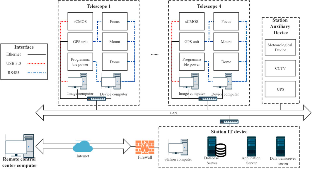
FIGURE 2. Hardware layout of Korla observatory. There are four 36 cm telescopes deployed at this modest observation site. The network port, USB 3.0, and RS485 are utilized to connect each component of the telescope as a whole (including the optical tube, mount, sCMOS camera, dome, and other additional components). Finally, the observatory’s lone communication outlet is linked to the remote control center through the Internet.
2.2 Hardware components
2.2.1 Telescope, mount, camera, and dome
Although program-controlled equipment has been relatively common, there are still few COTS (commercial-off-the-shelf) telescopes that meet the needs for robotic observation of space debris. So, some hardware has been upgraded to fit our needs, allowing the telescope to perform better and adapt to tracking and surveying objects in varied orbits.
The whole telescope system is a passive optical approach to observe space debris. The optical tube of this telescope is improved from the Celestron 36 cm Rowe-Ackermann Schmidt Astrograph (RASA) telescope, which has an aperture of 355 mm, a focal length of 790 mm, and an optical field of view of 4.3°. Based on the original structure, the structural strength is improved, and automatic equipment such as the electric focuser (deploy at the front end of the tube, focusing is realized by moving the camera.) and electric lens cover are added, which makes it more suitable for the application of SSA and other space surveillance applications.
The mount is used to support the optical tube to complete the pointing of the object. In order to realize LEO object tracking and high-speed slew, the manufacturer adopts equatorial mechanical structure, and uses an incremental encoder (resolution: 5 nm) to obtain high-precision position information and brushless permanent magnet synchronous torque motor (continuous torque: 68 nm, continuous speed for continuous torque: 100 rpm) to drive the mount to rotate at high speed, realizing a maximum speed of about 20°/s and a maximum acceleration of about 10°/s2.
The camera, one of the most important components to determine the performance of the system, adopts a high sensitivity, high frame rate, and large target area front-illuminated sCMOS camera (4,096 × 4,096 pixels, 9 μm pixels size, 10 fps, manufactured by Tucsen Photonics, Fujian, China). The Peak quantum efficiency (QE) is 74%@600 nm and the readout noise is about 3.6e-. The optical system of the lens tube covers a wavelength range of 450–850 nm, which is basically within the highest quantum efficiency range of the sCMOS camera (the average QE is more than 60% in the range of 400–750 nm). So, the combination of optical system and camera gives each basic imager a field of view of about 2.6° × 2.6°.
One difference from traditional astronomical telescopes is that our system is not equipped with a filter system. Because the front of the optical lens tube is a little crowded, it also maximizes the light collection efficiency when used without the filter.
The dome is used to protect the telescope. We chose a steel structure box customized by the manufacturer, which is 2.5 m high * 2 m wide * 3 m long, and opened from the middle to both sides. The main reason for choosing such a structure is that it is relatively simple and cheap compared with the traditional full-open shell dome structure.
2.2.2 Additional components
The tracking of space debris requires high time accuracy. So, a GPS unite (manufactured by Baijun Electronic Tech., Xi’an, China) is integrated into the system, and the synchronization accuracy is better than 100 ns. Moreover, since the mount and camera have their own time locking devices and programs, as long as the GPS device transmits reference pulse signals to each piece of equipment with high precision, the time of the whole system can be unified to ensure the exposure accuracy of the camera and the pointing accuracy of the mount. As for IT devices including computers, the system’s NTP (Network Time Protocol) network timing service will be used to maintain the consistency of time.
At the same time, other auxiliary hardware, such as meteorological system (the brand is Vantage Pro2, manufactured by Davis Inst., California, United States), Closed-Circuit Televisions (CCTV) (with infrared camera function, manufactured by Hikvision, Hangzhou, China), and programmable power supply device, are equipped to provide auxiliary parameters required for robotic operation and ensure the safety of the telescope system. Finally, two workstations are used for a single telescope, one for the control of all equipment and one for data processing, as shown in Figure 2.
2.3 Software
2.3.1 System architecture and interaction
The software system is a critical component in achieving the robotic operation of the entire telescope system. Many professional telescopes or telescope networks have developed corresponding control systems to meet their specific needs. ASCOM (Astronomy Common Object Model) and RTS2 (Remote Telescope System 2nd Version) (Kubanek, 2010) are the most frequently used. ISON (Elenin and Molotov, 2020) and BOOTES (Burst Observer and Optical Transient Exploration System) are two examples of successful projects. However, with the upgrading of network technology, a better network framework can be used.
At present, the commonly used communication frameworks include: EPICS (Experimental Physics and Industrial Control System), CORBA (Common Object Request Broker Architecture), ICE (Internet Communications Engine), DCOM (Distributed Component Object Model), and ZMQ (ZeroMQ). Li et al. (2021) analyzed and compared these frameworks, and found that ICE, EPICS, and TANGO are more suitable for building control systems. While Tz et al. (2013) had chosen ZMQ to replace COBRA for TANGO software in 2013. So, our software framework adopts the ZMQ communication component (Dworak et al., 2012) to realize message bus communication, which has also been verified on many telescopes (Lyard et al., 2015; Wang et al., 2021). ZMQ provides sockets that carry whole messages across various transports. And the ZMQ asynchronous I/O model is suitable for scalable multicore applications (Tz et al., 2013).
Based on the experience of previous researchers (Zhang et al., 2016; Dyer et al., 2020; Wang et al., 2021), the control system is basically divided into a multi-layer architecture. So, this system will consist of the following three levels: instrument interface layer (that is Instrument Control System, ICS), telescope control layer (that is Telescope Control System, TCS, including Data Process System, DPS), and business layer (that is Observation Control System, OCS, including User Interface, UI). However, because these telescopes need to be remotely controlled, a Telescope Network Schedule System (TNSS) will be developed to realize the optimal scheduling of multiple pieces of equipment. The final software architecture is shown in Figure 3.

FIGURE 3. The overall architecture diagram.
In terms of single telescope control, the system is developed layer by layer according to three conventional levels, as depicted in Figure 3. The instrument interface layer integrates all real devices to realize Input/Output (IO) control. ZMQ is adopted in this system to realize the communication of different devices in different environments (such as different computers, operating systems, or different interface languages, etc.). The telescope control layer realizes the logical control of each device, defines various Process Variables (PV), and implements some complex commands, such as meridian flipping, star tracking, and image processing. The business layer schedules all devices to complete users’ tasks automatically and responds to changes in the PV of each device.
As for remote networking control of telescopes, the remote scheduling layer will play its role. Its core function is to formulate observation plans for optimization and ensure the maximization of the observation efficiency of all networking telescopes. Furthermore, the remote GUI in this layer mainly provides a human-computer interaction interface for personnel on duty, astronomers, equipment maintenance personnel, and managers, and remotely manages and controls the telescopes. The local status information will be continuously sent to the central database through the Internet.
The OCS of the telescope also draws lessons from the function of RTS2 and adopts distributed programming logic to design and realize a robust and easy to expand control system. The overall language is based on a hybrid of Python and C++. The Python language is mainly used for framework development, business process processing, and hardware execution scheduling. The modules that require high-performance computing and high-speed communication adopt C++, which mainly involves the realization of camera communication, image data gathering and processing, and other functions.
Next, this paper will describe several function points from the perspective of space debris observation.
2.3.2 Tasking
With the increasing amount of space debris and the deployment of more and more telescopes, the effective use of telescopes is particularly important. Since the amount of space debris is considerably greater than the number of telescopes, it is a classic N-P hard problem to figure out how to use the minimum cost to meet the observation needs of diverse tasks. Therefore, many works will adopt some intelligent optimization algorithms to solve such complex problems.
The mode of direct remote control by the control center is used due to the rich computing resources and basic orbit database. Then, the system integrates the Particle Swarm Optimization (PSO) algorithm (Jiang et al., 2017) to establish the central task scheduler of TNSS. The central scheduler will select the working telescopes according to the working state of each telescope and the station environment every day, then select the object to be observed based on the daily task requirements, and then make orbit prediction according to the prior information of these objects, so as to formulate an efficient and practical observation plan for each telescope.
In general, task priority is the most important consideration in the optimal scheduling of the whole observation network. It determines the satisfaction of observation requirements of users in the final decision of an intelligent algorithm. The Table 1 shows the classification of specific tasks by the system.
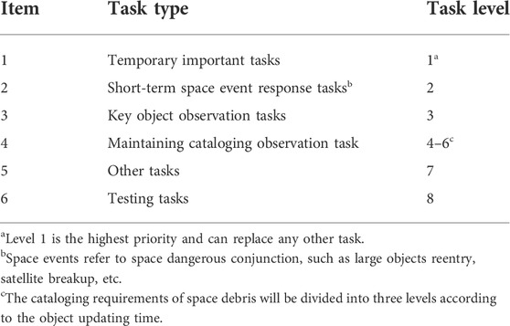
TABLE 1. Definition of task-level under different tasks.
At the same time, some observation details must be considered while optimizing the observation plan, such as observation elevation, the phase angle of Sun and moon, the object switching time, etc. By adjusting the weight of these factors, we can finally make full use of time to complete the observation task, then automatically distribute it to telescopes.
2.3.3 Automatic observation
When the telescope receives the observation plan, it can automatically perform the task. The core of cooperative scheduling of devices by actuators in the business layer is to adopt the timeline-based mode. The received plans or commands to be executed are decomposed into conflict-free time task queues of each device according to the state of each device, and then the actuators of each device are distributed to each device in real-time according to the time sequence. In addition, the actuator can arbitrarily add, delete, and modify the task queue of each device, to make timely modifications in the case of task insertion, equipment failure, or a sudden change of weather, for example.
Figure 4 depicts the core process of the automatic observation process of space debris. Firstly, the scheduler in the control center will analyze the observation demand of the day, and formulate an observation plan for each telescope. Then, after receiving the plan, the local OCS service will analyze the equipment’s working condition as well as environmental information. When the observation threshold is reached, the telescope equipment will be automatically powered on step by step to make various preparations before observation, such as the flat. If the observation conditions do not meet the requirements, the system will wait until the end of the whole observation task. So, when the observation is ready, the actuator will begin loading the observation objects one by one, and then coordinate the rotation of the mount, camera exposure, and DPS to process the data. Various task data and working condition data will be sent back to the control center in real-time and backed up in the local database till the observation task is completed. In this process, the exception handling system (described in Section 2.3.4) always monitors the status of all equipment and the meteorological environment. If an anomaly is detected, the system will make corresponding disposal decisions according to the established operation strategy.
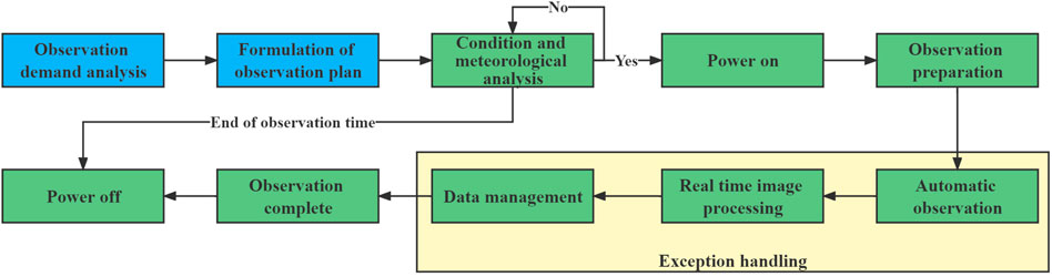
FIGURE 4. Observation process of the whole system.
In addition to conventional observation tasks, the system also presets other automatic task scripts, such as flat exposing, dark exposing, focusing, etc., which are executed after reaching the preset conditions or after manual commands.
2.3.4 Exception handling
It was necessary for a system without human supervision to have a robust and reliable mechanism, which can take corresponding protective measures according to the risk degree of exception. Therefore, three daemons have been set up. One is the weather conditions, the other is the status of the telescope, and the last one is the observation execution results.
The daemon of weather conditions and telescope status are relatively easy to implement. Usually, the daemon processes the collected data (such as rain, temperature, wind speed, etc.) into three status flags according to the corresponding threshold: normal, warning, and error. When an error flag from a weather condition is received, for example, the system will be able to protect the telescope according to the established processing flow (such as stopping the observation task and closing the dome).
As for observation task exception handling, more empirical strategies are needed to deal with it. So, this daemon adopts the Strategy Pattern (SP) mode to realize the flexible combination, addition, deletion, and management of various specific strategies in later use. Take the example of no target found in the image, shown in Figure 5; specific strategies such as changing the camera exposure time (the function of ChangeExpTime), terminating the current tracking plan and searching in a certain area (the function of StartSurvey), and terminating the current tracking plan and waiting along the trace direction in advance (the function of WaitAdvance) are defined. The function of NotTargetStrategy is used to set and select exception handling strategy. Finally, the class of UpdateTask can update the task according to the system status when the task fails.

FIGURE 5. UML diagram of task failure exception handling.
3 Result
The development of the remote automatic control system for the space debris telescope introduced in this paper began in early 2020. With the deployment of four 36 cm telescopes in Korla City, Xinjiang, China in early 2021, the whole system began to operate. The users can carry out remote Internet control on these four telescopes in the duty room in our control center, and carry out observation experiments of conventional space debris and asteroids. Next, some results of the experiment are briefly described.
3.1 Examples for space debris detection
After the installation and commissioning of the telescope, we tested the performance of the telescope. Figure 6 shows the origin images captured by the 36 cm telescope in various modes. Due to its high-speed tracking ability, the telescope can track the LEO small satellite of the Starlink, as shown Figure 6A. Similarly, this large field of view telescope can survey and observe multiple objects. As shown in Figure 6B, six GEO objects are captured in one picture.
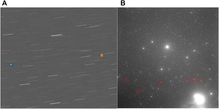
FIGURE 6. The observed images in different modes. (A) The observation image of the Starlink satellite, two satellites were captured in one image; (B) the GEO object image in stellar velocity (about 15″/s) observation mode, six objects were observed at the same time.
3.2 Telescope performances
Stable tracking is the premise for the telescope to obtain effective data. Figure 7 shows the tracking performance of the telescope. We selected the GPS satellite (in MEO and GEO) with high-precision ephemeris to conduct the tracking experiment, and then obtained its tracking error of telescope by comparing the observed data with the high-precision orbit data published by the satellite. As can be seen from Figure 7, the tracking accuracy of the telescope obtained by tracking four GPS satellites in MEO is basically maintained at 1-2 arcseconds. It is worth noting that the tracking accuracy here actually includes a combined error of telescope tracking and data processing.
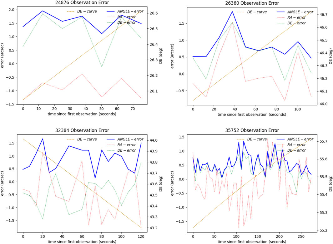
FIGURE 7. The tracking performance of the telescope. The NORAD code of the four GPS satellites (in MEO) are 24,876, 26,360, 32,384, and 35,752 respectively. The blue line (ANGLE-error) represents error synthesized by the two axes, the red line (RA-error) and green line (DE-error) represent the error of the right ascension axis and the declination axis respectively, and the brown line (DE-curve) represents the change of the declination value in the observation tracklets.
We also conducted long-term monitoring of the ultimate detection capability of the 36 cm telescope. To begin with, we chose Gaia (Brown et al., 2018) as the reference star catalog, with a passband that covers the range [330, 1,050] nm, which covers our spectral range. Furthermore, the catalog has announced 1.69 billion, and its limit magnitude has reached 20.7 mV, which can better meet the test requirements. The object position and magnitude are then extracted using the SExtractor software package (Bertin and Arnouts, 1996), and the real star position and magnitude in the image are filtered through star catalog matching. Finally, the magnitude of the darkest objects in the image is filtered.
From 10:00 p.m. to 11:00 p.m. (Beijing Time), we captured at least 10 images (exposure time: 10 s, tracking star mode) to calculate the average value on the same sky area. Furthermore, the weather is not always pleasant. Because the clouds can be dense on some evenings, we decided to observe for 1 month. Furthermore, the pointing area and time each night are slightly adjusted according to the actual situation. Figure 8 shows the change in the limiting magnitude of the telescope in a month. It can be seen that, under the condition of the crescent moon (around 2 January 2022), the performance of the telescope can reach 16.6 mV, and when the moon is full (around 19 December 2021), the limit performance is reduced to 15.4 mV. This performance has achieved relatively good results in telescopes with the same aperture, and this is the result after almost 1 year of installation. The dust accumulation on the mirror and the decline of the camera performance are inevitable. At the same time, it should be emphasized that the results obtained by us are not strictly the atmospheric apparent magnitude of the star, since we ignored some errors, such as the influence of atmospheric extinction, and used the standard filter system.
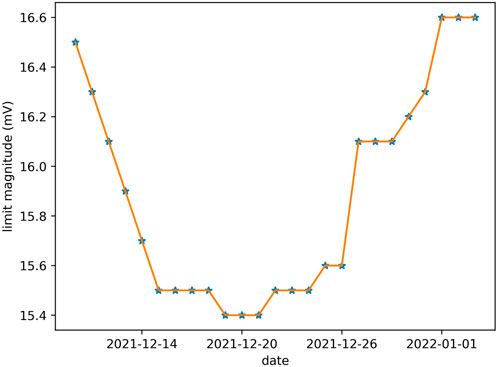
FIGURE 8. The change of the limiting magnitude (tracking star mode) with a 10 s exposure time of the 36 cm telescope in a month (from 2 December 2021 to 3 January 2022). Every night, the same sky area was selected to take images from 10:00 p.m. to 11:00 p.m., and the limit magnitude of each day was calculated, which is represented by an asterisk in the figure.
Image quality and focusing performance are also important factors that determine the final performance of the system. We defined the Full-Width Half Maximum (FWHM) of the image as the index to evaluate the image. We used the Sextractor package to calculate this value. When the threshold of FWHM is larger than 2 pixels, the system will automatically focus according to the V-curve method. Figure 9 shows a focusing process curve and the actual image. The 36 cm telescope usually takes images one by one with a focusing step of 0.05 mm to obtain the FWHM at each position (usually five images are taken before and after the current position). Finally, the best focusing position is obtained through the quadratic curve.
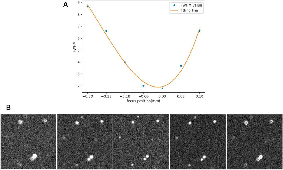
FIGURE 9. The result of FWHM curve fitting using the V-curve method. (A) Diagram of curve fitting. The X-axis is the focal position and Y-axis is the mean FWHM value of the image. (B) The sequence of images on different focal position.
3.3 Statistics
The ultimate goal of the whole system is to obtain the position of the space debris. Figure 10 shows the number of object’s arcs successfully observed and extracted by a single 36 cm telescope from 2 December 2021 to 3 January 2022. As shown in the figure, approximately 3,300 object arcs were successfully extracted over the observation period, and observation data are obtained every night. Therefore, in terms of the overall numbers, the effect of the telescope is still good. However, the number of arcs fluctuates substantially, with at least 23 arcs and a maximum of 163 arcs. While the data observation plan tracks about 160 space debris arcs every night (the solar altitude angle of −8° is set as the flag of the beginning and end of observation, GEO tracking takes place for 6 min and LEO tracking for 3 min). Moreover, the highest success rate of actual observation (the number of arcs actually observed in the planned arcs/the number of planned arcs) is about 78%, on December 11 and 30, which is a little insufficient to satisfy our requirements. There may be several reasons.
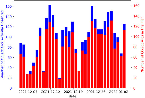
FIGURE 10. The number of objects arcs successfully observed and extracted by a single 36 cm telescope from 2 December 2021 to 3 January 2022. The blue bar represents the number of object arcs actually observed. The red bar represents the number of object arcs in the plan.
First, it can be noticed that there are several unplanned objects every night. Because our telescope has a field of view of 2.6°, we can capture multiple objects in one image. As a result, unplanned objects are likely to be obtained. Second, the optical telescope is still too weather-dependent. On several evenings, such as December 4 and 5, the humidity hit the 85 percent threshold specified by us, which automatically halted the observation task, resulting in an insufficient observation data. Then, clouds, as well as dust in the air, were particularly terrible, particularly on December 9, 14, 20, etc. When observing, the image has only a few stars or no stars, making subsequent astronomical positional processing and even simple object extraction impossible.
4 Discussion
This system is designed as a telescope system dedicated to space debris and asteroid observation. The slewing speed of the telescope mount is enhanced in hardware to switch object faster. The equipped sCMOS camera can generate images with a high frame rate (10 Hz, regardless of storage conditions), and capture more data for LEO objects. The installation of electric focusing, electric lens covers, and other facilities have transformed the original amateur telescope into a professional space debris observation telescope. Although it will be unable to conduct a certain study on object characteristics due to the lack of a filter system, it will ensure the telescope system’s ability to collect light to some extent. After all, the primary goal of the system is to acquire information on the position of space debris.
From the results of the telescope system deployed in Korla, this 36 cm telescope can perform the tracking and observation task of objects in various orbits, and the tracking error within 1–2 arcseconds also ensures the accuracy of observation data. The limiting magnitude capability of about 16 mV (10 s exposure with tracking star mode, without considering atmospheric extinction and color index of filter system) will also meet the detection of medium and large-scale space debris. Through the optimal scheduling and robotic operation of the system, the telescope can collect a large amount of data in a short time, for example, a single telescope can track more than 100 space objects arcs on average. The weather of observation site has an impact on the observation arc’s quantity. Because of the close proximity to the desert, sand and dust are frequently hung in the air when the wind blows. Furthermore, urban lighting has an impact on the observation of low elevation. So, in general, we cannot label this site a great astronomical site, but rather an acceptable site that can match the objectives of space debris observation while also allowing us to conduct network experiments. Finally, we are currently focusing on tracking and observing certain objects of interest, but if we switch to a survey mode, such as a GEO belt survey, the number will greatly grow due to the big field of view.
The successful implementation of this system demonstrates that it is relatively easy to construct a simple automatic control system. Compared with the current ASCOM and the RTS2 framework, the technical route adopted by this software is simpler and makes the secondary development freer. Generally, the commercial hardware devices have completed the underlying control algorithm. So, the interface provided for user development is relatively simple. Users just need to pay attention to the top architecture and the integration of various devices during software development. For example, in this system, the core interface of the mount has 3 parameters: time, two angles, and two angle speed. The core interface of the camera has two parameters: start exposure time and exposure time. Then, the OCS and TCS send the command to a device in time according to the established time line, and immediately complete the control of the device. In addition, the system adopts mature message middleware ZMQ to solve the communication problems between the center and local, as well as between different equipment interfaces and different systems; the control strategy is written in Python, which has a low learning cost and is easier to implement. However, it should be considered that the GIL lock of Python will result in poor calculation speed and I/O interaction, so it is necessary to adopt multi-process and C++ for modules requiring fast calculation. Furthermore, some mature astronomical packages may be used for data processing, such as SExtactor, Astrometry.NET (Lang et al., 2010), and others, to retrieve the position, magnitude, image quality, and other information of the observation object we require.
However, it must be recognized that, compared with the mature international monitoring networks such as ISON and FTN telescope, we still have a lot of work to do. First of all, we should actively expand the breadth of equipment deployment areas, which will also promote the upgrading of our software system. Secondly, the system’s perception of anomalies needs to be further improved, especially the weather perception ability. Due to the desert edge where the telescope is deployed at present, there is little rain and the possibility of sudden change of weather is low. So, once the telescope is deployed to the weather changeable area, the system needs to analyze and predict in combination with the cloud images, wind speed, humidity, and other data collected in real-time, to ensure the safety of unattended equipment. Finally, the next thing we need is to enhance the real-time collaborative scheduling of telescopes. For example, when a single telescope finds a new object, it can schedule another telescope for follow-up tracking, involving single station multi-device collaboration, as well as multi-station multi-device collaboration, which will also promote the upgrading of image processing speed, fast target recognition, and other capabilities.
5 Conclusion
Driven by the current demand for space debris and asteroid observation, this paper introduces feasible telescope software and a hardware scheme. The 36 cm RASA tube with 4 K sCMOS forms a 2.6°*2.6° large field telescope, with high precision tracking of space debris in LEO, MEO, and GEO. Many auxiliary devices also help the system become a robotic telescope. Since the deployment, the telescope has been working well and has obtained a lot of observation data of space debris.
Regarding the software system, this paper introduces the overall software framework. Based on ZMQ control architecture, we establish a lightweight cross-system and distributed system to facilitate the addition or deletion of subsequent devices. According to the observation process of space debris, each functional module is designed. And this paper focuses on the realization of automatic operation and exceptional handling functions. This system greatly reduces the dependence on telescope operation and maintenance personnel. The remote unmanned operation of four telescopes proves the feasibility of this scheme, which will be extended to other telescopes in the future.
With the accumulation of operation experience, the system will further optimize the robustness of the telescope’s remote automatic control software and improve the control ability of the telescope, to cope with the more complex observation environment, strengthen the collaborative control between telescopes, and give full play to the greater efficiency of the equipment.
Data availability statement
The raw data supporting the conclusion of this article will be made available by the authors, without undue reservation.
Author contributions
SJ and CH-W contributed to conception, design and implementation of the whole software. JH contributed to the design of scheduling software. JH and ZY-Y contributed to the design of the image process software. LJ contributed to the design of operation mode. SJ wrote the first draft of the manuscript. All authors contributed to manuscript revision, read, and approved the submitted version.
Funding
We acknowledge the financial support from the Space Debris and Near-Earth Asteroid Defense project of China (Nos. KJSP2020020201, KJSP2020020202, and KJSP2020020204) and the National Natural Science Foundation of China (No. 11803052).
Conflict of interest
The authors declare that the research was conducted in the absence of any commercial or financial relationships that could be construed as a potential conflict of interest.
Publisher’s note
All claims expressed in this article are solely those of the authors and do not necessarily represent those of their affiliated organizations, or those of the publisher, the editors and the reviewers. Any product that may be evaluated in this article, or claim that may be made by its manufacturer, is not guaranteed or endorsed by the publisher.
References
Bertin, E., and Arnouts, S. (1996). SExtractor: Software for source extraction. Astron. Astrophys. Suppl. Ser. 117, 393–404. doi:10.1051/aas:1996164
Brown, A. G. A., Vallenari, A., Prusti, T., et al. (2018). Gaia Data Release 2. Summary of the contents and survey properties, Astronomy & Astrophysics. 616(A1). 22, doi:10.1051/0004-6361/201833051
Castro-Tirado, A. J. (2011). Robotic astronomy and the BOOTES network of robotic telescopes. Acta Polytech. 51 (2), 16. doi:10.14311/1308
Chun, F. K., Tippets, R. D., Strong, D. M., et al. (2018). A new global array of optical telescopes: The falcon telescope network. Publ. Astronomical Soc. Pac. 130 (991), 095003. doi:10.1088/1538-3873/aad03f
Crowther, R. (2002). Orbital debris: A growing threat to space operations. Philosophical Trans. R. Soc. A Math. Phys. Eng. Sci. 361 (1802), 157–168. doi:10.1098/rsta.2002.1118
Dworak, A., Ehm, F., Charrue, P., and Sliwinski, W. (2012). The new CERN controls middleware. J. Phys. Conf. Ser. 396 (1), 012017. doi:10.1088/1742-6596/396/1/012017
Dyer, M. J., Dhillon, V. S., and Littlefair, S., (2020). Developing the GOTO telescope control system, SPIE. 11452, 114521–114612. doi:10.1117/12.2561506
Elenin, L. V., and Molotov, I. E. (2020). Software for the automated control of robotic optical observatories. J. Comput. Syst. Sci. Int. 59 (6), 894–904. doi:10.1134/s1064230720040036
Jiang, H., Liu, J., Cheng, H., and Zhang, Y. (2017). Particle swarm optimization based space debris surveillance network scheduling. Res. Astron. Astrophys. 17, 30. doi:10.1088/1674-4527/17/3/30
Kennewell, J. A., and Vo, B. N. (2013). An overview of space situational awareness, in Proceedings of the 16th International Conference on Information Fusion, Istanbul, Turkey, 09-12 July 2013, IEEE, 1029–1036.
Kubanek, P. (2010). RTS2-The remote telescope system. Adv. Astronomy 2010, 9. doi:10.1155/2010/902484
Lang, D., Hogg, D. W., Mierle, K., Blanton, M., and Roweis, S. (2010). Astrometry.net: Blind astrometric calibration of arbitrary astronomical images. Astronomical J. 139 (5), 1782–1800. doi:10.1088/0004-6256/139/5/1782
Li, J., Wang, N., Liu, Z., Song, Y., Li, N., Xu, L., et al. (2021). Trends in architecture and middleware of radio telescope control system. Adv. Astronomy 2021, 1–10. doi:10.1155/2021/2655250
Lyard, E., Walter, R., and Kosack, K., (2015). Modern middleware for the data acquisition of the cherenkov telescope array.
Martone, R., Guidorzi, C., Mundell, C. G., Kobayashi, S., Cucchiara, A., Gomboc, A., et al. (2019). A robotic pipeline for fast GRB followup with the Las Cumbrés observatory network. Exp. Astron. (Dordr). 48 (1), 25–48. doi:10.1007/s10686-019-09634-y
Molotov, I., Zakhvatkin, M., Elenin, L., Canals Ros, L., Graziani, F., Teofilatto, P., et al. (2019). Ison network tracking of space debris: Current status and achievements. RMxAC. 51, 144–149. doi:10.22201/ia.14052059p.2019.51.25
Park, J., Yim, H., Choi, Y., Jo, J. H., Moon, H. K., Park, Y. S., et al. (2018). OWL-Net: A global network of robotic telescopes for satellite observation. Adv. Space Res. 62 (1), 152–163. doi:10.1016/j.asr.2018.04.008
Seitzer, P., Smith, R., Africano, J., Jorgensen, K., Stansbery, E., and Monet, D. (2004). MODEST observations of space debris at geosynchronous orbit. Adv. Space Res. 34 (5), 1139–1142. doi:10.1016/j.asr.2003.12.009
Tz, A. G., Taurel, E., Verdier, P., et al. (2013). TANGO–Can ZMQ replace CORBA? in Proceedings of ICALEPCS, San Francisco, CA, USA, November 2013.
Wang, Z., Tian, Y., Li, J., Cao, Z. H., and Zhao, Y. H. (2021). A study on universal observation control system and its application for LAMOST. Res. Astron. Astrophys. 21 (6), 149. doi:10.1088/1674-4527/21/6/149
Keywords: space debris observation, telescope control system, robotic control, ZeroMQ, optical telescope, networking scheduling
Citation: Sun J, Cheng H-W, Jiang H, Liu J and Zhao Y-Y (2022) A 36 cm robotic optical telescope: Equipment and software. Front. Astron. Space Sci. 9:897065. doi: 10.3389/fspas.2022.897065
Received: 15 March 2022; Accepted: 13 June 2022;
Published: 23 August 2022.
Edited by:
Frederic Victor Hessman, Institut für Astrophysik, Georg-August-Universität Göttingen, GermanyReviewed by:
Bjoern Poppe, University of Oldenburg, GermanyChuanjun Wang, National Astronomical Observatories (CAS), China
Copyright © 2022 Sun, Cheng, Jiang, Liu and Zhao. This is an open-access article distributed under the terms of the Creative Commons Attribution License (CC BY). The use, distribution or reproduction in other forums is permitted, provided the original author(s) and the copyright owner(s) are credited and that the original publication in this journal is cited, in accordance with accepted academic practice. No use, distribution or reproduction is permitted which does not comply with these terms.
*Correspondence: Jian Sun, sunjian@nao.cas.cn