The high energy X-ray probe (HEX-P): instrument and mission profile
 Kristin K. Madsen1*
  Javier A. García1,2
  Daniel Stern3
  Rashied Amini3 Stefano Basso4 Diogo Coutinho5 Brian W. Grefenstette2 Steven Kenyon1
  Alberto Moretti4 Patrick Morrissey3 Kirpal Nandra5
  Giovanni Pareschi4
  Peter Predehl5
  Arne Rau5 Daniele Spiga4
  Jörn Wilms6 William W. Zhang1
- 1X-ray Astrophysics Laboratory, NASA Goddard Space Flight Center, Greenbelt, MD, United States
- 2Cahill Center for Astrophysics, California Institute of Technology, Pasadena, CA, United States
- 3Jet Propulsion Laboratory, California Institute of Technology, Pasadena, CA, United States
- 4INAF-Osservatorio Astronomico di Brera, Brera, Italy
- 5Max Planck Institute for Extraterrestrial Physics, Garching, Germany
- 6Department of Physics Dr. Karl Remeis-Observatory Bamberg, Friedrich-Alexander-Universität, Erlangen-Nürnberg, Erlangen, Bayern, Germany
The High Energy X-ray Probe (HEX-P) is a proposed NASA probe-class mission that combines the power of high angular resolution with a broad X-ray bandpass to provide the necessary leap in capabilities to address the important astrophysical questions of the next decade. HEX-P achieves breakthrough performance by combining technologies developed by experienced international partners. To meet the science goals, the payload consists of a suite of co-aligned X-ray telescopes designed to cover the 0.2–80 keV bandpass. The High Energy Telescope (HET) has an effective bandpass of 2–80 keV, and the Low Energy Telescope (LET) has an effective bandpass of 0.2–20 keV. HEX-P will be launched into L1 to enable high observing efficiency, and the combination of bandpass and high observing efficiency delivers a powerful platform for broad science to serve a wide community. The baseline mission is 5 years, with 30% of the observing time dedicated to the PI-led program and 70% to a General Observer (GO) program. The General Observer program will be executed along with the PI-led program.
1 Introduction
The current landscape for large X-ray missions is dominated by oversubscribed observatories far into their extended operation phase. The next planned flagship-class X-ray observatory is the ESA Athena mission, currently scheduled to launch no earlier than 2037. With the current outlook, the science community faces a non-negligible risk of being without a sensitive X-ray GO observatory in the 2030s, which is particularly alarming given the extensive number of time domain and multi-messenger astrophysics (TDAMM) facilities coming online over the next decade and the critical role high-energy observations play in understanding the physics of explosive and energetic phenomena (e.g., Brightman et al., 2023). HEX-P is designed to bridge this gap and complement Athena once it launches, with instrumentation that will deliver capabilities to advance our understanding of the X-ray Universe across a breadth of topics.
The Nuclear Spectroscopic Telescope Array (NuSTAR) (Harrison et al., 2013), a NASA Small Explorer mission, opened the high-energy (
HEX-P will be launched into L1, which provides

FIGURE 1. Time to obtain 100 supermassive black hole (SMBH) spin measurements with HEX-P compared to NuSTAR observations coordinated with soft X-ray observatories (primarily XMM-Newton). The number of spin measurements obtained with NuSTAR are collected from published papers and demonstrates that at the current rate, which is limited by the coordinated observing time, it would take about 30 years to obtain 100 spin measurements through GO programs.
2 Observatory and mission overview
The HEX-P payload consists of a suite of three co-aligned X-ray telescopes designed to cover the 0.2–80 keV bandpass. The High Energy Telescope (HET) has an effective bandpass of 2–80 keV and is composed of two High Energy Mirror Assemblies (HEMAs), which utilize thin electroformed Ni shells coated with Pt/C and W/Si multilayer coatings for high energy response. These focus on two High Energy Detector Assemblies (HEDAs), which are photon counting CdZnTe (CZT) hybrid detectors based on the NuSTAR design. The Low Energy Telescope (LET) has an effective bandpass of 0.2–20 keV and is composed of a Low Energy Mirror Assembly (LEMA) optimized for improved spatial resolution that capitalizes on Si segmented mirror technology developed at the NASA Goddard Space Flight Center (GSFC). The LEMA focuses on the Low Energy Detector Assembly (LEDA), which utilizes a Depleted P-Channel Field Effect Transistor (DEPFET).
The HEX-P instrumentation is shown in Figure 2. The three Wolter type I (Wolter-I) telescope mirror assemblies are mounted to a Northrop Grumman three-axis stabilized spacecraft bus that serves as the base for a three-sided, coilable boom, extended after launch to place the detector bench at a focal length of 20 m. The coilable boom is enclosed in a thermal Kapton sock to suppress stray light and bremsstrahlung activation of the boom components by solar X-ray flux. The boom deploys with an array of three aperture stops to mitigate stray light from sources outside the field of view (FoV) and the cosmic X-ray background (CXB).
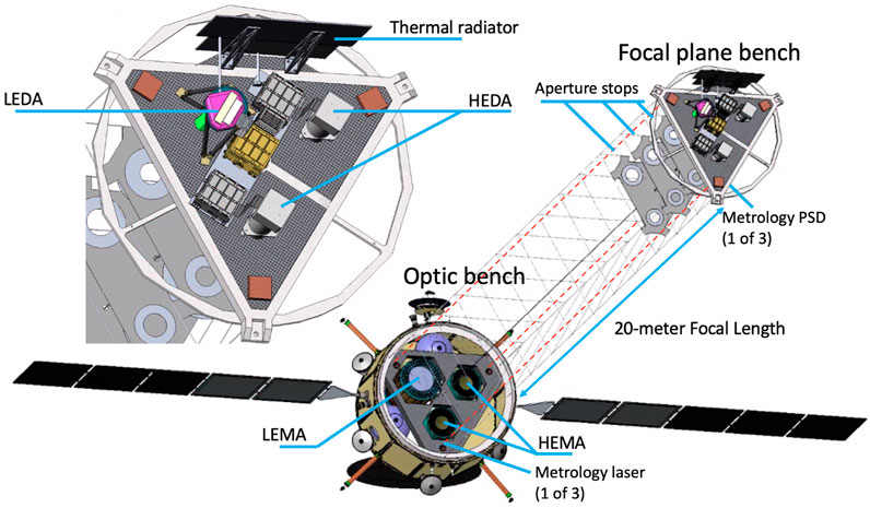
FIGURE 2. Three Wolter-I mirror assemblies are mounted rigidly onto the spacecraft structure and connected to a composite focal plane bench by a 20-m long, three-sided, coilable boom. A metrology system comprised of three laser-detector pairs provides real-time tracking of displacements between the benches that are used to reconstruct images from time-resolved data during post-processing. The aperture stops interior to the boom provide background mitigation from stray-light and the diffuse cosmic X-ray background.
A metrology system (MET), comprised of three parallel diode lasers mounted to the optics bench and co-aligned with the telescopes, forms a reference for three position-sensitive detectors (PSDs) mounted at the focal plane bench. The MET tracks the motions of the boom during observations, while three bus-mounted star trackers provide an absolute pointing reference that is combined with the laser metrology to reconstruct data on the ground.
The baseline mission is 5 years, with 30% of the observing time dedicated to the PI-led program and 70% to a GO program. The GO program will run alongside the PI-led program, and all data will be made available without proprietary time.
3 Payload instruments
3.1 The high energy telescope: HET
The HET consists of the two HEMA optics, which are co-aligned and observe the same field. These two mirror assemblies are identical and coated with Pt/C and W/Si multilayers to achieve the broad bandpass response. The HET optics design and implementation rely on previous developments carried out in Italy for the Simbol-X and NHXM mission studies (Pareschi et al., 2009; Basso et al., 2011; Spiga et al., 2011). The two HEMAs are matched to the HEDAs, which are photon-counting CZT hybrid detectors based on the NuSTAR design built by Caltech. The HET has a FoV of 13.7′ × 13.7′, driven by the detector size, and the mirrors are expected to provide a half-power diameter (HPD) angular resolution of 10″ at 6 keV and 23″ at 60 keV.
The performance presented in this paper corresponds to the instrument specifications that are summarized in Table 1, analogous to the version 7 (v07) instrument design, which was distributed in April 2023 (and are available at https://hexp.org/response-files-2/). For the submission of the proposal in November 2023, the number of HEMA shells was reduced from 60 to 57, resulting in a 12% loss of the HET effective area at energies below 20 keV.
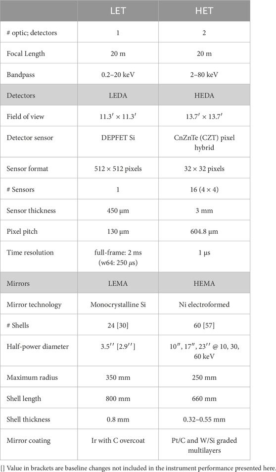
TABLE 1. HEX-P instrument performance (v07).
3.1.1 The high energy mirror assembly: HEMA
The two HEMAs are made from pseudo-cylindrical monolithic shells, replicated from high-accuracy mandrels by means of Ni electroforming (see, e.g., Vernani et al., 2011). This technology has been successfully used for the Ni gold-coated X-ray mirrors of BeppoSAX (launched in 1996), XMM-Newton (1999), Neil Gehrels Swift Observatory (2004), SRG/eROSITA (2019), and the forthcoming Einstein Probe (Vernani et al., 2022).
Each HEMA has 60 (v07) nested Wolter-I paraboloid-hyperboloid mirror shells. The primary design constraint requires that the grazing incidence angle be less than 3.2 mrad. For a focal length of 20 m, this corresponds to an outermost diameter at the parabola-hyperbola intersection plane of approximately 500 mm. Figure 3 shows the reflectivity of a Pt/C multilayer coating optimized for the bandpass, demonstrating that at these angles, the coatings have
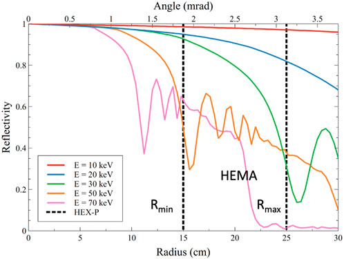
FIGURE 3. Reflectivity curve of a Pt/C multilayer coating as a function of energy.
The multilayers for the HEMA are optimized for bandpass and performance in a well-established process (Madsen et al., 2004; Cotroneo et al., 2009; Madsen et al., 2022). The number of bilayers is
On the basis of the previous experience gained with Ni electroformed shells, in particular eROSITA, an angular resolution of HPD ≤10″ at energies
3.1.2 The high energy detector assembly: HEDA
The design of the HEDA is adapted from flight-proven hard X-ray detectors flown on NuSTAR with over a decade of successful operation in space (Harrison et al., 2013). These hybrid detectors are composed of a monolithic crystal of CZT flip-chip bonded to an Application Specific Integrated Circuit (ASIC) (Chen et al., 2004). To improve the high-energy quantum efficiency (QE), the HEDA uses 3-mm thick CZT rather than the 2-mm thick CZT used on NuSTAR. The dimensions of the individual hybrid detectors remain the same, and due to the longer focal length, each HEDA will use an array of 4 × 4 detectors compared to the NuSTAR 2 × 2 layout. This conserves the FoV to be 13.7′ × 13.7′, as it is for NuSTAR.
The energy resolution is comparable to NuSTAR, with a 500 eV full-width at half-maximum (FWHM) energy resolution below 10 keV, increasing to 850 eV at 60 keV. Improvements to the digital processing and analog-to-digital conversion rates increase the overall throughput of the system by up to 1,000 cps from 400 cps in NuSTAR. The detectors can handle an incidence count rate of 10,000 cps before pile-up becomes an issue. Like NuSTAR, the HEDA is surrounded by an anti-coincidence shield to reduce the background due to charged particles.
3.1.3 HET background
The similarities between the NuSTAR focal plane module (FPM) and the HEDA allow the use of a scaled mass model for a NuSTAR FPM to estimate the non-X-ray background (NXB) contribution from the charged particle flux at L1 using GEANT4 modeling (Madsen et al., 2023b). To eliminate the Cs and I lines between 23 and 28 keV, which arise from the anticoincidence shield that was used on NuSTAR, the HEX-P baseline is BiGeO (BGO), which will produce Ge Kα lines at 9–11 keV and Bi Kα lines at 74–77 keV. For comparison with NuSTAR, simulations were performed for CsI, and the results were used to scale the NuSTAR background. The background was fit with an empirical model, and the Cs and I lines were removed before producing the background instrument file for the simulations.
The HET background contribution from the CXB is determined by the solid angle of the sky that subtends the detectors. Because of NuSTAR’s open structure, it is the dominant background component to the NuSTAR detectors below 20 keV. This is mitigated on HEX-P with a set of aperture stops held inside the boom, which combine with a graded-Z plate to prevent transmission through the bench on the optic bench and narrow the solid angle of the HEDA down to 0.0023 sr. As shown in Figure 4A, this eliminates the CXB background contribution below 20 keV (Madsen et al., 2023b).

FIGURE 4. (A) The HET instrument background is separated into the CXB and NXB. (B) The effective area of the HET, with and without the detector efficiency and other absorbing elements in the X-ray path.
The Sun is a prompt source of soft X-rays and particles, producing a series of flares on timescales of days with rapid decays. Since the periods of high background can be excluded, they are not included in the persistent NXB background estimate.
3.1.4 HET effective area
The effective area of the HEMA was derived from a full ray trace, including all known effects of obscuration, surface micro-roughness, and mirror reflection from multilayers. The QE and redistribution matrix of the HEDA were simulated using the charge transport and detector effects modeling code developed for NuSTAR and validated against flight data. Figure 4B shows the current best estimate of the effective area of the HEMA folded through the HEDA detector redistribution function. The sag in the area around 40 keV can be mitigated with different multilayer prescriptions at a cost in the area around 20 keV.
3.2 The Low Energy Telescope: LET
The LET is composed of one LEMA mirror, which is optimized for improved spatial resolution up to 20 keV and capitalizes on the Si segmented mirror technology developed at the NASA GSFC. At the focus of the LEMA is the LEDA, which utilizes the DEPFET technology developed by the Max Planck Institute for Extraterrestrial Physics (MPE; Garching, Germany) for the Wide Field Imager (WFI) (Meidinger et al., 2020) on the ESA L-class Athena mission (Ayre et al., 2018; Bavdaz et al., 2021). The FoV of the LET is 11.3′ × 11.3′, and the anticipated angular resolution of the LET is projected to be HPD
The performance presented in this paper corresponds to the instrument specifications that are summarized in Table 1, and analogous to the ‘v07’s estimated performance that were distributed in and are available at https://hexp.org/response-files-2/. For the submitted proposal, the number of shells of the LEMA was increased from 24 to 30, resulting in a 35% increase in effective area. In addition, the current best estimate of the LET HPD improved from 3.5″ to 2.9′′.
3.2.1 The Low Energy Mirror Assembly: LEMA
The LEMA uses the single crystal Si mirror technology that has been under development at GSFC by the Next-Generation X-ray Optics team since 2010. It consists of semiconductor-grade monocrystalline segments, approximately 100 × 100 mm2 and 0.8 mm in thickness, that are cut out of a block of Si and polished to an arcsecond figure using lapping and polishing techniques, including ion-beam figuring (Riveros et al., 2022).
The optical design and curvature of the primary and secondary mirror follow a variant of the Wolter-I design that employs a hyperbolic-hyperbolic prescription (Harvey et al., 2001; Saha and Zhang, 2022). In this design, the Wolter-I parabolic primary is replaced with a hyperbolic curvature, which provides superior off-axis angular performance over a conventional Wolter-I design. The LEMA is a segmented mirror with sub-components collected into 18 mirror modules that are arranged in a ring. Due to the long focal length, the mirror modules are required to be 800 mm in length, and each mirror module contains 8 (axial) and 24 (radial) mirror segments (for the v07 design).
The LEMA is baselined with a 10 nm layer of Ir with an 8 nm C overcoat. This coating prescription is identical to what is proposed for Athena (Svendsen et al., 2022). The benefit of the C overcoat is demonstrated in Figure 5: C mitigates absorption occurring from the Ir M-complex, providing a significant improvement in low-energy performance. Further details on the mirror design and coating performance are presented in Madsen et al. (2023a).
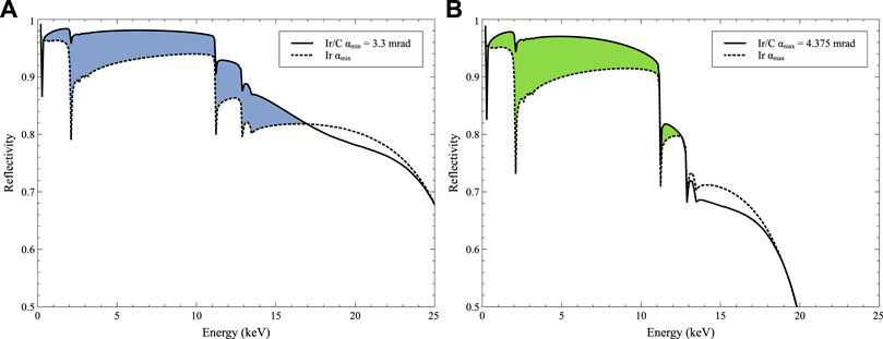
FIGURE 5. The C overcoat provides a significant improvement in reflectivity below 10 keV for a small trade between 15 and 20 keV. (A) Difference in reflectivity between a single Ir coated layer and Ir with a C overcoat for the minimum grazing incidence angle αmin = 3.3 mrad. (B) Difference in reflectivity between a single Ir coated layer and Ir with a C overcoat for the minimum grazing incidence angle αmax = 4.375 mrad.
3.2.2 The Low Energy Detector Assembly: LEDA
The LEDA utilizes one built-to-print detector quadrant of the WFI and packages it into a new housing. At the heart of the detector is the Si DEPFET sensor, which is a sensor-amplifier structure combined with a MOSFET integrated onto a fully depleted Si bulk. The DEPFET sensor is read out using two types of ASICs: the Switcher and the Veritas (Herrmann et al., 2018). These comprise the front-end electronics of the DEPFET detector. The Switcher controls the row-steering of the DEPFET sensor in a rolling shutter mode by applying a sequence of voltages, where rows are read out sequentially, and all pixels of one row are read simultaneously. The Veritas is a low-noise, multichannel amplifier, and shaper circuit with an analog output that serializes the analog signals of the DEPFET pixels, clocking out at a rate of 25.6 MHz. Each pair of Veritas/Switcher handles 64 rows of the DEPFET, and each detector contains 8 ASICs of each type.
The DEPFET detector facilitates state-of-the-art spectral resolution over the required broad energy band from 0.2 to 20 keV, with a FWHM of 80 eV at 1 keV and 150 eV at 7 keV (Figure 6). High QE is achieved by back-illumination of the 450 μm thick sensor. A 5-μm thick benzocyclobutene (C8H8) layer on the off-mirror side is used for passivation, and a 90-nm thick Al coating on the mirror side of the detector serves as an on-chip filter to reduce contamination of the X-ray signal by optical light. A filter wheel provides a 40 nm Al filter for additional optical blocking and contamination control.
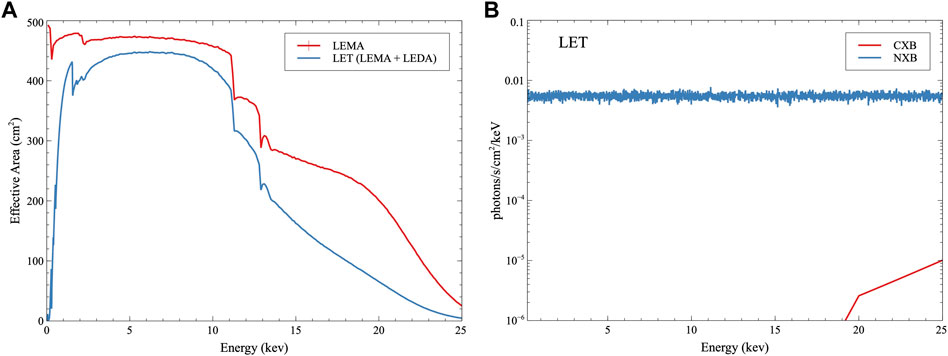
FIGURE 6. (A) Spectral performance of the DEPFET. The listed times are the exposure times and, therefore, the time resolution of the sensor. For the readout, the full exposure time is used, which allows for a better performance at a lower time resolution. The increasing difference between the theoretical Fano limit and the measured performance for lower photon energies is caused by charge losses at the entrance window. Low-energy photons have a lower penetration depth and increased probability of charge losses. (B) Simulated pile-up fraction for HEX-P in full frame or window modes with either 64 (w64) or 128 (w128) rows.
The LEDA is operated at 2 ms frame time (the WFI operates at 5 ms) in full frame mode (i.e., all pixels) at a small cost in energy resolution, as shown in Figure 6A. For bright sources that cause pile-up, the detector can be operated in a window mode that enables a faster readout for fewer rows (in multiples of 64). For the smallest window (w64: 64 × 512 pixels), the detector readout is 250 μs. A Monte Carlo simulation using the SImulation of X-ray TElescopes (SIXTE) (Dauser et al., 2019) software was used to estimate the LEDA pileup percentage as a function of incident count rate using a spectrum of the Crab with a slope of Γ = 2.1. SIXTE contains the DEPFET simulator and can faithfully replicate the readout speed. Combined with the LET mirror effective area, SIXTE can predict the pileup fraction as a function of source flux. This was simulated for the full frame detector and for window modes using 128 or 64 rows. Figure 6B shows that 1% pileup fraction is reached at 20 mCrab for the full detector and 150 mCrab for the 64-row mode. A higher flux limit could be allowed for a flatter spectrum.
Due to the potential for radiation damage from soft protons from the Sun, the LEDA has a magnetic diverter that deflects protons with energies E < 75 keV (Madsen et al., 2023b).
3.2.3 LET Background
The LEDA builds strongly on efforts made for Athena/WFI, and the radiation requirements on the shielding are directly inherited from the WFI (Eraerds et al., 2021). The charged particle background, NXB, is the dominant term and, based on the work done for the WFI (Madsen et al., 2023b), has a mean rate of 6.7 × 10⁻³ photons s−1 cm−2 keV−1 between 0.2–20 keV. This is considered an upper limit since the GEANT4 modeling was performed on the WFI instrument, which has approximately four times the mass of the LEDA.
As for the HET, a set of apertures and a graded-Z shielding plate on the optics bench combine to limit the solid angle of sky subtended by the detectors. Due to the larger aperture of the LEMA, the aperture stop openings also have to be larger than for the HET, and the solid angle of the sky is 0.0048 sr, about twice as large as for the HET. This results in a CXB component of a mean rate of 1.0 × 10⁻⁵ photons s−1 cm−2 keV−1, two orders of magnitude below the NXB as shown in Figure 7A.
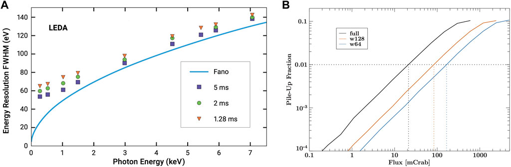
FIGURE 7. (A) The LET instrument background is separated into the CXB and NXB. (B) The effective area of the LET, with and without the detector efficiency and optical blocking filters.
The Sun is a prompt source of soft X-rays and particles, producing a series of flares on timescales of days with rapid decays. Since the periods of high background can be excluded, they are not included in the persistent NXB background estimate.
3.2.4 LET Effective Area
The effective area of the LEMA was derived from a full ray trace, including all known effects of obscuration, surface micro-roughness, and multilayer reflection. The QE and redistribution matrix of the LEDA were simulated using the SIXTE detector simulator and verified against laboratory data. Figure 7B shows the best current estimate of the effective area of LEMA (v07) folded through the redistribution function of the LEDA detector and the optical blocking filters.
4 Instrument sensitivity
Due to the broadband nature of the science objectives and the diversity of spectral features targeted in the source spectra, the HEX-P performance metric is expressed as the minimum detectable flux of a signal-to-noise ratio,
where b is the background flux, t is the exposure time, APSF is the energy-dependent area on the detector covered by the PSF, and AEff is the energy-dependent effective area. The PSF detector area, APSF, is optimized to maximize the signal in the background and has a diameter of
The differential flux of the instrument is shown in Figure 8 and Table 2 summarizes the sensitivity of the instrument for different bands, calculated for 1 Ms assuming an optimized signal-to-noise extraction region of 6′′ (LET) and 12′′ (HET) for a minimum detectable flux at σ = 3 of a source with a power law photon index Γ = 1.9.
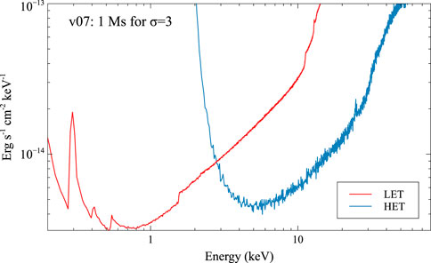
FIGURE 8. The differential flux, dF/dE, of the LET and HET based on the responses for the v07 instrument summarized in Table 1.
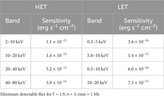
TABLE 2. Sensitivity of the LET and HET.
5 Mission profile
The proposed HEX-P mission baseline is 5 years, with 30% of the observing time dedicated to the PI-led program and 70% to the GO program. The spacecraft carries consumables for 20 years, and in the extended mission phase, 100% of the observing time will be dedicated to the GO program. During the baseline mission, the GO program is executed alongside the PI-led program.
The two instruments, HET and LET, are co-aligned and simultaneously observe the same field to provide the required broadband coverage. At L1, the mission achieves an observing efficiency ≥90%, with the remaining 10% used for overhead, calibration observations, and engineering for slews, desaturation, and station-keeping maneuvers. Solar shields maintain a 60° solar keep-out zone for an instantaneous
The HSC manages the Science Data Center, where all data undergo a quality assurance check before being sent to the High-Energy Astrophysics Science Archive Research Center (HEASARC) at GSFC to be archived and distributed to the community. Within 2 weeks of being taken, all science data are made publicly available without a proprietary period, in compliance with SPD-41a.
The HSC will produce a serendipitous HEX-P Source Catalog, updated annually, to support the use of archival data. This catalog, based on the XMM-Newton Serendipitous Survey (Webb et al., 2020) and the Chandra Source Catalog (Evans et al., 2010), will provide easy access to HEX-P observations with standardized data products.
6 Summary
In summary, the HEX-P payload instrument has been designed to address the astrophysical questions highlighted by the 2020 Decadal Survey on Astronomy and Astrophysics. Instrument responses have been derived using advanced and detailed modeling of the instruments and the background, and they reflect the current best estimate of performance as of Spring 2023. The instrument responses have been made publicly available and in a format for use with XSPEC and SIXTE.
HEX-P will be launched into L1 with an observing efficiency
Author contributions
KM: Conceptualization, Data curation, Formal Analysis, Investigation, Methodology, Project administration, Software, Supervision, Validation, Writing–original draft, Writing–review and editing. JG: Conceptualization, Writing–original draft, Writing–review and editing. DS: Conceptualization, Writing–original draft, Writing–review and editing. RA: Formal Analysis, Investigation, Software, Writing–original draft, Writing–review and editing. SB: Formal Analysis, Investigation, Software, Writing–original draft, Writing–review and editing. DC: Formal Analysis, Investigation, Writing–original draft, Writing–review and editing. BG: Formal Analysis, Investigation, Writing–original draft, Writing–review and editing. SK: Formal Analysis, Investigation, Writing–original draft, Writing–review and editing. AM: Investigation, Writing–original draft, Writing–review and editing. PM: Investigation, Writing–original draft, Writing–review and editing. KN: Writing–original draft, Writing–review and editing. GP: Investigation, Writing–original draft, Writing–review and editing. PP: Writing–original draft, Writing–review and editing. AR: Formal Analysis, Investigation, Writing–original draft, Writing–review and editing. DS: Formal Analysis, Investigation, Software, Writing–original draft, Writing–review and editing. Joern JW: Software, Writing–original draft, Writing–review and editing. WZ: Investigation, Writing–original draft, Writing–review and editing.
Funding
The author(s) declare that no financial support was received for the research, authorship, and/or publication of this article.
Acknowledgments
The work of DS was carried out at the Jet Propulsion Laboratory, California Institute of Technology, under a contract with NASA.
Conflict of interest
The authors declare that the research was conducted in the absence of any commercial or financial relationships that could be construed as a potential conflict of interest.
Publisher’s note
All claims expressed in this article are solely those of the authors and do not necessarily represent those of their affiliated organizations, or those of the publisher, the editors and the reviewers. Any product that may be evaluated in this article, or claim that may be made by its manufacturer, is not guaranteed or endorsed by the publisher.
Footnotes
1https://www.nationalacademies.org/our-work/decadal-survey-on-astronomy-and-astrophysics-2020-astro2020
References
Ayre, M., Bavdaz, M., Ferreira, I., Wille, E., Fransen, S., Stefanescu, A., et al. (2018). “ATHENA: system studies and optics accommodation,”. Space telescopes and instrumentation 2018: ultraviolet to gamma ray. Editors J.-W. A. den Herder, S. Nikzad, and K. Nakazawa (International Society for Optics and Photonics), 10699. doi:10.1117/12.2313305
Basso, S., Pareschi, G., Citterio, O., Spiga, D., Tagliaferri, G., Raimondi, L., et al. (2011). “The optics system of the New Hard X-ray Mission: status report,”. Optics for EUV, X-ray, and gamma-ray Astronomy V. Editors S. L. O’Dell, and G. Pareschi (International Society for Optics and Photonics), 8147. doi:10.1117/12.895324
Bavdaz, M., Wille, E., Ayre, M., Ferreira, I., Shortt, B., Fransen, S., et al. (2021). The athena x-ray optics development and accommodation, 72. doi:10.1117/12.2599341
Brightman, M., Margutti, R., Polzin, A., Jaodand, A., Hotokezaka, K., Alford, J. A. J., et al. (2023). The High Energy X-ray Probe (HEX-P): sensitive broadband X-ray observations of transient phenomena in the 2030s. arXiv:2311.04856. doi:10.48550/arXiv.2311.04856
Chen, C., Cook, W., Harrison, F., Lin, J., Mao, P., and Schindler, S. (2004). Characterization of the heft cdznte pixel detectors. Proc. SPIE 5198. doi:10.1117/12.506075
Cotroneo, V., Pareschi, G., Spiga, D., and Tagliaferri, G. (2009). “Optimization of the reflecting coatings for the new hard x-ray mission,”. Optics for EUV, X-ray, and gamma-ray Astronomy IV. Editors S. L. O’Dell, and G. Pareschi (International Society for Optics and Photonics), 7437. doi:10.1117/12.827347
Dauser, T., Falkner, S., Lorenz, M., Kirsch, C., Peille, P., Cucchetti, E., et al. (2019). Sixte: a generic x-ray instrument simulation toolkit. A&A 630, A66. doi:10.1051/0004-6361/201935978
Eraerds, T., Antonelli, V., Davis, C., Hall, D. J., Hetherington, O., Holland, A. D., et al. (2021). Enhanced simulations on the athena/wide field imager instrumental background. J. Astronomical Telesc. Instrum. Syst. 7, 034001. doi:10.1117/1.JATIS.7.3.034001
Evans, I. N., Primini, F. A., Glotfelty, K. J., Anderson, C. S., Bonaventura, N. R., Chen, J. C., et al. (2010). The chandra source catalog. Astrophysical J. Suppl. Ser. 189, 37–82. doi:10.1088/0067-0049/189/1/37
Harrison, F. A., Craig, W. W., Christensen, F. E., Hailey, C. J., Zhang, , el, al., et al. (2013). The nuclear spectroscopic telescope array (NuSTAR) high-energy X-ray mission. ApJ 770, 103. doi:10.1088/0004-637X/770/2/103
Harvey, J. E., Krywonos, A., Thompson, P. L., and Saha, T. T. (2001). Grazing-incidence hyperboloid–hyperboloid designs for wide-field x-ray imaging applications. Appl. Opt. 40, 136–144. doi:10.1364/AO.40.000136
Herrmann, S., Koch, A., Obergassel, S., Treberspurg, W., Bonholzer, M., and Meidinger, N. (2018). “VERITAS 2.2: a low noise source follower and drain current readout integrated circuit for the wide field imager on the Athena x-ray satellite,”. High energy, optical, and infrared detectors for Astronomy VIII. Editors A. D. Holland, and J. Beletic (International Society for Optics and Photonics), 10709. doi:10.1117/12.2314335
Madsen, K. K., Broadway, D., and Ferreira, D. D. M. (2022). “Single-layer and multilayer coatings for astronomical X-ray mirrors,” in Handbook of X-ray and gamma-ray astrophysics. Editors C. Bambi, and A. Santangelo, 71. doi:10.1007/978-981-16-4544-0_4-1
Madsen, K. K., Christensen, F. E., Jensen, C. P., Ziegler, E., Craig, W. W., Gunderson, K. S., et al. (2004). “X-ray study of W/Si multilayers for the HEFT hard x-ray telescope,”. Optics for EUV, X-ray, and gamma-ray Astronomy. Editors O. Citterio, and S. L. O’Dell (of Proc. SPIE), 5168, 41–52. doi:10.1117/12.505665
Madsen, K. K., Corsetti, J., Kenyon, S., Okajima, T., Rohrback, S., Tamura, K., et al. (2023a). “Mirror design for the high-energy x-ray probe (HEX-P),”. Optics for EUV, X-ray, and gamma-ray Astronomy XI. Editors S. L. O’Dell, J. A. Gaskin, G. Pareschi, and D. Spiga (International Society for Optics and Photonics), 12679, 126791E. doi:10.1117/12.2677554
Madsen, K. K., Fleischhack, H., Violette, D. P., Grefenstette, B. W., Zoglauer, A., Arenberg, J., et al. (2023b). “Background simulations for the high energy x-ray probe (HEX-P),”. UV, X-ray, and gamma-ray space instrumentation for Astronomy XXIII. Editors O. H. Siegmund, and K. Hoadley (International Society for Optics and Photonics), 12678, 126781B. doi:10.1117/12.2676891
Madsen, K. K., Harrison, F. A., Mao, P. H., Christensen, F. E., Jensen, C. P., Brejnholt, N., et al. (2009). “Optimizations of Pt/SiC and W/Si multilayers for the nuclear spectroscopic telescope array,” in Optics for EUV, X-ray, and gamma-ray Astronomy IV (of Proc. SPIE), 7437. doi:10.1117/12.826669
Meidinger, N., Albrecht, S., Beitler, C., Bonholzer, M., Emberger, V., Frank, J., et al. (2020). “Development status of the wide field imager instrument for Athena,”. Space telescopes and instrumentation 2020: ultraviolet to gamma ray. Editors J.-W. A. den Herder, S. Nikzad, and K. Nakazawa (International Society for Optics and Photonics), 11444, 114440T. doi:10.1117/12.2560507
Pareschi, G., Tagliaferri, G., Attinà, P., Basso, S., Borghi, G., Citterio, O., et al. (2009). “Design and development of the optics system for the NHXM hard X-ray and polarimetric mission,”. Optics for EUV, X-ray, and gamma-ray Astronomy IV. Editors S. L. O’Dell, and G. Pareschi (International Society for Optics and Photonics), 7437. doi:10.1117/12.828142
Piotrowska, J. M., García, J. A., Walton, D. J., Beckmann, R. S., Stern, D., Ballantyne, D. R., et al. (2023). “The high energy X-ray probe (HEX-P),” in Constraining supermassive black hole growth with population spin measurements. arXiv:2311.04752. doi:10.48550/arXiv.2311.04752
Riveros, R. E., Allgood, K. D., Biskach, M. P., DeVita, T. A., Hlinka, M., Kearney, J. D., et al. (2022). “Fabrication of lightweight silicon x-ray mirrors,”. Space telescopes and instrumentation 2022: ultraviolet to gamma ray. Editors J.-W. A. den Herder, S. Nikzad, and K. Nakazawa (International Society for Optics and Photonics), 12181. doi:10.1117/12.26290171218111
Saha, T. T., and Zhang, W. W. (2022). Optical design of type-1 x-ray telescopes and their application to star-x. Appl. Opt. 61, 505–516. doi:10.1364/AO.446958
Spiga, D., Raimondi, L., Furuzawa, A., Basso, S., Binda, R., Borghi, G., et al. (2011). “Angular resolution measurements at SPring-8 of a hard x-ray optic for the New Hard X-ray Mission,”. Optics for EUV, X-ray, and gamma-ray Astronomy V. Editors S. L. O’Dell, and G. Pareschi (International Society for Optics and Photonics), 8147. 81470A. doi:10.1117/12.894488
Svendsen, S., Massahi, S., Ferreira, D. D., Gellert, N. C., Jegers, A. S., Christensen, F. E., et al. (2022). “Characterisation of iridium and low-density bilayer coatings for the Athena optics,”. Space telescopes and instrumentation 2022: ultraviolet to gamma ray. Editors J.-W. A. den Herder, S. Nikzad, and K. Nakazawa (International Society for Optics and Photonics), 12181, 121810Z. doi:10.1117/12.2629976
Vernani, D., Bianucci, G., Grisoni, G., Marioni, F., Valsecchi, G., Keereman, A., et al. (2022). “Follow-up x-ray telescope (FXT) mirror module for the Einstein probe mission,”. Space telescopes and instrumentation 2022: ultraviolet to gamma ray. Editors J.-W. A. den Herder, S. Nikzad, and K. Nakazawa, 12181. doi:10.1117/12.2630147
Vernani, D., Borghi, G., Calegari, G., Castelnuovo, M., Citterio, O., Ferrario, I., et al. (2011). “Performance of a mirror shell replicated from a new flight quality mandrel for eROSITA mission,”. Optics for EUV, X-ray, and gamma-ray Astronomy V. Editors S. L. O’Dell, and G. Pareschi (International Society for Optics and Photonics), 8147. doi:10.1117/12.895329
Keywords: X-ray, HEX-P, mission, future concept, instrumentation
Citation: Madsen KK, García JA, Stern D, Amini R, Basso S, Coutinho D, Grefenstette BW, Kenyon S, Moretti A, Morrissey P, Nandra K, Pareschi G, Predehl P, Rau A, Spiga D, Wilms J and Zhang WW (2024) The high energy X-ray probe (HEX-P): instrument and mission profile. Front. Astron. Space Sci. 11:1357834. doi: 10.3389/fspas.2024.1357834
Received: 18 December 2023; Accepted: 30 January 2024;
Published: 01 March 2024.
Edited by:
Renee Ludlam, Wayne State University, United StatesReviewed by:
Herman Marshall, Massachusetts Institute of Technology, United StatesRichard Rothschild, University of California, San Diego, United States
Copyright © 2024 Madsen, García, Stern, Amini, Basso, Coutinho, Grefenstette, Kenyon, Moretti, Morrissey, Nandra, Pareschi, Predehl, Rau, Spiga, Wilms and Zhang. This is an open-access article distributed under the terms of the Creative Commons Attribution License (CC BY). The use, distribution or reproduction in other forums is permitted, provided the original author(s) and the copyright owner(s) are credited and that the original publication in this journal is cited, in accordance with accepted academic practice. No use, distribution or reproduction is permitted which does not comply with these terms.
*Correspondence: Kristin K. Madsen, kristin.c.madsen@nasa.gov