 Changbo Zhu
 Xianguo Zhang1*
- 1Beijing Key Laboratory of Space Environment Exploration, National Space Science Center, Chinese Academy of Sciences, Beijing, China
- 2School of Earth and Space Science and Technology, Wuhan University, Wuhan, China
- 3Key Laboratory of Earth and Planetary Physics, Institute of Geology and Geophysics, Chinese Academy of Sciences, Beijing, China
- 4College of Earth and Planetary Sciences, University of Chinese Academy of Sciences, Beijing, China
The study of the beam envelope radius—a parameter characterizing the transverse size and evolution of a particle beam along its propagation path—is fundamental to the particle accelerators application and the execution of space-borne experiments employing artificial relativistic electron beams. In this paper, we investigate the propagation of electron beams in vacuum and derive an integral form of the beam envelope equation. This equation is equivalent to the simplified differential form of the Kapchinsky-Vladimirsky (K-V) equation excluding the effects of external forces and radial emittance. The integral equation is validated by the widely used ASTRA (A Space Charge Tracking Algorithm) simulation code. The effect of electron energy on beam envelope radius is uncertain and depends on whether internal force or external force dominates. When external force dominates, a decrease in electron energy results in a smaller beam envelope radius. Conversely, when internal force dominates, an increase in electron energy leads to a smaller beam envelope radius. This study is a bridge between integral form and differential form of the envelope equation, and will provide a better understanding for the K-V equation and a scientific basis for researching beam propagation technology.
Key points
• An integral form of the beam envelope equation for electron beam propagation in a vacuum is derived.
• This equation is equivalent to the simplified differential form of the K-V equation excluding the effects of external forces and radial emittance.
• The effect of electron energy on beam radius depends on whether internal or external forces dominate.
1 Introduction
An electron beam is a collection of energetic electrons, typically generated either naturally or artificially (Banks and Raitt, 1988; Winckler, 1980), which are manipulated by electromagnetic fields and directed through a vacuum or plasma (Neubert and Gilchrist, 2002a; Borovsky et al., 2020). Electron beams are found in many space environments, such as the solar wind (Arshad et al., 2014; Sun et al., 2020), magnetic reconnection outflow region (Åsnes et al., 2008), and auroras (Banks and Raitt, 1988), particularly in areas where energetic electrons are accelerated by waves. Electron beams can interact with magnetic fields and background plasma (Druyvesteyn, 1938; Mustafaev, 2001; Arshad and Mirza, 2014; Reeves et al., 2020), playing a significant role in a variety of space phenomena.
Electron beams have proven to be a powerful tool in space science research. During the 1970s and 1980s, keV electron beams were injected from balloons and sounding rockets to probe the fundamental physical processes in space physics. There experiments were used for applications such as mapping magnetic fields lines in the Earth’s magnetosphere [e.g., Hendrickson et al., 1975, 1976; Winckler et al., 1975], exciting artificial auroras, studying beam-plasma interactions [e.g., Gendrin, 1974; Cambou et al., 1978, 1980], and investigating wave generation and amplification as well as instabilities [e.g., Monson et al., 1976; Dechambre et al., 1980]. They also provided insights into spacecraft charging [e.g., Mullen et al., 1986; Sasaki et al., 1986, 1988; Banks et al., 1990], as well as military applications. From the late 1990s to the present, the development of electron accelerator technology (Szuszczewicz, 1985; Lewellen and Buechler, 2019) enabled the injection of relativistic electron beams into the space environment from spacecraft [e.g., Neubert et al., 1996; Krause, 1998, 1999; Gilchrist et al., 2001; Neubert and Gilchrist., 2002b, Neubert and Gilchrist, 2004; Miars et al., 2020; Reeves et al., 2020; Xue et al., 2023; Fang et al., 2024]. Results from these studies indicate that relativistic beams are more stable than keV beams, due to a combination of factors including the higher relativistic electron mass, lower beam densities, and reduced spacecraft charging effects.
In Earth’s auroras, magnetic reconnection generates high-energy electron beams that are accelerated and injected along magnetic field lines into regions such as the ionosphere, forming well-defined beam structures. Electron beams possess high kinetic energy and excellent directional properties, enabling them to interact with spacecraft in orbit and produce space radiation effects, such as surface charging, internal charging, and total ionizing dose effect (Zheng et al., 2019; Bodeau and Baker, 2021). These effects can lead to malfunction in spacecraft, posing significant threats to human spaceflight (Hastings, 1995; Castello et al., 2018). To mitigate or prevent the hazards associated with electron beams, scientists have investigated their generation, propagation, and interaction in the space environment through theoretical analyses and numerical simulations. It is essential for beam envelope control to understand the evolution of electron beam propagation. A critical question in the study of electron beam propagation is identifying the factors that influence the evolution of the electron beam envelope and understanding their quantitative effects.
A significant amount of pioneering work has been conducted to address this question. In 1959, Kapchinsky and Vladimirsky (K-V) made a major breakthrough in beam physics by deriving the envelope equation for a continuous beam with a uniform charge density and an elliptical cross-section (Kapchinsky and Vladimirsky, 1995). This equation accounts for the effects of the self-electric and self-magnetic fields associated with the beam’s space charge and current, as well as external forces. Comparing with the kinetic analysis of single particle, the electron beam tends to diverge owing to space charge forces between two equal-charge particles. Their work became a cornerstone in the field, with profound implications for beam analysis and design. In 1971, Sacherer expanded on this foundation by introducing the concept of root-mean-square (RMS) emittance (Sacherer, 1971). He demonstrated that the K-V equation is not limited to beams with uniform charge density, but is also valid for any charge distribution with elliptical symmetry, provided that the beam boundary and emittance are defined. For convenience, the normalized beam emittance (Lawson, 1988), which represents the product of the beam radius and divergence angle, is used in the K-V equation. The influence of internal forces associated with the beam’s space charge and current remained unclear until the concept of perveance was introduced (Chen and Davidson, 1993), providing a quantitative framework for understanding their role in the K-V equation. When electron beams are injected into plasma instead of a vacuum, the K-V equation must be modified to account for charge neutralization factor (Neubert and Gilchrist, 2002a), as plasma electrons will respond to the beam and move away from it. It is important to note that the K-V equation is a second-order differential equation, and obtaining an analytical expression for the variation of the beam envelope radius with respect to the propagation direction is challenging.
Although K-V equation is a powerful tool for studying the evolution of electron beam envelope, the integral equation is more convenient to describe the variation of the beam envelope radius with respect to the propagation direction. Some theoretical investigations into the integral equation for electron beam propagation have contributed to deriving the expression for perveance in the K-V equation. Bekefi et al. (1980) derived the integral expression for the beam radius at a distance from the source using relativistic particle dynamics. However, their integral expression did not account for the slope of the trajectory at the initial position (Bekefi et al., 1980; Vinokurov, 2001). Reiser added the initial slope to the integral expression, but he overlooked the case in which the slope of the trajectory becomes negative when the beam converges (Reiser, 2008).
Despite the progress made in these studies, further research is still needed on the integral equation governing electron beam propagation. In this paper, we examine the propagation of electron beams in a vacuum and derive an integral form of the beam envelope equation. This equation is equivalent to the simplified differential form of the K-V equation, excluding the effects of external forces and radial emittance. Additionally, we discover that the impact of electron energy on the beam envelope radius is uncertain and depends on whether internal or external forces dominate. The structure of this paper is organized as follows: Section 2 presents the derivation of the integral form of the beam envelope equation and the validation of integral equation by ASTRA simulation code. In Section 3, we provide the relationship between the integral form and the K-V equation. Finally, Section 4 offers a briefly discussion of the conclusions.
2 The electron beam envelope integral equation
This section presents the derivation of the integral form equation and benchmarks the theoretical electron beam envelope models against numerical simulations performed with ASTRA (A Space Charge Tracking Algorithm). In addition, the quantitative impact of several factors on the electron beam envelope radius is provided.
2.1 Derivation of the electron beam envelope integral equation
The following simplifying assumptions have been made in deriving the equations: (1) The electron density is assumed to be uniform within the cylindrical beam and zero outside it; (2) The transverse velocity component of the electrons is assumed to be small compared to the axial velocity, meaning the angle with the axis (slope) is small; (3) The flow is laminar, meaning all beam particles follow trajectories that do not intersect.
Based on the first assumption, the electron beam is treated as a long cylinder with a maximum radius rb and a number density n0. The assumption of uniform charge density results in space-charge forces that are linearly proportional to the distance from the beam’s center. This linear relationship significantly simplifies the equations of motion, making them analytically solvable. Without the assumption of uniform charge density, the charge density ρ(r) varies with radial distance r. This variation alters the calculation of the space charge force. Under the uniform charge density assumption, the radial space charge force
As indicated by the second assumption, the velocity of the electrons in the beam, v, is primarily directed along the axial direction (i.e., vr << v, vθ<<v, vz ≈ v, vr is the radial component of velocity, vθ is the angular component of velocity, and vz is the axial component of velocity.). Thus, the charge density is
The azimuthal component of magnetic field is obtained using Ampère’s circuital law (Cavalleri et al., 1996),
where we neglect the force term
Using the relationship
The perveance K, a dimensionless quantity, is defined by Chen and Davidson (1993) as Equations 8, 9
where
It is important to note that K > 0 for electrons. Multiplying both sides of Equation 10 by
By integrating Equation 11, we get
Evaluating Equation 12 with the initial boundary conditions rb =
Next, we integrate Equation 13 by defining u =
From the expression of u, we have
Substituting Equation 16 into the Equation 15, we obtain
The Dawson integral is given by
using the expression for the Dawson integral. If the initial slope of the beam profile is negative (
where F(w) represents the Dawson integral. When the initial slope of the trajectory is negative (i.e.,
By combining Equations 19, 21, 23, we obtain
The negative sign in Equation 17 applies when
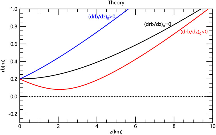 0," a black line with zero slope labeled "(drb/dz)_0 = 0," and a red line with negative slope labeled "(drb/dz)_0 < 0."" id="F1" loading="lazy">
Figure 1. The theorical electron beam envelope radius as a function of propagation distance for three initial slopes of the trajectory (
2.2 Numerical verification of electron beam envelope equations with ASTRA
To compare and validate the theoretical electron beam envelope equations in integral form, the propagation of the electron beam is simulated using the ASTRA code (Floettmann, 2017). ASTRA, a space charge tracking algorithm developed by the German Electron Synchrotron Research Institute (DESY), employs the Particle-In-Cell (PIC) method to simulate collective self-field effects, such as space charge, in high-energy charged particle beams. The program incorporates comprehensive algorithms for generating initial particle distributions and performing particle tracking, making it a widely used tool in simulation studies of high-energy charged particles.
Figure 2 illustrates how ASTRA works. The program generator can be used to generate an initial particle distribution by specifying parameters such as the particle count, particle energy, and types of beam distributions (radial uniform/Gaussian/plateau) in the input file. The core program Astra then performs particle tracking under the influence of internally computed space-charge fields and/or external electromagnetic fields. Its computational workflow iterates through four integrated components: (1) Field Calculation, which solves the governing field equations on a discrete grid; (2) Field Interpolation, which interpolates both external and self-generated fields from the grid nodes to individual particle positions; (3) Particle Push, which integrates the equations of motion over a time step to update particle positions and momenta; and (4) Charge Deposition, which maps particle charges back onto the grid. This cycle repeats until the simulation concludes.
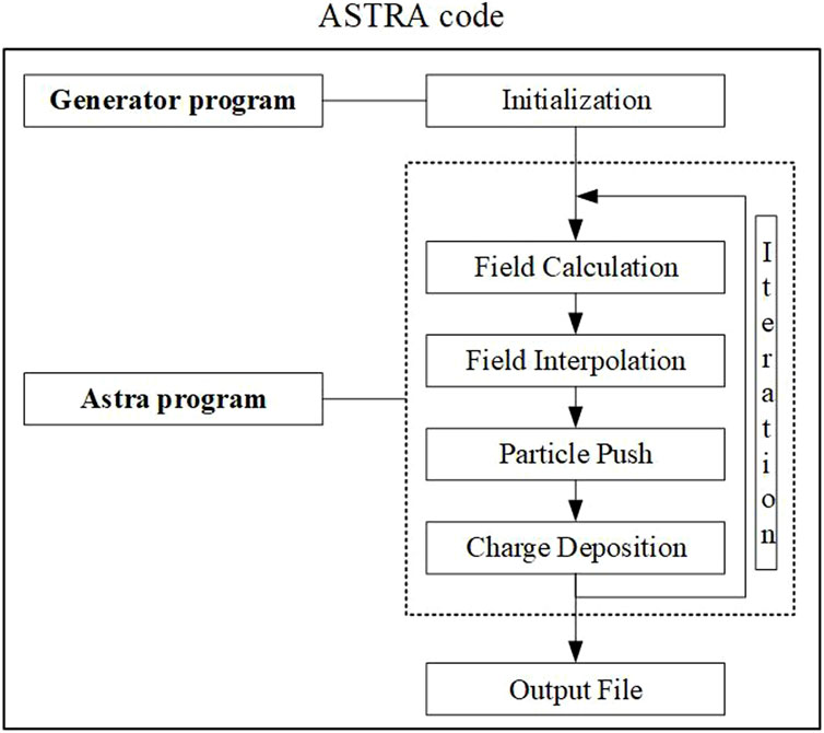
Figure 2. The flow chart of ASTRA code.
In the ASTRA program, the 1 MeV electrons are assumed to be evenly spread out across the cross-sectional area. In a uniform distribution, the maximum radius rb is
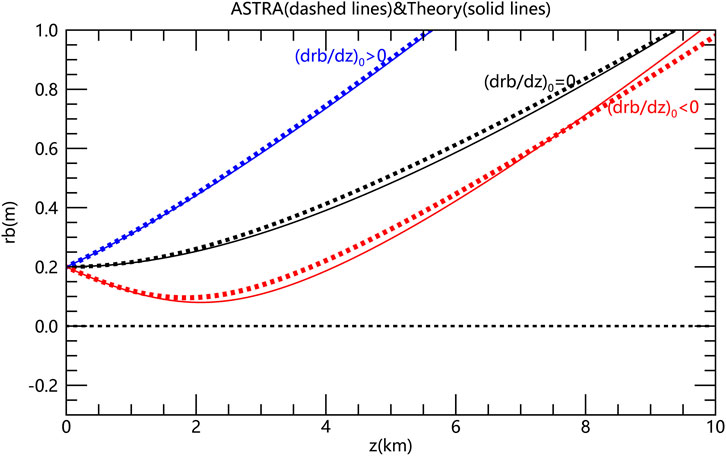
Figure 3. The electron beam envelope radius as a function of propagation distance for three initial slopes of the trajectory (
2.3 Results and discussion
According to Equations 17, 5, the theoretical electron beam envelope radius depends on energy, current and initial beam radius. Figure 4 presents the variation of beam radius with respect to propagation distance for three different energy levels: E = 1 MeV (black curve), E = 2 MeV (blue curve), and E = 4 MeV (red curve). These results were obtained under the following conditions: an initial current of I0 = 1mA, an initial beam radius of
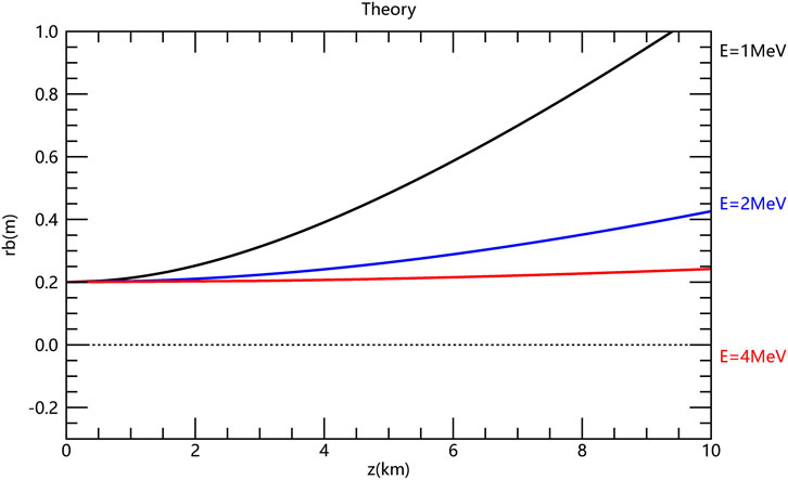
Figure 4. The theorical electron beam envelope radius as a function of propagation distance for three energies (E = 1MeV, E = 2 MeV and E = 4 MeV) with current I0 = 1 mA, initial beam radius
Figure 5 shows how the beam radius changes with propagation distance for three different current values: I0 = 1 mA (black curve), I0 = 5 mA (blue curve), and I0 = 10 mA (red curve), while keeping the energy constant at E = 1 MeV, the initial beam radius at
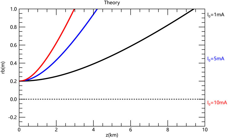
Figure 5. The theorical electron beam envelope radius as a function of propagation distance for three currents (I0 = 1mA, I0 = 5 mA and I0 = 10 mA) with an energy E = 1MeV, initial beam radius
Figure 6 illustrates the effect of varying initial beam radii on the propagation of beam radius with respect to distance. The three cases considered are:
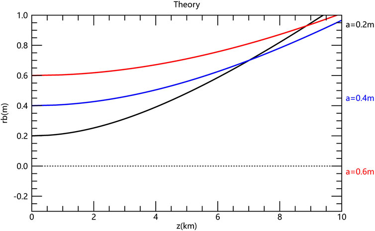
Figure 6. The theorical electron beam envelope radius as a function of propagation distance for three initial beam radii (
3 Relationship between the integral form and K-V equation
The derivative of both sides of the Equation 24 gives
where
The derivative of w with respect to rb is
Substituting Equation 26 and Equation 27 into Equation 25 yields Equation 13. The K-V equation is expressed as
where k0 =
under the conditions of constant k0. If the radial emittance is zero and no external force is applied, Equation 29 simplifies to Equation 13. The integral Equation 24 is equivalent to the simplified differential form of the K-V equation, excluding the effects of external forces and radial emittance. The derivative
It is worth noting that electron energy is included in the expression for both k0 and K. The combined effect of electron energy depends on whether k0 or K dominates. When k0 dominates, a decrease in electron energy results in a smaller beam envelope radius. Conversely, when K dominates, an increase in electron energy leads to a smaller beam envelope radius.
As shown in Figure 7, the four colored curves (purple, cyan, green, and orange) represent the results derived from the K-V equation with a current I0 = 1 mA, an initial beam radius
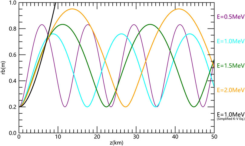
Figure 7. The electron beam envelope radius as a function of propagation distance for energies E = 0.5 MeV (purple curve), E = 1.0 MeV (cyan curve), E = 1.5 MeV (green curve) and E = 2.0 MeV (orange curve), as determined by the K-V equation. The black curve represents the result for E = 1.0MeV, guided by simplified K-V equation without
4 Conclusion
This paper presents a theoretical and analytical framework for studying electron beam transport. The integral equation for the electron beam envelope in a vacuum is derived. This equation accounts for both Coulomb repulsion and self-magnetic forces. Although these two forces act in opposite directions, their combined effect causes the beam to diverge.
The radius of the electron beam envelope is determined by several factors, including the initial beam radius, the initial slope of the trajectory, the magnitude of magnetic field, the current and the electron energy. Specifically, a smaller initial radius leads to a larger beam envelope radius. If the initial slope of the trajectory is greater than or equal to zero, the electron beam will diverge. If the initial slope is negative, the beam will first converge and then diverge. The parameter k0, which quantifies the focusing strength of the applied magnetic field, is proportional to the magnitude of the magnetic field. Thus, a stronger magnetic field causes the electron beam to converge. The perveance K, which quantifies the defocusing effect of the beam’s equilibrium self-fields, is proportional to the current. Therefore, lower current causes the electron beam to converge. The net effect of electron energy on the beam envelope radius is determined by the relative dominance of k0 or K. If k0 dominates, lower electron energy yields a smaller radius; whereas when K dominates, higher electron energy reduces the beam envelope radius.
This study is a bridge between integral form and differential form of the envelope equation, and will provide a better understanding for the K-V equation and a scientific basis for researching beam propagation technology. It is important to note that, in this study, we assume that the background space to be a vacuum environment, while the actual space environment typically includes background plasma. Consequently, future research will focus on the interaction between the electron beam and the background plasma, and how this interaction influences the evolution of the beam envelope radius.
Data availability statement
The datasets presented in this study can be found in online repositories. The names of the repository/repositories and accession number(s) can be found below: https://doi.org/10.6084/m9.figshare.29821676.v1.
Author contributions
CZ: Writing – review and editing, Writing – original draft. XZ: Validation, Writing – review and editing, Investigation. SF: Formal Analysis, Supervision, Writing – review and editing. HZ: Validation, Supervision, Writing – review and editing.
Funding
The author(s) declare that financial support was received for the research and/or publication of this article. This work is supported by Youth Innovation Promotion Association (YIPA) of the Chinese Academy of Sciences (CAS) (E3217A031S), the National Natural Science Foundation of China (42474227), and the China Postdoctoral Science Foundation (E01Z5006).
Conflict of interest
The authors declare that the research was conducted in the absence of any commercial or financial relationships that could be construed as a potential conflict of interest.
Generative AI statement
The author(s) declare that no Generative AI was used in the creation of this manuscript.
Any alternative text (alt text) provided alongside figures in this article has been generated by Frontiers with the support of artificial intelligence and reasonable efforts have been made to ensure accuracy, including review by the authors wherever possible. If you identify any issues, please contact us.
Publisher’s note
All claims expressed in this article are solely those of the authors and do not necessarily represent those of their affiliated organizations, or those of the publisher, the editors and the reviewers. Any product that may be evaluated in this article, or claim that may be made by its manufacturer, is not guaranteed or endorsed by the publisher.
References
Arshad, K., and Mirza, A. M. (2014). Landau damping and kinetic instability in Non-Maxwellian highly electronegative multi-species plasma. Astrophysics Space Sci. 349 (2), 753–763. doi:10.1007/s10509-013-1664-2
Arshad, K., and Poedts, S. (2020). Twisted waves in symmetric and asymmetric bi-ion kappa-distributed plasmas. Phys. Plasmas 27 (12), 122904–122917. doi:10.1063/5.0007380
Arshad, K., Mahmood, S., and Mirza, A. M. (2011). Landau damping of ion acoustic wave in Lorentzian multi-ion plasmas. Phys. Plasmas 18 (9), 092115. doi:10.1063/1.3633237
Arshad, K., Ehsan, Z., Khan, S. A., and Mahmood, S. (2014). Solar wind driven dust acoustic instability with lorentzian kappa distribution. Phys. Plasmas 21 (2), 023704. doi:10.1063/1.4865573
Arshad, K., Lazar, M., Mahmood, S., Aman-ur-Rehman, A. U. R., and Poedts, S. (2017a). Kinetic study of electrostatic twisted waves instability in nonthermal dusty plasmas. Phys. Plasmas 24 (3), 033701. doi:10.1063/1.4977446
Arshad, K., Maneva, Y. G., and Poedts, S. (2017b). Ion acoustic wave damping in a non-Maxwellian bi-ion electron plasma in the presence of dust. Phys. Plasmas 24 (9), 093708. doi:10.1063/1.4995581
Arshad, K., Poedts, S., and Dahshan, A. (2022). Quasi-electrostatic instability in non-gyrotropic tri-ion electron plasma. Aip Adv. 12 (10), 105319. doi:10.1063/5.0014682
Åsnes, A., Taylor, M. G. G. T., Borg, A. L., Lavraud, B., Friedel, R. W. H., Escoubet, C. P., et al. (2008). Multispacecraft observation of electron beam in reconnection region. J. Geophys. Res. Space Phys. 113 (A7). doi:10.1029/2007ja012770
Banks, P. M., and Raitt, W. J. (1988). Observations of electron beam structure in space experiments. J. Geophys. Res. Space Phys. 93 (A6), 5811–5822. doi:10.1029/JA093iA06p05811
Banks, P. M., Gilchrist, B. E., Neubert, T., Myers, N., Raitt, W. J., Williamson, P. R., et al. (1990). Charge-2 rocket observations of vehicle charging and charge neutralization. Adv. Space Res. 10 (7), 133–136. doi:10.1016/0273-1177(90)90286-9
Bekefi, G., Feld, B. T., Parmentola, J., and Tsipis, K. (1980). Particle beam weapons-a technical assessment. Nature 284, 219–225. doi:10.1038/284219a0
Bodeau, M., and Baker, D. N. (2021). Effects of space radiation on contemporary based systems II: spacecraft internal and external charging and discharging effects. Hoboken, NJ, United States: Wiley, Space Weather Effects and Applications, 13–61.
Borovsky, J. E., Delzanno, G. L., and Henderson, M. G. (2020). A mission concept to determine the magnetospheric causes of aurora. Front. Astronomy Space Sci. 7, 595929. doi:10.3389/fspas.2020.595929
Buchholz, D. (1986). Gauss' law and the infraparticle problem. Phys. Lett. B 174 (3), 331–334. doi:10.1016/0370-2693(86)91110-x
Cambou, F., Lavergnat, J., Migulin, V. V., Morozov, A. I., Paton, B. E., Pellat, R., et al. (1978). ARAKS—Controlled or puzzling experiment? Nature 271, 723–726. doi:10.1038/271723a0
Cambou, F., Reme, H., Saint-Marc, A., Lavergnat, J., Dokoukine, V. S., Zhulin, I. A., et al. (1980). General description of the ARAKS experiments. Ann. Geophys. 36, 271–284.
Castello, F. L., Delzanno, G. L., Borovsky, J. E., Miars, G., Leon, O., and Gilchrist, B. E. (2018). Spacecraft-charging mitigation of a high-power electron beam emitted by a magnetospheric spacecraft: simple theoretical model for the transient of the spacecraft potential. J. Geophys. Res. Space Phys. 123 (8), 6424–6442. doi:10.1029/2017JA024926
Cavalleri, G., Spavieri, G., and Spinelli, G. (1996). The ampere and biot-savart force laws. Eur. J. Phys. 17 (4), 205–207. doi:10.1088/0143-0807/17/4/010
Chen, C., and Davidson, R. C. (1993). Properties of the Kapchinskij-Vladimirskij equilibrium and envelope equation for an intense charged-particle beam in a periodic focusing field.
Dechambre, M., Kushnerevsky Yu, V., Lavergnat, J., Pellat, R., Pulinets, S. A., and Selegei, V. V. (1980). Waves observed by the ARAKS experiments: the whistler mode. Ann. Geophys. 36, 341–349.
Druyvesteyn, M. J. (1938). The interaction between an electron beam and a plasma. Physica 5 (7), 561–567. doi:10.1016/s0031-8914(38)80003-3
Fang, M., Liang, Z., Gong, Y., Chen, J., Zhu, G., Liu, T., et al. (2024). Study of the gyro and divergence characteristics of relativistic charged particle beam propagation in Earth’s magnetic field. Adv. High Energy Phys. 2024 (1), 5193401. doi:10.1155/2024/5193401
Floettmann, K. (2017). ASTRA::a space charge tracking algorithm. Available online at: https://www.desy.de/∼mpyflo/.
Gendrin, R. (1974). The French-Soviet ‘ARAKS’ experiment. Space Sci. Rev. 15, 905–931. doi:10.1007/BF00241068
Gilchrist, B. E., Khazanov, G., Krause, L., and Neubert, T. (2001). “Study of relativistic electron beam propagation in the atmosphere-ionosphere-magnetosphere,”. MA: Hanscom AFB. doi:10.21236/ADA402969Tech. Rep, AFRL-VS-TR-2001-1505, Air Force Res. Lab
Hastings, D. E. (1995). A review of plasma interactions with spacecraft in low Earth orbit. J. Geophys. Res. Space Phys. 100 (A8), 14457–14483. doi:10.1029/94JA03358
Hendrickson, R. A., McEntire, R. W., and Winckler, J. R. (1975). Echo I: an experimental analysis of local effects and conjugate return echoes from an electron beam injected into the magnetosphere by a sounding rocket. Planet. Space Sci. 23, 1431–1444. doi:10.1016/0032-0633(75)90039-2
Hendrickson, R. A., Winckler, J. R., and Arnoldy, R. L. (1976). Echo III: the study of electric and magnetic fields with conjugate echoes from artificial electron beams injected into the auroral zone ionosphere. Geophys. Res. Lett. 3, 409–412. doi:10.1029/GL003i007p00409
Jiao, L., Ge, Y., Zhang, Y., Guo, Y., Feng, M., and Fu, S. (2022). Transverse confinement and periodic oscillations of electron beam structures traveling in the Earth′ s magnetic field. Chin. J. Geophys. 65 (10), 3691–3703. doi:10.6038/cjg2022Q0065
Kapchinskij, I. M., and Vladimirskij, V. V. (1959). “Limitations of proton beam current in a strong focusing linear accelerator associated with the beam space charge,” in Proceedings of the international conference on high energy accelerators and instrumentation (CERN Scientific Information Service), 274–288.
Krause, L. H. (1998). The interaction of relativistic electron beams with the near-Earth space environment. Ann Arbor, Mich: Univ. of Michigan. PhD thesis.
Krause, L. H., Neubert, T., and Gilchrist, B. (1999). “Passive remote sensing of artificial relativistic electron beams in the middle atmosphere,” in Proceedings of space technology.
Lewellen, J. W., Buechler, C. E., Carlsten, B. E., Dale, G. E., Holloway, M. A., Patrick, D. E., et al. (2019). Space-borne electron accelerator design. Front. Astron. Space Sci. 6, 35. doi:10.3389/fspas.2019.00035
Miars, G., Delzanno, G. L., Gilchrist, B. E., and Leon, O. (2020). New electron beam experiments in space and active spacecraft potential control. AGU Fall Meet. Abstr. 2020, SM016–SM018.
Monson, S. J., Kellogg, P. J., and Cartwright, D. G. (1976). Whistler mode plasma waves observed on electron Echo 2. J. Geophys. Res. 81, 2193–2199. doi:10.1029/JA081i013p02193
Mullen, E. G., Gussenhoven, M. S., Hardy, D. A., Aggson, T. A., Ledley, B. G., and Whipple, E. (1986). SCATHA survey of high-level spacecraft charging in sunlight. J. Geophys. Res. 91, 1474–1490. doi:10.1029/JA091iA02p01474
Mustafaev, A. S. (2001). Dynamics of electron beams in plasmas. Tech. Phys. 46 (4), 472–483. doi:10.1134/1.1365475
Neubert, T., and Gilchrist, B. E. (2002a). Particle simulations of relativistic electron beam injection from spacecraft. J. Geophys. Res. 107 (A8), 1167. doi:10.1029/2001JA900102
Neubert, T., and Gilchrist, B. (2002b). 3D electromagnetic PIC simulations of relativistic electron pulse injections from spacecraft. Adv. Space. Res. 29 (9), 1385–1390. doi:10.1016/s0273-1177(02)00185-0
Neubert, T., and Gilchrist, B. E. (2004). Relativistic electron beam injection from spacecraft: performance and applications. Adv. Space Res. 34 (11), 2409–2412. doi:10.1016/j.asr.2003.08.081
Neubert, T., Gilchrist, B., Wilderman, S., Habash, L., and Wang, H. J. (1996). Relativistic electron beam propagation in the Earth’s atmosphere: modeling results. Geophys. Res. Lett. 23 (9), 1009–1012. doi:10.1029/96gl00247
Reeves, G. D., Delzanno, G. L., Fernandes, P. A., Yakymenko, K., Carlsten, B. E., Lewellen, J. W., et al. (2020). The beam plasma interactions experiment: an active experiment using pulsed electron beams. Front. Astron. Space Sci. 7, 23. doi:10.3389/fspas.2020.00023
Sacherer, F. J. (1971). RMS envelope equations with space charge. IEEE Trans. Nucl. Sci. 18 (3), 1105–1107. doi:10.1109/tns.1971.4326293
Sasaki, S., Kawashima, N., Kuriki, K., Yanagisawa, M., and Obayashi, T. (1986). Vehicle charging observed in SEPAC Spacelab-1 experiment. J. Spacecr. Rockets 23, 194–199. doi:10.2514/3.25801
Sasaki, S., Oyama, K. I., Kawashima, N., Obayashi, T., Hirao, K., Raitt, W. J., et al. (1988). Tethered rocket experiment (CHARGE-2) initial results on electrodynamics. Radio Sci. 23, 975–988. doi:10.1029/RS023i006p00975
Sun, H., Zhao, J., Liu, W., Xie, H., and Wu, D. (2020). Electron temperature anisotropy and electron beam constraints from electron kinetic instabilities in the solar wind. Astrophysical J. 902 (1), 59. doi:10.3847/1538-4357/abb3ca
Szuszczewicz, E. P. (1985). Controlled electron beam experiments in space and supporting laboratory experiments: a review. J. Atmos. Terr. Phys. 47 (12), 1189–1210. doi:10.1016/0021-9169(85)90088-1
Vinokurov, N. A. (2001). “Space charge,” in AIP conference proceedings (Melville, New York: American Institute of Physics), 390–404.
Winckler, J. R. (1980). The application of artificial electron beams to magnetospheric research. Rev. Geophys. 18 (3), 659–682. doi:10.1029/rg018i003p00659
Winckler, J. R., Arnoldy, R. L., and Hendrickson, R. A. (1975). Echo 2: a study of electron beams injected into the high-latitude ionosphere from a large sounding rocket. J. Geophys. Res. 80, 2083–2088. doi:10.1029/JA080i016p02083
Xue, B., Zhao, Q., Zhang, F., Dong, Z., Hao, J., Fan, J., et al. (2023). Fast spacecraft charging induced by a high-power electron beam emission and its mitigation through a plasma contactor. J. Instrum. 18 (10), P10037. doi:10.1088/1748-0221/18/10/p10037
Keywords: electron beam, beam envelope equation, K-V equation, electron energy, beam radius
Citation: Zhu C, Zhang X, Fu S and Zhang H (2025) Integral form of the beam envelope equation for electron beam propagation in vacuum and its relation to the K-V equation. Front. Astron. Space Sci. 12:1679770. doi: 10.3389/fspas.2025.1679770
Received: 05 August 2025; Accepted: 01 October 2025;
Published: 30 October 2025.
Edited by:
Anna Giribono, National Laboratory of Frascati (INFN), ItalyReviewed by:
Kashif Arshad, The University of Iowa, United StatesBixi Xue, Institute of Applied Physics and Computational Mathematics (IAPCM), China
Copyright © 2025 Zhu, Zhang, Fu and Zhang. This is an open-access article distributed under the terms of the Creative Commons Attribution License (CC BY). The use, distribution or reproduction in other forums is permitted, provided the original author(s) and the copyright owner(s) are credited and that the original publication in this journal is cited, in accordance with accepted academic practice. No use, distribution or reproduction is permitted which does not comply with these terms.
*Correspondence: Xianguo Zhang, emhhbmd4Z0Buc3NjLmFjLmNu