A design approach for thermal enhancement in heat sinks using different types of fins: A review
 Abhijeet Gaikwad
  Anilkumar Sathe
- Mechanical Engineering Department, MIT Art, Design and Technology University, Pune, India
This article provides an in-depth overview of thermal heat sink design and optimization. Heat transfer enhancement strategies are discussed in detail, followed by fin design trends and geometries, and a discussion on different fin configurations and their merits is also presented. Important results and findings of experiments concerning the design and optimization of fin geometries have been summarized. For complex heat dissipation applications, researchers have been studying different fin arrangements especially, inclined fins, to maximize the performance of the heat sinks. Along with innovative fin designs, microchannels for heat dissipation are gaining attention due to their. Recent advances in this domain have been discussed. New components are becoming more compact and advanced as a result of technological breakthroughs in electronics and control systems; hence, the use and optimization of heat sinks for modern applications are also discussed in this article.
1 Introduction
The primary purpose of this research is to examine heat transfer improvement techniques and the effects of various fin shapes on the heat dissipation characteristics of the heat sink. The most common type of heat exchangers used to cool electronic devices is heat sinks. Heat sinks are among the most explored issues in the field of thermal engineering (Khattak and Ali, 2019) due to their simple design, low cost, and broad potential reach. Researchers can now quantify complex data relevant to small electronic frameworks because of advances in processing capabilities and the availability of advanced analysis tools (Yu et al., 2005). Because of poor thermal management, electronic equipment is prone to failure owing to increased heat. The probability distribution of several factors that cause failure in electronic equipment is depicted in Figure 1. Thermal fatigue is the leading cause of equipment failure, accounting for more than 40% of all failures. As a result, heat removal is crucial to ensuring the component’s long-term durability (Ahmed et al., 2018). Researchers have looked into two sorts of heat sink enhancement techniques: active and passive heat sinks. In the next sections, we’ll go through these strategies in detail. Fins are the most fundamental heat sink components, consisting of extended surfaces constructed of high thermal conductivity materials (Yadav et al., 2017). The design of these fins has a significant impact on the heat sink’s overall heat transfer rate. Many parameters, such as fin spacing, fin height, and fin shapes, play a significant part in achieving effective heat dissipation. The most prevalent cooling method is natural convection, with air-cooling being the most traditional. It is also undeniable that heat dissipation is dependent on fluid flow; as a result, researchers should thoroughly investigate and consider the ramifications of diverse flow patterns (Ansari and Kim, 2018). As a result, the cooling system must be appropriately constructed, taking into account all necessary characteristics. Different concepts and designs can be used to create heat sinks. Heat sinks can be created in a variety of ways using the concepts of conduction, convection, and radiation. It is important to realize that these three phenomena are intertwined, which makes the design process more difficult. The cooling system’s primary goal is to keep the component at an optimal temperature at all times in order to maximize its functionality. The selection of proper geometries is critical for facilitating the heat dissipation process. Selecting an acceptable geometry when considering geographical or unique limitations necessitates both computational and numerical analysis [(Ejlali et al., 2009; Farsad et al., 2011; Huang et al., 2015; Balan et al., 2017; Ishak et al., 2019; Ndlovu and Moitsheki, 2019; Jeong et al., 2020; Zhang et al., 2020)]. These optimization strategies, as well as the design’s compactness, are critical in today’s current applications. Various applications are thoroughly examined, as is the utilization of heat dissipation strategies in these applications.
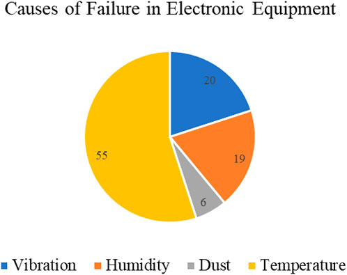
FIGURE 1. Causes of failure in electronic equipment (Khattak and Ali, 2019).
The present review article summarise the research work performed on the thermal heat sink design and its optimization. Different heat transfer enhancement techniques are thoroughly discussed in this article followed by methodology opted in fin design, geometrical modifications and different fin configurations used along with their merits and limitations. Some of the important finidngs and results of the experiments concerning the design and optimisation of the fin geometries have been summarised in the respective sections.
2 Heat transfer enhancement techniques
Heat transfer enhancement techniques are an interesting topic that has received much attention from researchers. New techniques that enhance the heat transfer process must be effective as well as energy-efficient. Improvement in the convective heat transfer rate is often linked to the increase in pressure drop, which implicates high power requirement. This is an important consideration that researchers need to make while designing modern heat transfer enhancement techniques. Conventional heat transfer enhancement techniques include the implementation of extended surfaces or fins, forced flow overheated surfaces, and swirl flow devices to alter the flow fields of the fluid. Nano fluid bionic heat sink is one of the efficient heat transfer enhancement techniques which consists of mixture of nanoparticles and conventional base fluids (Tang et al., 2021). Bionic heat sinks are based on the principle of bionics which relates to structures and processes imitating nature’s mode of organisation, optimization and ad-aptation. This helps to maximise the heat transfer rate and improve performance compared to regular working fluids. Numerous in-depth studies have been conducted due to the low thermal resistance and high thermal conductivity of nanofluids (Qi et al., 2021). Heat transfer enhancement methods are classified into two major types, namely active and passive. The active methods require external power. Passive methods do not need any external power and rely on extended surfaces or components to alter the flow of cooling fluid, which enhances the heat transfer process.
2.1 A. Active techniques
Active heat transfer enhancement techniques use external power to enhance the heat dissipation process. Several modern techniques such as rotating surfaces or elements, introducing vibrations, employing electromagnetic fields, fluid injection and fluid suction. The electromagnetic field method is a recent technique developed to achieve greater heat dissipation. In this method, electrostatic fields can be directed to cause greater bulk fluid mixing in the vicinity of heat transfer surfaces (Hu et al., 2015). Various studies have mentioned that, although the heat transfer rate is significantly enhanced with the help of induced vibration, it may lead to cause an adverse effect such as fatigue stress on the heat sink surface (Bash et al., 2018). Injection and suction techniques are quite common, which includes injecting fluid in the heat sink environment to obtain aggravated and uniform heat distribution in the former and includes pumping out hot air from the heat sink environment to enhance the heat dissipation. These techniques are pretty effective, but a lot of research has been conducted in this field.
2.2 B. Passive techniques
Passive heat transfer techniques do not make use of external energy to enhance the heat transfer process (Khattak and Ali, 2019). These include treating the surfaces of the heat sink components to enhance the heat transfer process, use of extended surfaces or fins, displacement enhancement techniques, swirl flow devices and additives in the fluids. Introducing fins is one of the most common passive techniques. The method involves the extension of the surface, and examples of this method that are being used in practice are micro-fin tubes. Displacement enhancement devices are inserted into the flow channel so as to improve the energy transport indirectly at the heated surface (Park et al., 2015). Swirl flow devices create a rotating flow a secondary flow which enhances the heat dissipation process (Alam and Kim, 2017). Additives for liquids include solid particles and gas particles in single-phase flow, while for gas additives, liquid droplets or solid particles are used (Mokhtari et al., 2017).
3 Fin geometries and arrangements
Researchers are in search of the most effective fin geometry for a particular application. Various fin geometries and arrangements can be effective for an application. Fins can be pin-type or plate type, and they can also have different shapes like circular, rectangular, trapezoidal or hydrofoil (Hu et al., 2015)—(Alam and Kim, 2017), (Keshavarz et al., 2019). The selection of the arrangement of these fins to achieve maximum heat transfer efficiency is another important task of a researcher. Some of the geomtries and fin arrangements are shown in Figure 2 given below.
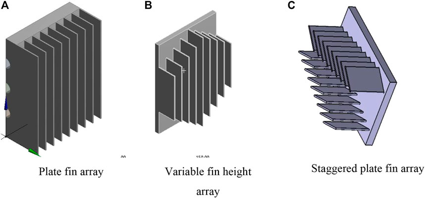
FIGURE 2. Different arrangement of fin geometries. (A) Plate fin array. (B) Variable fin height array. (C) Staggered plate fin array.
Mokhtari et al, (2017) present a study in which models with different pin geometries are developed to analyze the thermal dissipation and fluid flow properties. Here, four geometries, as shown in Figure 3, are analyzed. These models are simple, inclined with the identical pattern, inclined with V-pattern and inclined with the alternate pattern.
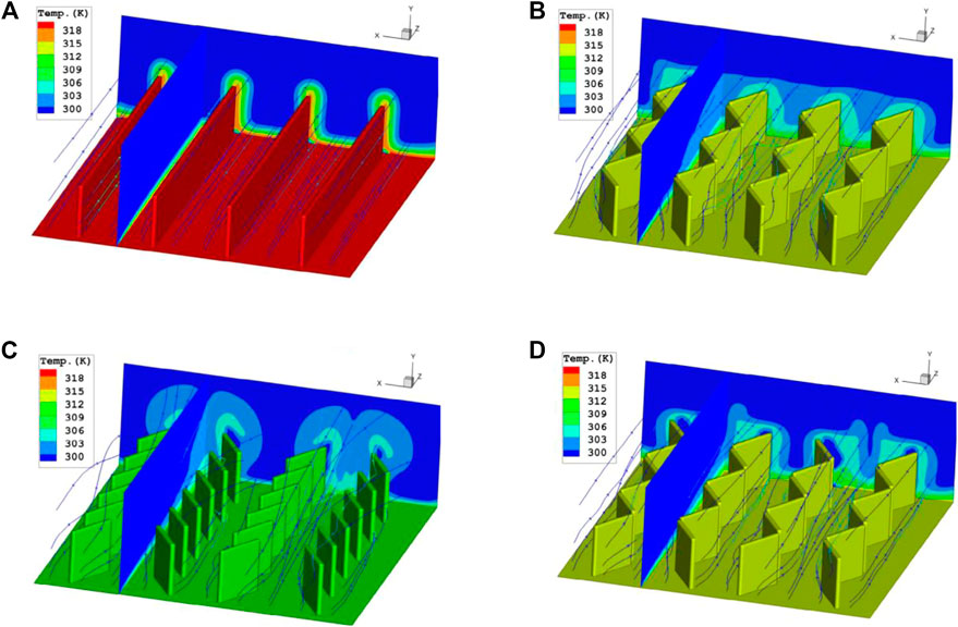
FIGURE 3. Flow stream and temperature distribution on (A) Simple; (B) Model one; (C) Model two; (D) Model 3 (Park et al., 2015).
The analysis observed that the heat transfer improves drastically in the case of the inclined fin arrangement compared to the simple fin arrangement. It is evident from Figure 3 that the inclined fins with V-type arrangement or Model two are the most effective geometry in terms of enhancing the heat transfer rate for both laminar and turbulent flows. Figure 4 shows the temperature distribution for the fin models with limited heat flux. It is visible that Models two and three very effective when it comes to cooling. The article also discusses the presence of an enhanced cooling zone when the fin arrangement is optimized based on the location of the heat flux source on the base plate.
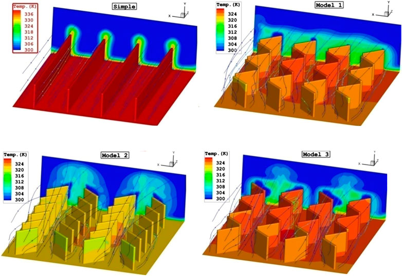
FIGURE 4. Comparisons of temperature distribution for various fin arrangements on the base plate with limited heat flux (Park et al., 2015).
Keshavarz et al, (2019) presented a numerical study comparing an inline circular geometry as a reference with a drop-shaped fin geometry. It was observed that the pumping power required for the drop-shaped geometry was 6.9% less than that required for the reference geometry. Comparison based on fin density was also made. Surprisingly, the inline geometry showed better thermal efficiency than the staggered geometry.
Soodphakdee et al, (2001) studied the heat transfer performance of various commonly used fin geometries. Figure 5 shows the fin geometries, which includes circular, square and parallel plates which are arranged in inline and staggered patterns. It was observed that the staggered arrangements were better in terms of heat transfer than the inline arrangements. Staggered Elliptical fin arrangement was the best performing design for low-pressure drop and pumping power. At higher values, round pin fins offer the highest performance. Figure 6 shows the heat transfer coefficient vs pressure drop plot where it is clearly evident that staggered circular provides better heat transfer coefficient and larger pressure drops.
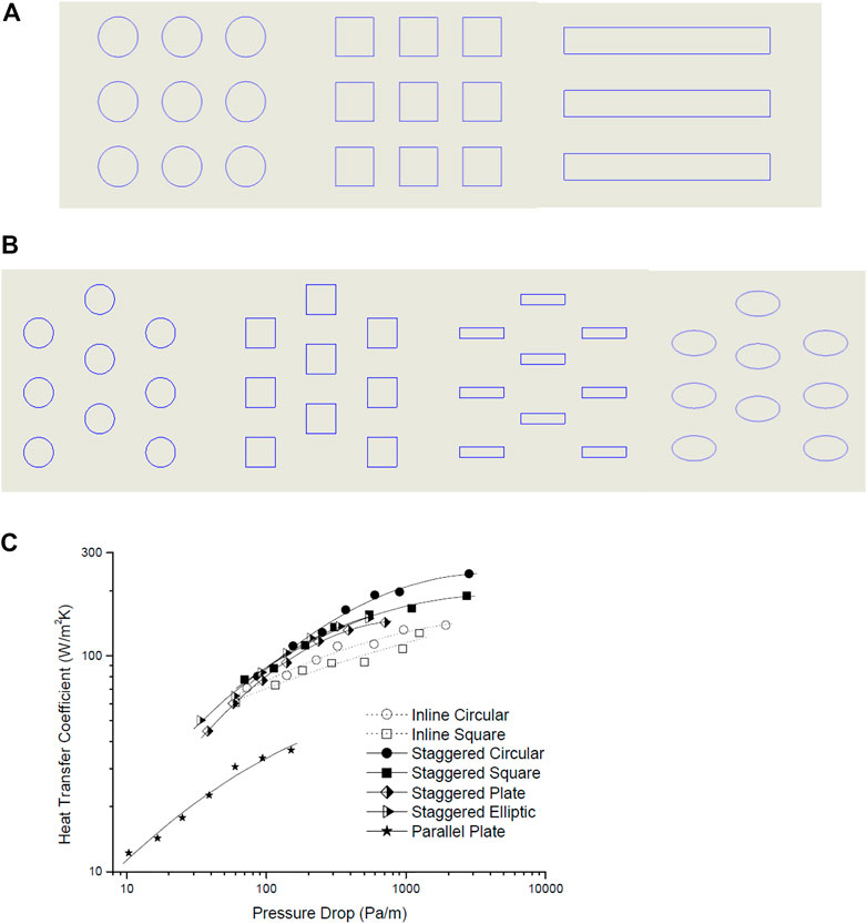
FIGURE 5. (A) i Inline Circular; ii. Inline Square Geometries; iii. Parallel Plates (Mokhtari et al., 2017). (B) I. Staggered Circular; ii. Staggered Square; iii. Staggered Plate iv. Staggered Elliptical (Soodphakdee et al., 2001). (C) Variation of pressure drop versus heat transfer coefficient (Soodphakdee et al., 2001).
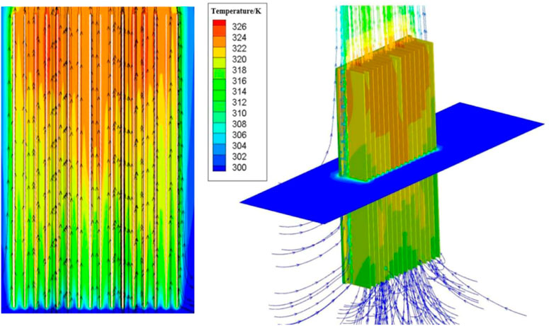
FIGURE 6. The flow lines and temperature distribution of the parallel-plate finned heat sinks (Zhang et al., 2020).
Haghighi et al, (2018) performed experimental analysis to measure the convective heat transfer coefficient and thermal performance of plate fins and plate cubic pin-fins heat sinks for natural convection. The analysis was performed for Rayleigh numbers from 8–106 to 9.5–106 with input heat of 10–120 W. The fin spacing and fin numbers are varied between 5 and 12 mm and five to nine, respectively. It was observed that cubic pin-fin geometry had a higher heat transfer of about 41.6% and lowered thermal resistance when compared to normal plate-fin geometry. It was also observed that the thermal resistance was inversely linked with the fin spaces, and the number of fins had no relation to improvement in heat transfer. Researchers concluded that the best heat sink design had 7–8.5 mm spacing.
4 Perforated fins
Perforated fins are one of the less researched types of the heat sink, which have a huge potential (Huang et al., 2015). Perforated fins are fins with holes or cavities, which are known to improve the heat transfer performance of the heat sinks. The merits of using perforated fins and various studies conducted by researchers on perforated fins are discussed below (Huang et al., 2015). Khattak et al. (Khattak and Ali, 2019) present an extensive review of the air-cooled heat sink geometries. The key findings mentioned in this article are the superiority of perforated fins over inline and staggered geometries in terms of heat transfer rate and pumping power, the better thermal efficiency of circular pin fin geometries compared to square fin geometries for low Re at low pitches and the appreciable feasibility and effectivity of Phase Change Materials (PCM) especially n-eicosane. This study also delineates the effects of the introduction of vortex flow initiators in the heat sinks to enhance heat transfer rates and also opines that additional research is required to study the effects of by-pass flow regimes on the thermal performance of modern pin fin geometries.
5 Inclined fins
Inclined fins are an effective alternative to straight fins due to various merits which impact the heat transfer efficiency of the overall heat sink (Soodphakdee et al., 2001; Sathe and Dhoble, 2019). Also, this inclined fin arrangement is beneficial for achieving less pressure drop. An intensive review is presented on this topic which discusses different heat sink designs using inclined fins. Zhang et al. (Zhang et al., 2020) have studied the heat transfer mechanism of the W-typed heat sink. They have experimentally as well as numerically shown that the cooling effect of W-type heat sink is better than that of parallel plate fins. Figure 6 shows the flow behaviour and temperature distribution in a parallel plate-fin heat sink. On the other hand, Figure 7 depicts the flow behaviour and the temperature distribution in a W-type heat sink. It is evident that on comparing these two figures, the temperature distribution in the W-type heat sink is more uniform and is hence, better at dissipating heat than the parallel plate heat sink. Experimental studies show that specific inclination angles are optimum for a specific fin height model for increased efficiency. This paper also elucidates the effect of gap clearance on pressure drop, and it is also mentioned that in a specific optimum gap range, heat dissipation is maximum due to the suction effect. Finally, a correlation is devised for numerical analysis.
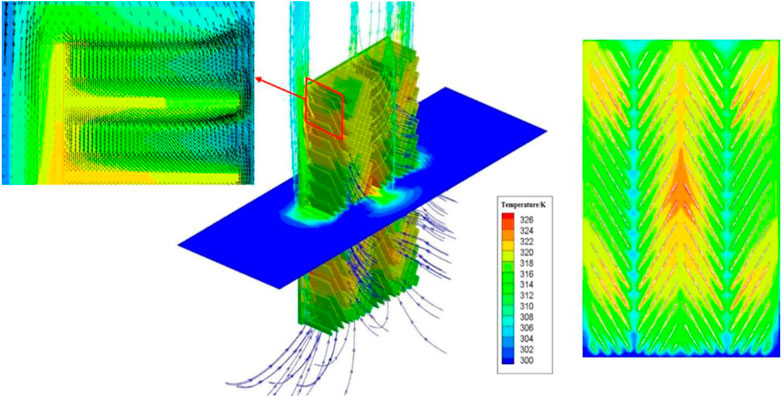
FIGURE 7. The flow lines and temperature distribution of the W-shaped heat sinks (Zhang et al., 2020).
It was observed that upon implementing the W-type finned geometry in the heat sink, the maximum temperature dropped by 4.6°C, and the average temperature dropped by 2.9°C in comparison to the parallel plate finned heat sink. Figure 8. Shows the relationship between the inclination angle and the temperature and the heat transfer coefficient. It is interesting to note that the dissipation area in the W-type fins was 10% less than that of parallel plate fins. Park and Lee, 2017; Sahoo et al., 2018)] studied the effectiveness of an inclined cross-cut cylindrical heat sink for LED bulbs. They summarized that by varying the operating angles, the thermal efficiency could be improved. Figure 9 shows the flow pathlines around the cylindrical heat sink for various inclination angles. At 25°–30° inclination, the thermal resistance was the smallest, and beyond 50°, the thermal performance declined drastically. A correlation was formulated to predict the degree of improvement in the cooling performance relative to a straight cross-cut heat sink as a function of the heat sink design variables and the installation angle of the heat sink. Table 1 provides the summery of research work carried out on fin geometries and effect of heat sink orientation on thermal performance. Table 2 shows the summery of research work on inclined fin geometries.
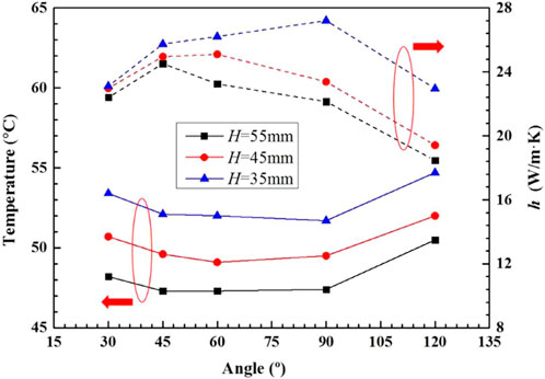
FIGURE 8. The relation of fin inclination angle and heat transfer performance for the W- type heat sinks with fin spacing of 8 mm and fin gap of 8 mm (Zhang et al., 2020).
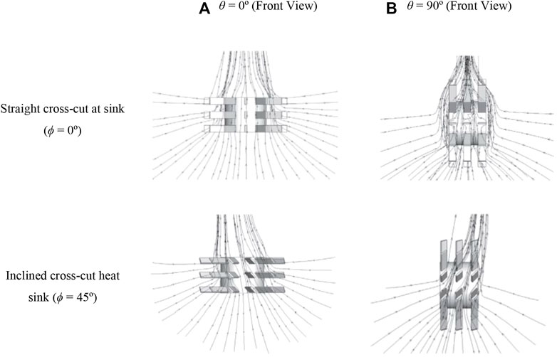
FIGURE 9. Fluid flow lines around a cylindrical heat sink for various installation angles (Q = 5000W/m2, T1 = 26°C). (A) θ = 0° (Front View). (B) θ = 90° (Front View). Straight cross-cut at sink (ϕ = 0°). Inclined cross-cut heat sink (ϕ = 45°) (Park and Lee, 2017).
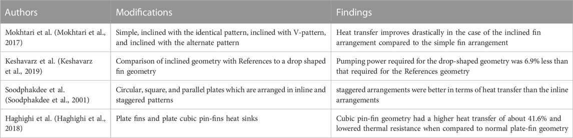
TABLE 1. Summary of work on fin geometris and arrangements.
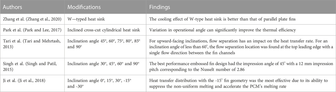
TABLE 2. Summary of work on inclined fin geometry.
Figure 10 shows the plot of Thermal resistance and inclination angle. When the fins had an inclined angle of 25°–30°, the thermal resistance was the smallest. Thermal resistance is represented as, “the ratio of temperature difference between two given points to the heat flow between the two points” which implies increase in thermal resistance hurdles the rate of heat conductio and vice versa. Tari and Mehrtash, 2013) studied the effects of inclination angle on the heat dissipation characteristics of the fins.
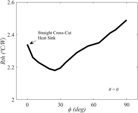
FIGURE 10. Effect of the inclined fin angle (RTH: Thermal Resistance) (Park and Lee, 2017).
Researchers observed that convective heat transfer stayed almost the same for small upward inclination angles. Figure 11 shows streamlines for different inclination angles. At larger angles, the phenomenon is investigated to determine the flow structures forming around the heat sink. The validity of the vertical case correlations for the inclination angles was studied by modifying the Grash off number with the cosine of the inclination angle. Figure 12 shows the relation between surface average temperature, convective heat transfer and radiative heat transfer with different inclination angles. Researchers concluded that for upward-facing inclinations, flow separation has an impact on the heat transfer rate. For an inclination angle of less than 60°, the flow separation location was found at the top leading edge with a single flow direction between the fin channels. Singh and Patil, 2015) also studied the effect of inclination angles of embossed fins on the thermal dissipation properties. Figure 13 shows the fin geometry of the embossed fins.
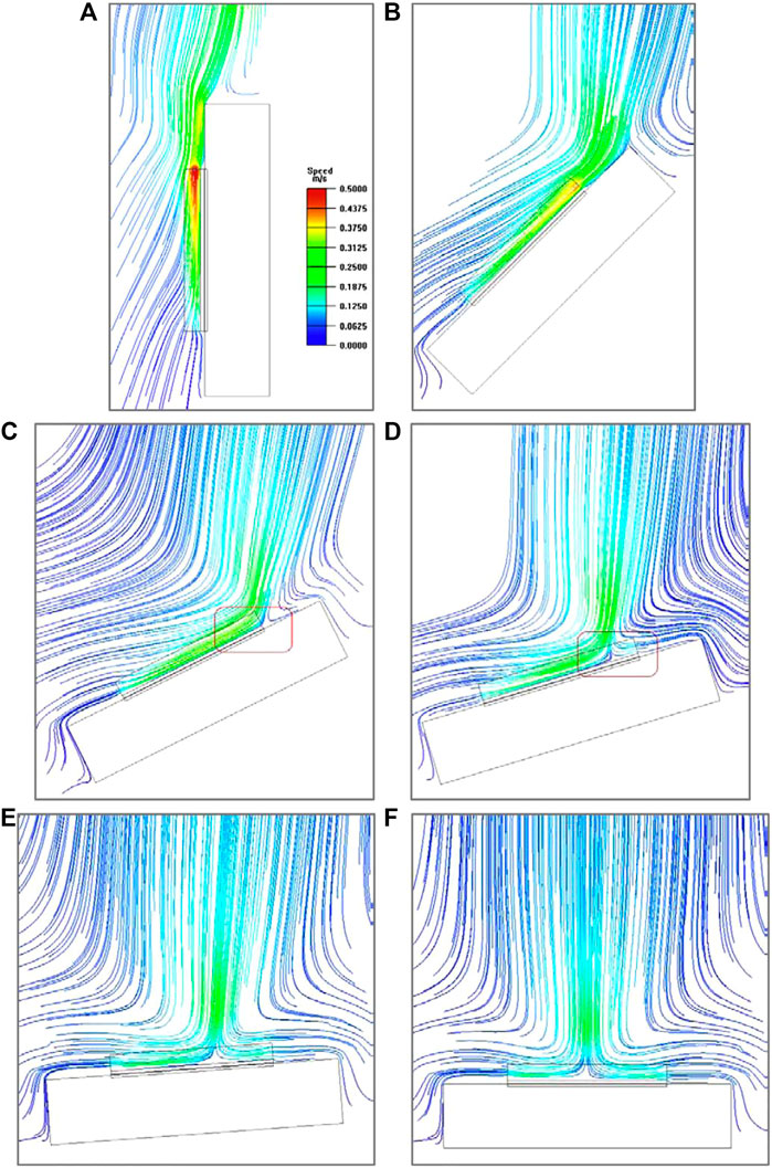
FIGURE 11. Streamlines for (A) the vertical and downward inclined heat sinks at (B) 45, (C) 60, (D) 75, (E) 80, (F) 85 and (g) 90° for Qin = 75W and H = 25 mm with red boxes highlighting flow separation (Tari and Mehrtash, 2013).
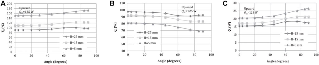
FIGURE 12. Relation between (A). Average surface temperature; (B). Convective Heat Transfer Rate; (C). Radiative Heat Transfer Rate and inclination angle for H = 15, 20 25 mm and Qin = 125 W for upward inclinations (Tari and Mehrtash, 2013).
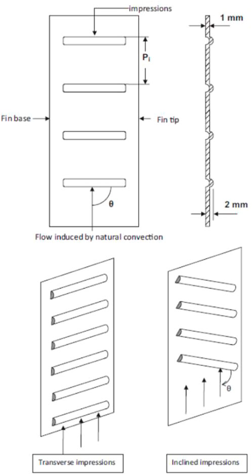
FIGURE 13. Fin geometry (Singh and Patil, 2015).
Researchers used the Nusselt number enhancement ratio and embossed fin effectiveness as parameters to compare the heat transfer performance of embossed fin heat sinks for impression angles from 30° to 90°. Figure 14 shows the embossed fin effectiveness and its relation with heat supplied for different values of impression angles at a fin pitch of 12 mm. The best performance embossed fin design had the impression angle of 45° with a 12 mm impression pitch corresponding to the Nusselt number of 2.86. Ji et al, (2018) present numerical investigations on a thermal energy storage system with phase change materials (PCMs) vertically heated from one side of a rectangular enclosure. Figure 15 shows the contours of melt fraction with natural convection-driven flow vectors for the fin PSM cases with different inclination angles.
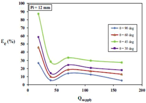
FIGURE 14. Embossed fin effectiveness as a function of heat supplied for different values of impression angles at Pi (Fin Pitch) = 12 mm (Singh and Patil, 2015).
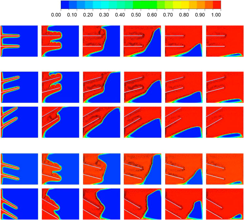
FIGURE 15. Contours of the melt fraction with natural convection driven flow vectors for the fin-PCM cases: (A) θ = 0°; (B) θ = 15°; (C) θ = 30°; (D) θ = 15° and (E) θ = 30°, with the fixed dimensionless fin length l/L = 0.50 and heat flux input qn = 2500 W/m2 (Ji et al., 2018).
Due to the natural convection effect, researchers observed non-uniform heat transfer in the PCMs with no fin array, which can be tracked to the PCM overheating at the top side and reduction in the overall melting rate. Figure 16 shows the temperature contour lines in the PCM domain at t = 10,000 s. The temperature inside the PCM domain was very uniform in other fin cases except for the 0° fin case. Researchers observed that the heat transfer distribution with the -15° fin geometry was the most effective due to its ability to suppress the non-uniform melting and accelerate the PCM’s melting rate. The melting time saved improved 62.7% compared with the identical length fins in 0 deg. Figure 17 shows the temperature contour lines at 0 deg and 15 deg inclination with different length/separation ratios. The fins with −15° performed exceptionally when heat flux input was comparatively lower. González Gallero et al, (2018) have designed a one finned heat sink prototype with high fin height and variable fin thickness. This study focuses on the CFD simulations and experimental data to study the correlations that are commonly used. Heat sink efficiency was tested for varying inclinations, and stagnation areas disappeared in the models where inclination angles were more than 30 deg. Researchers also state the need for future research in this domain.
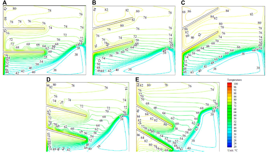
FIGURE 16. Temperature contours lines in the PCM domain at t = 10,000 s: (A) θ = 0°; (B) θ = 15°; (C) θ = 30°; (D) θ =−15° and (E) θ =−30°, with the fixed dimensionless fin length l/L = 0.5 and heat flux input qn = 2500W/m2 (Ji et al., 2018).
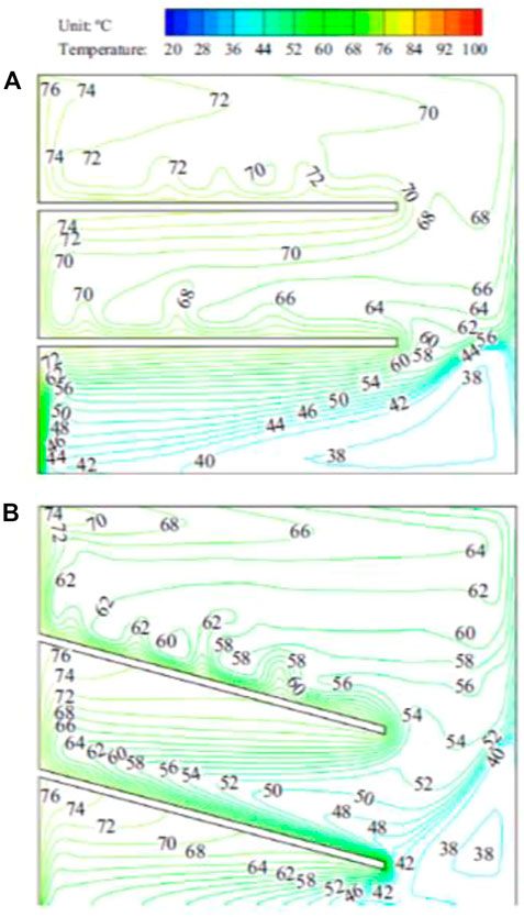
FIGURE 17. Temperature contours lines in the PCM domain at t = 10,000 s: (A) θ = 0° and (B) θ = 15°, with l/L = 0.75 and qn = 2500W/m2 (Ji et al., 2018).
6 Miscellaneous
Various innovative heat sink designs using fins are also discussed in the current literature. These designs include implementation of minichannels, microchannels and optimization of various fins geometries. Falahat et al, (2018) have studied heat transfer and laminar fluid flow characteristics of distilled water in the cylindrical heat sink with helical mini-channels. They have experimented by changing the helix angles and studying the effects on important thermal properties. Researchers observed a direct relation between helix angle and Reynolds and Nusselt numbers. 45° helix angle case has the highest Reynolds Number of 477 where the thermal performance factor reached 1.6. Hence, they advocate that the cylindrical heat sink with helical mini-channels is one of the best designs for effective cooling. A thermal performance factor is a criterion measured to measure the effectiveness of the heat transfer phenomenon. Thermal Performance Factor also abbreviated as TPF is, “The ratio of the relative effect of change in heat transfer rate to change in friction factor”. The generalised equation for the thermal performance factor is given as below,
Where Nu is Nusselt number given by,
Thermal performance factor is closely associated with the pressure drop phenomenon, higher the pressure drop is lower the thermal performance factor and vice versa.
P. Kumar et al. (Yadav et al., 2017) formulated a three-dimensional computational model to analyze the fluid flow and heat transfer in trapezoidal microchannel heat sink for the range of Reynolds number 96 to 720. Researchers observed that the trapezoidal-shaped channels have a 12% more heat transfer rate than the rectangular micro channels. The grooved microchannels showed a 28% enhancement in the heat transfer rate as a result of separation and redevelopment of the thermal boundary layer. This study presents the effectiveness of microchannels effectively.
Zhu et al, (2020) studied the three-dimensional CFD simulations of laminar flow and heat transfer in silicon-based microchannel heat sinks with rectangular grooves and different shaped ribs. They concluded that the performance and efficiency of microchannel heat sinks could be greatly enhanced if the internal passages were comprised of microchannels with grooves and ribs. They concluded that the overall performance obtained with rectangular ribs was the best at Reynolds numbers less than 500 at the flow inlet, but the elliptical ribs were more effective at Reynolds numbers greater than 500. Jing et al, (2020) coupled the FEM and RSM approaches were to explore the performance of non-Newtonian nanofluid flow in a cavity with heated fins of various shapes and in the presence of a vertical magnetic field in terms of both natural convection heat transfer and entropy formation. The effects of various parameters such as the Hartmann number and nanoparticles volume fraction and type on the heat transfer efficiency were also studied.
Hoi et al, (2019) studied the incompressible plate-fin heat sink forced convective heat transfer under the influence of fractal-induced turbulence and did numerical formulation and optimization. Researchers have combined the contributions of highly interactive, small and comparable turbulence length scale and high flow velocity adjacent to the plate-fin surface and have addressed the influence of fractal-induced turbulences on them. This novel research also studies the effects that fractal grids have on heat dissipation characteristics (Bhandari and Prajapati, 2020). proposed an open hit sink with varying fin heights. Water is considered as the cooling medium. The researchers infer that upon increasing the fin height, the higher heat transfer rate from the microchannel heat sink is sustained up to 1.5 mm; beyond this fin height, trend alters, and heat dissipation drops for the fin heights of 1.75 mm and 2.0 mm. Open microchannel heat sink with optimum fin height of 75%–80% exhibits better thermal performance compared to the equivalent heat sink of completely closed configuration. The coolant also helps in heat dissipation.
7 Heat sinks for modern applications
With electronic components getting smaller and smaller, heat sink design has become a challenging process (Soht et al., 2017). Researchers are coming up with innovative heat dissipation techniques using various PCMs, cooling fluid mixtures and innovative heat sink designs (Ngo et al., 2018), (Herrmann-Priesnitz et al., 2016). The following articles, which showcase the application of heat sinks for modern electronic components and architecture, are discussed below. Researchers also studied the integration of data from the Compact Thermal Model (CTM) and physical model for a multichip LED device with the multi-fin array (Chen et al., 2017). Two LED array models were studied, namely aligned array and staggered array. The staggered array clearly showed better thermal performance. They also proposed a method to model modern LED arrays.
Several studies were focussed on numerical simulation for electronics cooling and thermal management in which an alternative model were proposed for the better thermal efficiency by changing the thickness of the copper plate, replacing components and using new upper copper frame for enhanced heat dissipation (Boukhanouf and Haddad, 2010). This study is promising as it shows how the increased density of electronic components can be mounted on a PCB. In thermal management study, an F2/S2 hybrid heat sink were introduced with combined chip-level and hot-spot-level thermal management (Green et al., 2009). Large hot-spot fluxes approaching 400 W/cm2 can be dissipated efficiently using an F2/S2- designed system with minimal pumping power load with lower flux levels. Researchers concluded that the F2/S2 methodology offers a compact, power-efficient, and practical technique for the thermal management of modern electronic devices. In numerical simulation of heat disspation from LED of automotive headlights superior efficiency of the heat pipe with 4000 W/mK thermal conductivity were observed which help in maintaining the chip temperature within the safe operating range (Huang et al., 2018). A setup of grooved heat pipe with 2-mm-thick fins using a heat conductive PCB with the material of 180 W/mK thermal conductivity and a heat pipe with the material of 6000 W/mK thermal conductivity was highly effective and feasible. The effect of several parameters on the junction temperature of a high-power LED model was studied to confirm the thermal efficiency of the model developed (Kim et al., 2013). The impact of the thermal conductivity of the encapsulant and the matrix material on the bonding temperature was studied. The study also found the influence of the dielectric layer of the PCB on the junction temperature. For a small thermal conductivity, the impact of the thickness of the dielectric layer on the junction temperature predominates. Researchers developed an analytical model based on thermal resistance analysis to verify the CFD model of chimney-based LED bulb. The advantages of the chimney-based LED bulb over conventional LEDs are better utilization of the lampshade surface for heat dissipation. A gas mixture was introduced in the bulb, and the composition of this gas mixture was optimized using an analytical model. Researchers found that the mixture of 74% helium and 26% xenon caused in 30.7% lower temperature rise than that filled with air at the same power input (Feng et al., 2017).
8 Conclusion
This article presents an overview of the heat transfer enhancement techniques, analysis of different fin geometries, and the heat sink applications in modern electronic equipment. Researchers have performed extensive computational and experimental investigations on the selection and analysis of fin geometries and arrangements for various heat management applications. It is evident from the review that perforated fins have higher heat transfer rates compared to regular fins. The superiority of staggered fin arrangement when compared to the inline arrangement is also observed. Additionally, inclined fins are beneficial in terms of enhancing the heat transfer rates of the heat sink as well as distributing the heat energy uniformly. With the advent of micromachining, microchannel heat sinks are gaining attention and look promising but, further research in this field is necessary. New and innovative heat sink designs are also discussed in this article which is used in modern electronic applications like LED arrays, data centres and thermal management of computer chips.
In future study, more focus need to be given on the pressure drop, as it is one of the prime hurdle in development of micro-channel heat sink. Another scope of study is analyse the influence of surface roughness on heat transfer rather than the present scenario which are more focussed on fluid flow characteristics. There is till scope for development of cost effective manufacturing technology for the heat sink especially for the microfluidcs devices. Several machine learning algorithms such as ANN and its impact on the accuracy of the heat sink performance can be studied thoroughly.
Author contributions
AG contributed to the literature survey and conception of the study and wrote first draft of the study. AS and SS supervised the content of manuscript. All authors contributed to manuscript revision, read, and approved the submitted version.
Conflict of interest
The authors declare that the research was conducted in the absence of any commercial or financial relationships that could be construed as a potential conflict of interest.
Publisher’s note
All claims expressed in this article are solely those of the authors and do not necessarily represent those of their affiliated organizations, or those of the publisher, the editors and the reviewers. Any product that may be evaluated in this article, or claim that may be made by its manufacturer, is not guaranteed or endorsed by the publisher.
References
Ahmed, H. E., Salman, B. H., Kherbeet, A. S., and Ahmed, M. I. (2018). Optimization of thermal design of heat sinks: A review. Int. J. Heat. Mass Transf. 118, 129–153. doi:10.1016/j.ijheatmasstransfer.2017.10.099
Alam, T., and Kim, M. H. (2017). A comprehensive review on single phase heat transfer enhancement techniques in heat exchanger applications. Renew. Sustain. Energy Rev. 81, 813–839. doi:10.1016/j.rser.2017.08.060
Ansari, D., and Kim, K. Y. (2018). Hotspot thermal management using a microchannel-pinfin hybrid heat sink. Int. J. Therm. Sci. 134, 27–39. doi:10.1016/j.ijthermalsci.2018.07.043
Balan, A. S. S., Kullarwar, T., Vijayaraghavan, L., and Krishnamurthy, R. (2017). Computational fluid dynamics analysis of MQL spray parameters and its influence on superalloy grinding. Mach. Sci. Technol. 21 (4), 603–616. doi:10.1080/10910344.2017.1365889
Bash, A., Alkumait, A., and Yaseen, H. (2018). Experimental investigation of the influence of mechanical forced vibrations and heat flux on coefficientof heat transfer. Sci.J. Univ. Zakho 6 (3), 124–129. doi:10.25271/sjuoz.2018.6.3.519
Bhandari, P., and Prajapati, Y. K. (2020). Thermal performance of open microchannel heat sink with variable pin fin height. Int. J. Therm. Sci. 159, 106609. doi:10.1016/j.ijthermalsci.2020.106609
Boukhanouf, R., and Haddad, A. (2010). A CFD analysis of an electronics cooling enclosure for application in telecommunication systems. Appl. Therm. Eng. 30 (16), 2426–2434. doi:10.1016/j.applthermaleng.2010.06.012
Chen, H., Chen, F., Lin, S., and Xiong, C. (2017). Thermal analysis of a multichip light-emitting diode device with different chip arrays. IEEE Trans. Electron Devices 64 (12), 5001–5005. doi:10.1109/TED.2017.2766264
Ejlali, A., Ejlali, A., Hooman, K., and Gurgenci, H. (2009). Application of high porosity metal foams as air-cooled heat exchangers to high heat load removal systems. Int. Commun. Heat. Mass Transf. 36 (7), 674–679. doi:10.1016/j.icheatmasstransfer.2009.03.001
Falahat, A., Bahoosh, R., Noghrehabadi, A., and Rashidi, M. M. (2018). Experimental study of heat transfer enhancement in a novel cylindrical heat sink with helical minichannels. Appl. Therm. Eng. 154, 585–592. doi:10.1016/j.applthermaleng.2019.03.120
Farsad, E., Abbasi, S. P., Zabihi, M. S., and Sabbaghzadeh, J. (2011). Thermal analysis of 300W-QCW diode laser with copper foam heatsink. Symp. Photonics Optoelectron. SOPO 1, 1–4. doi:10.1109/SOPO.2011.5780604
Feng, S., Sun, S., Yan, H., Shi, M., and Lu, T. J. (2017). Optimum composition of gas mixture in a novel chimney-based LED bulb. Int. J. Heat. Mass Transf. 115, 32–42. doi:10.1016/j.ijheatmasstransfer.2017.07.006
González Gallero, F. J., Rodríguez Maestre, I., Hemida, H., and Álvarez Gómez, P. (2018). Practical approaches to assess thermal performance of a finned heat sink prototype for low concentration photovoltaics (LCPV) systems: Analytical correlations vs CFD modelling. Appl. Therm. Eng. 156, 220–229. doi:10.1016/j.applthermaleng.2019.04.086
Green, C., Fedorov, A. G., and Joshi, Y. K. (2009). Fluid-to-Fluid spot-to-spreader (f2/s2) hybrid heat sink for integrated chip-level and hot spot-level thermal management. J. Electron. Packag. Trans. ASME 131 (2), 0250021–02500210. doi:10.1115/1.3104029
Haghighi, S. S., Goshayeshi, H. R., and Safaei, M. R. (2018). Natural convection heat transfer enhancement in new designs of plate-fin based heat sinks. Int. J. Heat. Mass Transf. 125, 640–647. doi:10.1016/j.ijheatmasstransfer.2018.04.122
Herrmann-Priesnitz, B., Calderón-Muñoz, W. R., Valencia, A., and Soto, R. (2016). Thermal design exploration of a swirl flow microchannel heat sink for high heat flux applications based on numerical simulations. Appl. Therm. Eng. 109, 22–34. doi:10.1016/j.applthermaleng.2016.08.054
Hoi, S. M., Teh, A. L., Ooi, E. H., Chew, I. M. L., and Foo, J. J. (2019). Forced convective heat transfer optimization of plate-fin heat sink with insert-induced turbulence. Appl. Therm. Eng. 160, 114066. doi:10.1016/j.applthermaleng.2019.114066
Hu, X., Wan, H., and Patnaik, S. S. (2015). Numerical modeling of heat transfer in open-cell micro-foam with phase change material. Int. J. Heat. Mass Transf. 88, 617–626. doi:10.1016/j.ijheatmasstransfer.2015.04.044
Huang, C. H., Liu, Y. C., and Ay, H. (2015). The design of optimum perforation diameters for pin fin array for heat transfer enhancement. Int. J. Heat. Mass Transf. 84, 752–765. doi:10.1016/j.ijheatmasstransfer.2014.12.065
Huang, D. S., Chen, T. C., Te Tsai, L., and Lin, M. T. (2018). Design of fins with a grooved heat pipe for dissipation of heat from high-powered automotive LED headlights. Energy Convers. Manag. 180, 550–558. doi:10.1016/j.enconman.2018.11.021
Ishak, M. H. H., Ismail, F., Mat, S. C., Abdullah, M. Z., Abdul Aziz, M. S., and Idroas, M. Y. (2019). Numerical analysis of nozzle flow and spray characteristics from different nozzles using diesel and biofuel blends. Energies 12 (2), 281. doi:10.3390/en12020281
Jeong, J. H., Hah, S., Kim, D., Lee, J. H., and Kim, S. M. (2020). Thermal analysis of cylindrical heat sinks filled with phase change material for high-power transient cooling. Int. J. Heat. Mass Transf. 154, 119725. doi:10.1016/j.ijheatmasstransfer.2020.119725
Ji, C., Qin, Z., Low, Z., Dubey, S., Choo, F. H., and Duan, F. (2018).Non-uniform heat transfer suppression to enhance PCM melting by angled fins. Appl. Therm. Eng., 129. 269–279. doi:10.1016/j.applthermaleng.2017.10.030
Jing, D., Hu, S., Hatami, M., Xiao, Y., and Jia, J. (2020). Thermal analysis on a nanofluid-filled rectangular cavity with heated fins of different geometries under magnetic field effects. J. Therm. Anal. Calorim. 139 (6), 3577–3588. doi:10.1007/s10973-019-08758-9
Keshavarz, F., Mirabdolah Lavasani, A., and Bayat, H. (2019). Numerical analysis of effect of nanofluid and fin distribution density on thermal and hydraulic performance of a heat sink with drop-shaped micropin fins. J. Therm. Anal. Calorim. 135 (2), 1211–1228. doi:10.1007/s10973-018-7711-z
Khattak, Z., and Ali, H. M. (2019). Air cooled heat sink geometries subjected to forced flow: A critical review. Int. J. Heat. Mass Transf. 130, 141–161. doi:10.1016/j.ijheatmasstransfer.2018.08.048
Kim, I., Cho, S., Jung, D., Lee, C. R., Kim, D., and Baek, B. J. (2013). Thermal analysis of high power LEDs on the MCPCB. J. Mech. Sci. Technol. 27 (5), 1493–1499. doi:10.1007/s12206-013-0329-y
Mokhtari, M., Barzegar Gerdroodbary, M., Yeganeh, R., and Fallah, K. (2017). Numerical study of mixed convection heat transfer of various fin arrangements in a horizontal channel. Eng. Sci. Technol. Int. J. 20 (3), 1106–1114. doi:10.1016/j.jestch.2016.12.007
Ndlovu, P. L., and Moitsheki, R. J. (2019). Analysis of transient heat transfer in radial moving fins with temperature-dependent thermal properties. J. Therm. Anal. Calorim. 138 (4), 2913–2921. doi:10.1007/s10973-019-08306-5
Ngo, I. L., Jang, H., Byon, C., and Lee, B. J. (2018). Experimental study on thermal performance of SMD-LED chips under the effects of electric wire pattern and LED arrangement. Int. J. Heat. Mass Transf. 127, 746–757. doi:10.1016/j.ijheatmasstransfer.2018.08.089
Park, S. J., Jang, D., Yook, S. J., and Lee, K. S. (2015). Optimization of a staggered pin-fin for a radial heat sink under free convection. Int. J. Heat. Mass Transf. 87, 184–188. doi:10.1016/j.ijheatmasstransfer.2015.03.089
Park, S. J., and Lee, K. S. (2017). Orientation effect of a radial heat sink with a chimney for LED downlights. Int. J. Heat. Mass Transf. 110, 416–421. doi:10.1016/j.ijheatmasstransfer.2017.03.062
Qi, C., Sun, L., Wang, Y., Wang, C., and Chen, G. (2021). Thermo-hydraulic performance of nanofluids in a bionic fractal microchannel heat sink with traveling-wave fins. Korean J. Chem. Eng. 38 (8), 1592–1607. doi:10.1007/s11814-021-0836-y
Sahoo, L. K., Roul, M. K., and Swain, R. K. (2018). CFD analysis of natural convection heat transfer augmentation from square conductive horizontal and inclined pin fin arrays. Int. J. Ambient. Energy 39 (8), 840–851. doi:10.1080/01430750.2017.1354317
Sathe, T., and Dhoble, A. S. (2019). Thermal analysis of an inclined heat sink with finned PCM container for solar applications. Int. J. Heat. Mass Transf. 144, 118679. doi:10.1016/j.ijheatmasstransfer.2019.118679
Singh, P., and Patil, A. K. (2015). Experimental investigation of heat transfer enhancement through embossed fin heat sink under natural convection. Exp. Therm. Fluid Sci. 61, 24–33. doi:10.1016/j.expthermflusci.2014.10.011
Soht, M. Y., Teo, T. H., Ngt, W. X., and Yeo, K. S. (2017), Review of high efficiency integrated LED lighting. Proc. Int. Conf. Power Electron. Drive Syst. 12-15 December 2017. Honolulu, HI, USA. 93–97. doi:10.1109/PEDS.2017.8289181
Soodphakdee, D., Behnia, M., and Copeland, D. (2001). A comparison of fin geometries for heatsinks in laminar forced convection: Part I - round, elliptical, and plate fins in staggered and inline configurations. Int. J. microcircuits Electron. Packag. 24 (1), 68–76.
Tang, J., Qi, C., Ding, Z., Afrand, M., and Yan, Y. (2021). Thermo-hydraulic performance of nanofluids in a bionic heat sink. Int. Commun. Heat Mass Transf. 127, 105492. doi:10.1016/j.icheatmasstransfer.2021.105492
Tari, I., and Mehrtash, M. (2013). Natural convection heat transfer from inclined plate-fin heat sinks. Int. J. Heat. Mass Transf. 56 (1–2), 574–593. doi:10.1016/j.ijheatmasstransfer.2012.08.050
Yadav, R. K., Basak, R., and Pandey, K. M. (2017). Review on heat transfer from fins. IOP Conf. Ser. Mater. Sci. Eng. 225 (1), 012145. doi:10.1088/1757-899X/225/1/012145
Yu, X., Feng, J., Feng, Q., and Wang, Q. (2005). Development of a plate-pin fin heat sink and its performance comparisons with a plate fin heat sink. Appl. Therm. Eng. 25 (2–3), 173–182. doi:10.1016/j.applthermaleng.2004.06.016
Zhang, K., Li, M. J., Wang, F. L., and He, Y. L. (2020). Experimental and numerical investigation of natural convection heat transfer of W-type fin arrays. Int. J. Heat. Mass Transf. 152, 119315. doi:10.1016/j.ijheatmasstransfer.2020.119315
Keywords: heat sink design, perforated fins, inclined fins, heat sink applications, CFD analysis
Citation: Gaikwad A, Sathe A and Sanap S (2023) A design approach for thermal enhancement in heat sinks using different types of fins: A review. Front. Front. Therm. Eng. 2:980985. doi: 10.3389/fther.2022.980985
Received: 29 June 2022; Accepted: 13 September 2022;
Published: 12 January 2023.
Edited by:
Tapano Kumar Hotta, VIT University, IndiaReviewed by:
Cong Qi, China University of Mining and Technology, ChinaPrabhakar Bhandari, K.R. Mangalam University, India
Copyright © 2023 Gaikwad, Sathe and Sanap. This is an open-access article distributed under the terms of the Creative Commons Attribution License (CC BY). The use, distribution or reproduction in other forums is permitted, provided the original author(s) and the copyright owner(s) are credited and that the original publication in this journal is cited, in accordance with accepted academic practice. No use, distribution or reproduction is permitted which does not comply with these terms.
*Correspondence: Anilkumar Sathe, anilkumar.sathe@mituniversity.edu.in