 Yangli Ou1Yunfei Yan2Xiaolin Hou1Kuidong Yang1Wei Zhang1Chaoyang Zhong1Xiaohui Wang2
 Zhanyang Yu3Mingze Ma3*
- 1Longyuan New Energy Co., Ltd., Yantai, China
- 2Xi’an Thermal Power Research Institute Co., Ltd., Xi’an, China
- 3Shenyang University of Technology, Shenyang, China
As the core component of transformer, when the transformer is hit under short-circuit condition, the huge electromagnetic force will seriously aggravate the axial vibration of winding and even cause the damage of winding structure. In this paper, the electromagnetic load of transformer winding under short-circuit impact is solved, and based on the “spring-mass” model, the time-varying process of vibration displacement in the initial stage of short-circuit consists of 50 Hz and 100 Hz components. The axial dynamic process of inner winding is calculated by the simulation analysis method for transient structural field. It is found that the winding with the largest axial vibration displacement is not the winding with the largest axial electromagnetic force, and the axial vibration distribution of the winding is M-shaped. Based on the calculation model of one winding span, the axial vibration of the winding under non-uniform load is presented, which has an obvious stepped distribution at the interval of the spacers. And the vibration of the wingding between two spacers is larger than that at the end compression position. Finally, through the winding vibration test of the model transformer, the accuracy of the winding vibration model and the winding vibration distribution law are verified.
1 Introduction
As the core device of power transmission system, the operational reliability of power transformer directly affects the safety and stability of the power grid (Wu et al., 2023; Mitra et al., 2020; Tenbohlen et al., 2018). The mechanical deformation of windings is the main cause of transformer faults, among which the axial instability problem of windings caused by short-circuit conditions is particularly prominent. Therefore, the mechanical deformation under the short-circuit impact of windings is of great significance for improving the reliability of transformer and maintaining the safe and stable operation of power grid (Wang et al., 2016; Hong et al., 2021).
During the short-circuit process, axial electromagnetic excitation will cause significant vibration responses in the windings. This dynamic process may cause damage to the insulation structure and axial instability, thus leading to serious faults in the transformer (Zhang and Li, 2016).
In contrast, the radial electromagnetic force may cause the coil to bend or warp, but the amplitude of its dynamic displacement is relatively limited. Therefore, the study of the dynamic process of the axial vibration response of winding under the short-circuit condition of the transformer is a key theoretical basis for accurately evaluating the short-circuit resistance performance of the transformer, identifying potential fault modes and optimizing the mechanical structure (Shi et al., 2021; Kumar and Bakshi, 2022).
At present, the research on the axial vibration process of transformer windings under short-circuit conditions has been investigated, such as material mechanical property analysis, axial dynamic calculation methods, transient vibration characteristics, multi-physical field coupling algorithms and vibration monitoring technologies (Wu et al., 2024; Yan et al., 2024; Li et al., 2019). Most traditional short-circuit verification methods adopt static mechanical analysis. Although it can quickly obtain the magnetic field distribution and stress field characteristics, it fails to consider the time-varying influence of winding dynamic response and transient current on the leakage magnetic field. In recent years, researchers have proposed dynamic calculation methods to improve the accuracy of transformer short-circuit calculation (Jin et al., 2022). In Watts (1963), the axial mass-spring-damping equivalent model established provides a theoretical framework for the quantitative analysis of winding vibration. In Ji et al. (2020), the fault diagnosis method based on discrete frequencies and wideband vibration characteristics through the modal analysis method was summarized, but its research object did not cover the dynamic process of external short circuits. In Wang et al. (2019), Shan et al. (2021), the research was conducted respectively from the distribution characteristics of electromagnetic force and the transient displacement response, but did not fully consider the influence of material parameter differences. In Jin et al. (2023), the magnetic-structure bidirectional coupling algorithm proposed effectively reveals the influence mechanism of multi-physics field interaction on the vibration process.
Furthermore, the synergistic effect of electrical-thermal-mechanical stress during the long-term operation of the transformer will lead to the degradation of the mechanical properties of insulating materials, thereby changing the natural frequency characteristics of the windings (Zhang et al., 2020; Naranpanawe et al., 2019), and affecting their vibration response and the mechanical strength of the windings. In Zhang et al. (2022), the influence mechanism of the thermal accumulation effect of insulating materials on the short-circuit resistance capacity of windings by constructing a correlation model between thermal aging and mechanical property degradation is analyzed, and revealed deformation law and vibration response characteristics caused by multiple short-circuit impacts by using winding vibration detection technology. However, it lacked consideration of the cumulative factors of dynamic impact forces caused by multiple short-circuits.
In conclusion, the SFSZ9-40,000 kVA/110 kV transformer is taken as object and systematically conducts research on the axial dynamic process of the winding under short-circuit impact. Firstly, a three-dimensional electromagnetic-mechanical coupling model is established for electromagnetic load calculation, and the dynamic displacement characteristics of the winding are analyzed in combination with the analytical method. Secondly, a finite element model is constructed to simulate the axial dynamic process, and a cross-segment calculation model is established to reveal the vibration characteristics under non-uniform loads. Finally, the accuracy of the model and vibration distribution law were verified through vibration test. This research provides theoretical support for the improvement of the short-circuit resistance capacity and the structural optimization design of transformer.
2 Calculation of electromagnetic load under short-circuit impact
To analyze the dynamic process of the winding under short-circuit impact, a three-phase power transformer of model SFSZ9-40,000 kVA/110 kV is taken as a prototype for modeling and finite element. Table 1 shows the parameters of transformer.
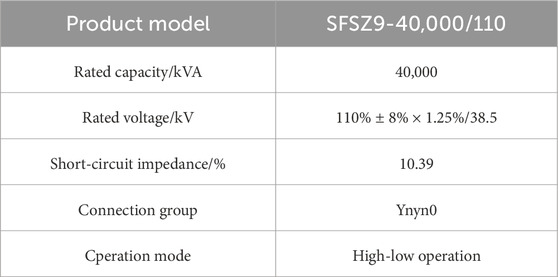
Table 1. Transformer parameters.
In this model, the high-voltage winding is the outer winding and the low-voltage winding is the inner winding. Both the high-voltage and low-voltage windings are composed of 68 coils. The outer winding and inner windings are precisely modeled. The three-dimensional model of transformer is shown in Figure 1. When conducting electromagnetic analysis, components such as spacers and braces that have little impact on the electromagnetic field can be ignored, and the eddy current effect of the wires can also be disregarded. Simulate the situation where the high-voltage and low-voltage windings of the transformer are subjected to short-circuit impact during operation, conduct coupling simulation calculations of the circuit and the magnetic field, and the electromagnetic field results under short-circuit impact is solved.
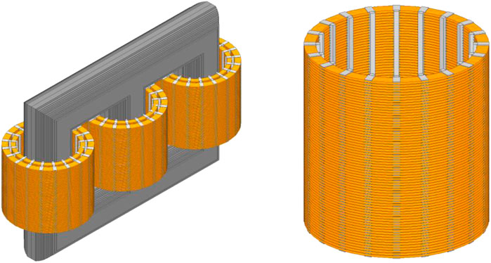
Figure 1. Three-dimensional finite element model of transformer.
The equation of the axial electromagnetic force is as follows (Jin et al., 2022).
where, γ is the attenuation time constant of the transient component.
It can be known from Equation 1 that the short-circuit electromagnetic force acting on the coil has three components. They are the attenuated aperiodic component, the periodic component of attenuation with a frequency of ω, and the steady-state components with a frequency of ω, respectively.
After the short-circuit current has attenuated completely and stabilized, the frequency of the electrodynamic force is twice that of the power grid. The electromagnetic force acting on the winding is proportional to the square of the excitation current. Therefore, the acceleration of the vibration signal obtained with the electromagnetic force as the load is also proportional to the square of the excitation current.
Because the short-circuit current flowing through the low-voltage winding is much greater than that through the high-voltage winding, the electromagnetic force of the low-voltage winding is much greater than that of the high-voltage winding. When the winding structure and materials are similar, the inner winding is more prone to deformation and damage. Therefore, in this section, the low-voltage winding is selected for electromagnetic force analysis.
Figure 2 shows the frequency domain diagram of the axial electromagnetic force of the top coil of the winding after Fourier decomposition during a short circuit of 0.02 s. In the initial stage of the short circuit, the amplitude of the fundamental frequency component (50 Hz) accounts for the main part. Figure 2 shows the frequency domain diagram of the axial electromagnetic force of the top coil of the winding after Fourier decomposition during the 1-s short circuit process. At this time, the amplitude of the second harmonic component (100 Hz) is the main part. If the electromagnetic force after short-circuit stabilization is simulated, it will be found that the amplitude of the 50 Hz component is nearly 0, indicating that the fundamental frequency of the winding load is 100 Hz. The analytical calculation and finite element results are consistent, demonstrating the accuracy of the simulation model.
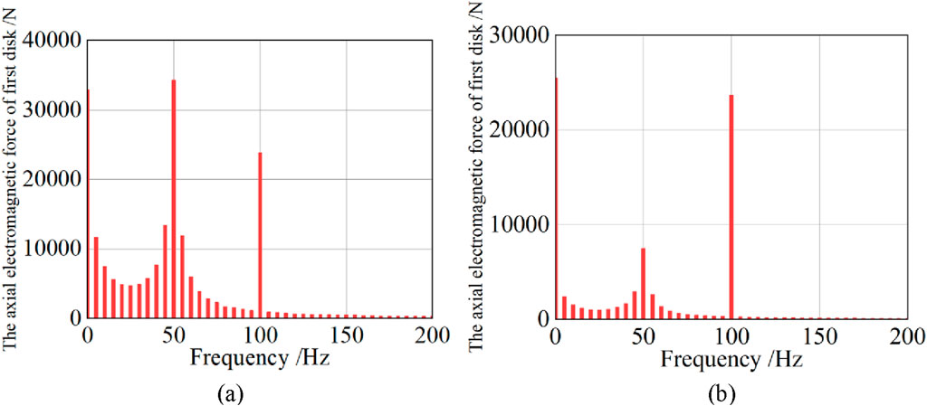
Figure 2. Fourier decomposition of axial electromagnetic force. (a) The frequency domain diagram of 0.02 s axial electromagnetic force. (b) Axial electromagnetic force frequency domain diagram.
It can be seen from Figure 3 that the force acting on the low-voltage winding is inward and the high-voltage winding is outward. The electromagnetic force acting on the low-voltage winding is much greater than that on the high-voltage winding, which is consistent with the theoretical analysis.
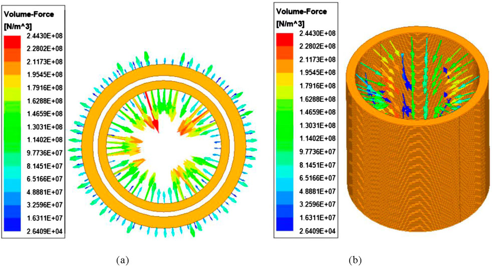
Figure 3. Winding electromagnetic force vector diagram in 0.01 s. (a) Vector diagrams of electromagnetic force for high-voltage and low-voltage windings. (b) Vector diagram of electromagnetic force of low-voltage winding.
As shown in Figure 4, it is the curve of the axial electromagnetic force acting on the low-voltage winding coil varying with time. At 0.01 s after the short circuit, the axial force of the first winding was the greatest, reaching 152 kN. The calculated value of its analytical equation was 155kN, with an error of 1.9%. Due to the symmetrical structure of the transformer winding, the magnitudes and variation laws of the axial forces of the topmost 1st coil and the bottom most 68th coil are basically the same. However, since the radial magnetic leakage at the position of the 35th winding in the middle is almost zero, the 35th winding is basically not subject to axial force.
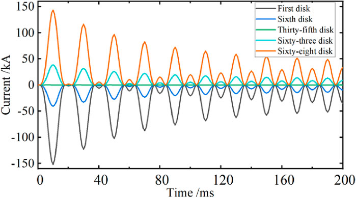
Figure 4. Axial electromagnetic force curves of low-voltage winding.
3 Axial vibration model of winding
Considering that the axial vibration amplitude of the winding in actual engineering is much larger than that in the radial direction, only the axial dynamic analysis and calculation are carried out. According to the structural characteristics of the transformer windings, each coil is regarded as a rigid body with the same mass. The insulating pad block is regarded as an elastic and damping element. Since the mass of the pad block is very small compared to that of the coil, a massless spring can be used as a substitute. Therefore, the axial dynamic process under the short-circuit impact of transformer winding can be simplified as the “spring-mass” model, as shown in Figure 5.
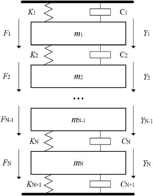
Figure 5. “Spring-mass” model.
Use YN to represent the axial displacement of the linear pie unit. CN is the coefficient of friction. KN the elastic coefficient of the pad block. mg is the mass of the line pie element, the equation of motion of the system can be obtained by Equation 2.
where, mNd2YN/dt2 represents the inertial force of the coil unit, CNdYN/dt represents the friction force of the coil unit in insulating oil, and KN is the elastic force of winding.
To simplify the equation, an approximate setting is made as Y1 = Y2 = … = YN = Y.
When the initial compression of the winding is kept consistent and unchanged, the elastic coefficient K is equal and is a constant. The magnitude of the C is related to the oil temperature of the transformer and is also set as a constant. Formula 3 can be derived based on Formula 1.
The natural oscillation frequency of winding is obtained by Equation 5.
The general solution of Equation 4 is obtained by Equation 6.
Through the above calculation, it is found that the vibration of winding under short-circuit impact consists of two parts. One is caused by the mechanical natural frequency of vibration system. The second type is caused by forced vibration under electromagnetic load. At the initial stage of a short-circuit, both the first harmonic and second harmonic components exist simultaneously. After the short-circuit current has completely attenuated, only the second harmonic vibration component remains. The amplitude of the vibration acceleration of winding is directly proportional to the square of the current. Due to the nonlinear characteristics of insulation spacer, the vibration signal will also contain high-order harmonic components. When the natural frequency approaches the first and second amplitudes of the excitation, the amplitudes of the two terms F and G will increase. To prevent resonance in the winding, the natural frequency of the winding should be kept away from the excitation frequency to reduce the damage of vibration to the winding.
4 Axial dynamic response calculation of winding
4.1 Calculation of the axial dynamic process of winding
The dynamic process of axial vibration of transformer is analyzed by using the transient structure. Calculate and analyze the vibration of the windings of a 40,000 kVA/110 kV power transformer. Taking the low-voltage winding as the research object, with the original height of the winding as the zero point, the upward vibration displacement of the winding is positive and the downward vibration displacement is negative. The transient calculation results are as follows.
As shown in Figure 6, the axial vibration displacement curves of the 1st and 68th winding are presented. It can be seen that the displacement of winding is continuously changing. The windings vibrate under the action of electromagnetic force. At the initial stage of short-circuit, due to the relatively large electromagnetic force, the winding vibrates more violently. Due to the damping effect of insulation spacer and the attenuation of the short-circuit aperiodic component, the amplitude of the winding attenuates rapidly and gradually transitions to the steady state. However, the time when the axial displacement of the coil reaches its peak lags slightly behind the time when the short-circuit current reaches its peak. The reason is that due to the elastic effect of the insulating pads between the wire discs, each wire disc of the transformer winding has inertia. When the wire disc is subjected to the maximum dynamic force, its vibration displacement continues to increase, and the vibration displacement reaches the maximum after a delay of 0.5 ms.
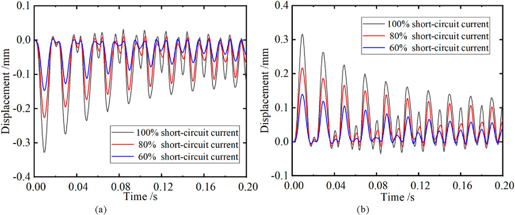
Figure 6. Axial vibration displacement curve of winding. (a) The average vibration displacement of the first winding. (b) The average vibration displacement of the 68th winding.
Under the condition of 100% short-circuit current, the maximum axial vibration displacement of the first winding is −0.330 mm, and the 68th winding is 0.318 mm. Under the action of axial force, the upper part of transformer winding is subjected to downward pressure, while the lower part is subjected to upward pressure. This results in an increase in the pressure on the middle part of the winding coil and a decrease in the pressure at the upper and lower ends of the winding. Due to the self-weight of the winding and the spacer block, the pressure of the upper part of the coil decreases and the pressure of the lower part increases, resulting in the axial vibration displacement of the first coil being slightly greater than that of the 68th coil. Meanwhile, through the dynamic response calculation of 60%, 80% and 100% electromagnetic loads, it was found that with the decrease of short-circuit current, the vibration of the upper and lower end line discs was significantly weakened.
Figure 7 shows the axial vibration displacement distribution of the 1st and 68th winding at the time of 0.01 s, where the transparent winding represents the initial position of this winding. It can be observed that the direction of the maximum amplitude of the top end of winding is downward vibration, and the direction of the maximum amplitude of the bottom end of winding is upward vibration. Under the compression of the two end pads, the winding shows an arched vibration trend among each pad.
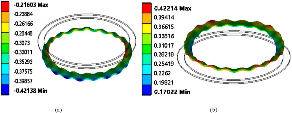
Figure 7. Axial vibration displacement nephogram of winding in 0.01. (a) The vibration displacement cloud map of the first winding. (b) The 68th piece is the vibration displacement cloud map.
Figure 8 Clearly shows that due to the action of the axial short-circuit force, the upper and lower end line discs are squeezed towards the middle. Although the resultant force on the middle line disc is the smallest, its pressure is greater than that of the two end line discs. The equivalent stress of the middle line disc at 0.01 s is 57.4 MPa.
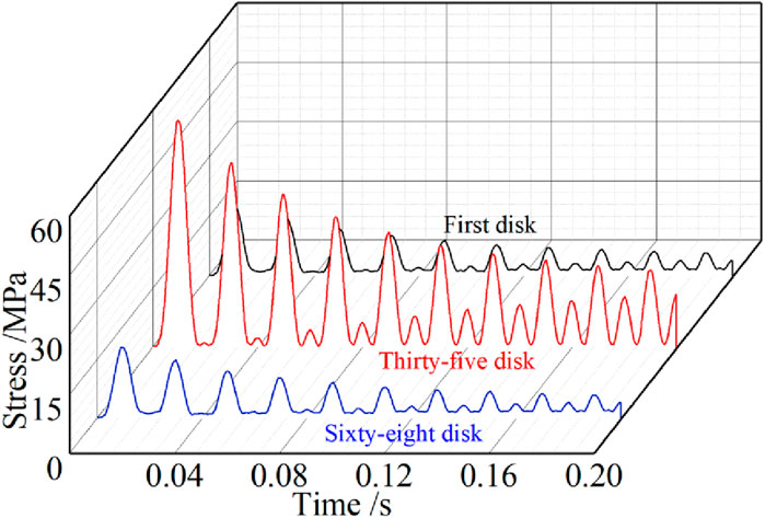
Figure 8. Stress curves with time of each winding.
4.2 Calculation of axial vibration distribution of windings
In order to obtain the distribution law of axial vibration, the average vibration displacement of the coil vibration under uniform load was taken. Through calculation, it was found that the position with the most intense axial vibration of the winding was not located at the end with the greatest axial force. As shown in Table 2, at the same time, the axial vibration displacements at the 10th and 60th coils are much greater than those at the upper and lower end coils. However, the maximum attenuation rates occur at the upper and lower end coils of the winding, which are 64.2% and 65.4%, respectively.
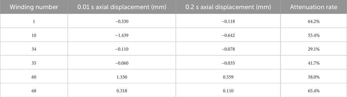
Table 2. Axial vibration displacement of winding.
From Figure 10a, it can be observed that the maximum axial vibration displacements of the upper and lower parts of winding are respectively distributed at approximately 1/6 and 5/6 of the winding. In order to further analyze the axial vibration distribution law of the winding, it is now regarded as a uniform load to solve the average axial vibration displacement of each coil. The average axial vibration displacement of each winding at 0.01 s was processed and made as b in Figure 9. The research finds that the coil with the largest displacement does not occur at the end of the winding subjected to the greatest axial electrodynamic force, but at the 10th and 60th coils, which are −1.439 mm and 1.330 mm respectively.
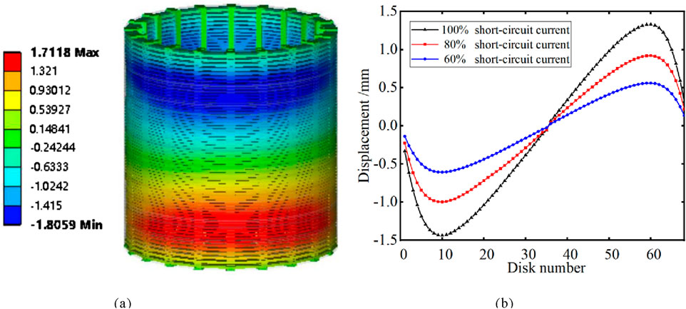
Figure 9. Axial vibration displacement of winding with the time of 0.01 s. (a) Cloud diagram of winding vibration displacement. (b) Winding vibration displacement distribution curve.
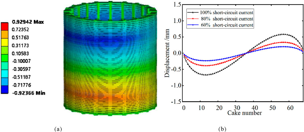
Figure 10. Axial vibration displacement of winding with the time of 0.01 s. (a) Cloud diagram of winding vibration displacement. (b) Winding vibration displacement distribution curve.
The axial vibration displacement of the winding is distributed in an “M” -shaped pattern. Therefore, there is no absolute correspondence between the vibration displacement and the electrodynamic force law. The upper and lower end line discs are compressed by the end rings, which offsets part of the vibration energy of the system, resulting in the extreme points of axial vibration displacement not appearing at the upper and lower ends. Through the calculation of the axial vibration distribution under different short-circuit currents, it is found that the magnitude of the short-circuit current does not affect the vibration displacement distribution law, but only changes the magnitude of the vibration displacement.
Compared Figure 10 with Figure 9, it can be found that the vibration displacements of each part have decreased significantly with the attenuation of short-circuit current and short-circuit force. At 0.2 s, the displacement of the 14th winding is −0.67 mm, and the displacement of the 57th winding is 0.58 mm. The overall distribution law of its axial vibration displacement is approximately the same as that of 0.01 s, still showing an “M” -shaped regular distribution, but the position where its maximum vibration displacement occurs has changed.
As shown in Table 3, when the winding displacement distribution is 0.01 s, the vibration displacement of winding at the upper and lower symmetrical parts is asymmetric, and the degree of asymmetry is approximately 8.2%. When the short circuit reaches 0.2 s, its asymmetry increases to 14.3%. This asymmetric difference in displacement stems from the cumulative effect of forces, and this difference will intensify as the short circuit develops.
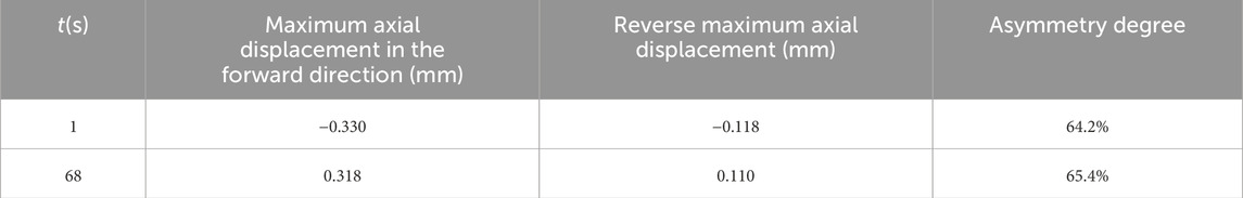
Table 3. Axial vibration displacement of winding.
5 Calculation of the circumferential distribution of the vibration of the line pie
At present, the load of windings is usually simplified as a uniformly distributed load model for analysis. However, since the magnetic field inside and outside core window are not exactly the same, the electromagnetic force is not uniformly distributed along the circumferential direction, which in turn causes differences in the vibration of the wire sheet along the circumferential direction.
Previously, the existing vibration models only compared the vibration responses inside and outside the window, but did not analyze the circumferential vibration distribution of winding. Only reference (Tenbohlen et al., 2018) mentioned that the suspended part of the coil has no contact with the pad block, so it may have different vibration responses in the axial and amplitude directions from insulation spacer and winding. However, the research on the circumferential distribution of the winding vibration under uneven load excitation has not been involved. Therefore, in order to analyze the circumferential distribution of axial vibration, one-quarter of the winding was axially divided into five spans for axial dynamic simulation, as shown in Figure 11. The circumferential non-uniform load of the cross-span model is shown in Figure 12.
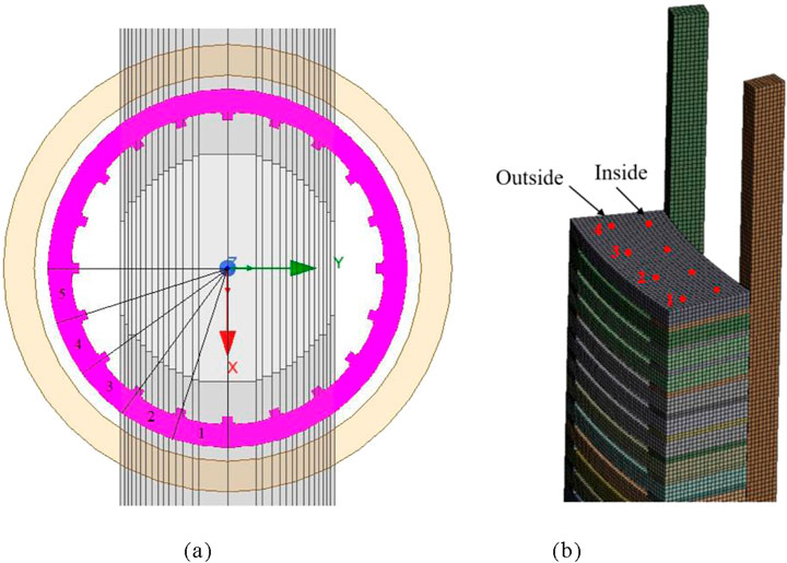
Figure 11. One span simulation model. (a) Cross-sectional model. (b) Finite element measured point distribution.
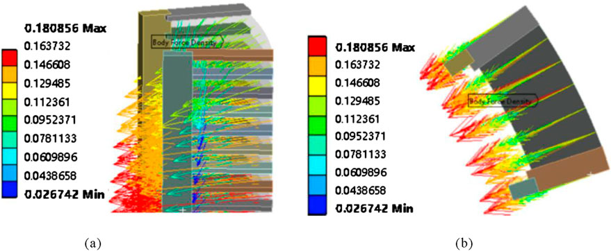
Figure 12. Circumferential non-uniform load. (a) Main view. (b) Top view.
A quarter-circular circumferential vibration distribution was made at 20 measured points across 5 spans, as shown in Figure 13. Under circumferential non-uniform loading, the vibration of the winding shows a distinct stepwise distribution along the circumferential direction with the spacers as intervals. The amplitudes of the winding segments between every two spacers are basically the same, and the vibration displacements of the winding segments at both ends of a spacer will increase or decrease in a jumping manner. It is precisely due to the compression of all the spacers along the axial direction that the vibration of the winding sections between the spacers is not synchronous. The vibration of the spacers and the adjacent winding sections can no longer be analyzed as a uniform load. As a result, under the circumstances of the non-uniform circumferential distribution of the leakage magnetic field and electromagnetic force, the vibration of each winding section is distributed in a stepwise manner. Through careful observation, it can also be found that the amplitude distribution of the winding segment between the two spacers also follows a certain pattern. Due to the compression of the spacers, the vibration displacement in the middle of the line pie section is slightly greater than that at both ends of the radial line pie section. If the grid is divided more finely, this conclusion should be more obvious. Moreover, the magnetic flux density is the greatest at the main open circuit, and the outer side of the inner winding is closer to the main open circuit. Therefore, the vibration on the outer side is more intense than that on the inner side. The following will explore the reason for the most intense vibration in the fourth span from an electromagnetic perspective.
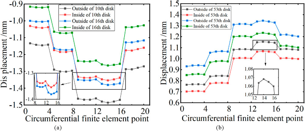
Figure 13. Circumferential distribution of winding vibration. (a) The vibration circumferential distribution of the 10th and 16th winding. (b) The vibration circumferential distribution of the 53rd and 60th winding.
The circumferential distribution of radial magnetic flux density of winding was obtained by solving the electromagnetic field under the short-circuit impact of the coil, as shown in Figure 14. The radial magnetic flux density of each coil reaches the peak at the 4th span, and the distribution law of the radial leakage magnetic field of each coil is similar to the circumferential distribution law of vibration. It is precisely because the radial magnetic flux density reaches its maximum at the 4th span that the axial electromagnetic force load is the greatest at this point, thereby causing the winding vibration to be the most intense at this location.
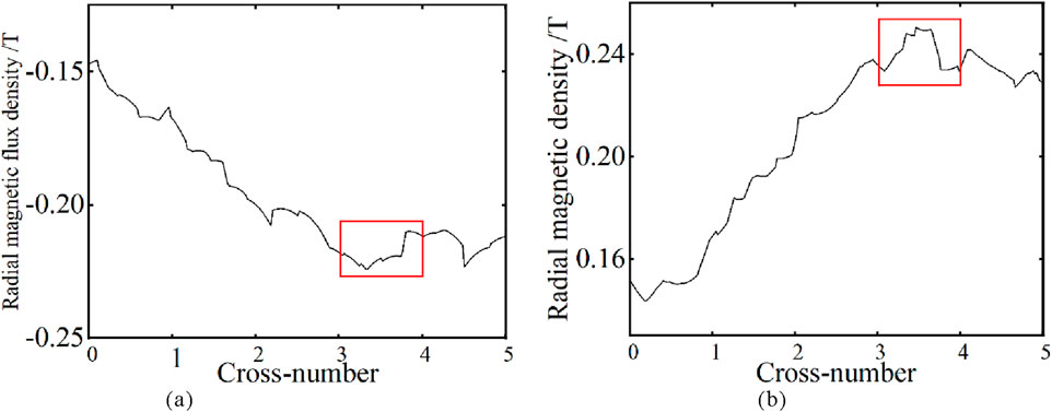
Figure 14. Circumferential distribution of winding radial leakage flux density. (a) The 10th winding radial magnetic flux density. (b) The 60th winding radial magnetic flux density.
Therefore, when conducting winding vibration analysis, the leakage magnetic field can be calculated firstly. The circumferential distribution of the axial vibration of winding can be approximately estimated by combining the calculation of the radial magnetic field with the viewpoint of the stepwise distribution of vibration.
6 Vibration test for transformer winding
Since the 40,000 kVA/110 kV power transformer used in this paper cannot undergo vibration tests due to the reasons of the test conditions, in this section, under the condition of ensuring the operability of the test, a 800 kVA/6 kV transformer prototype is taken as an example for vibration test. This transformer is a three-phase transformer specially customized by the research group for experimental research. Its windings are wrapped with insulating paper and exposed. Vibration signals can be directly obtained by arranging vibration sensors on the surface of windings, ensuring that the obtained vibration signals have less interference. The flowchart of the vibration test is shown in Figure 15. The sensor probe is adhered to the winding with wax, which will not interfere with the leakage magnetic distribution of the transformer and can obtain a good vibration signal.
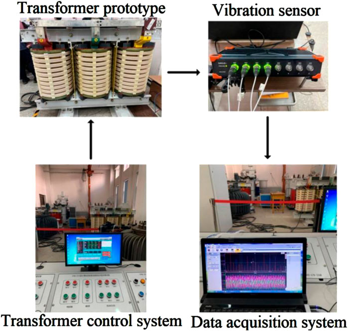
Figure 15. Schematic diagram of transformer vibration test.
Since the distribution of the circumferential spacers is different from that of the 40,000 KVA transformer in the previous section, the sensor is arranged near the window where the axial electromagnetic force is relatively large. Three measured points are respectively arranged. Measured points 1 and 3 are located at nearly 1/6 and 5/6 of the axial direction with the maximum vibration displacement, and measured point 2 is located in the middle of the winding, as shown in Figure 16.
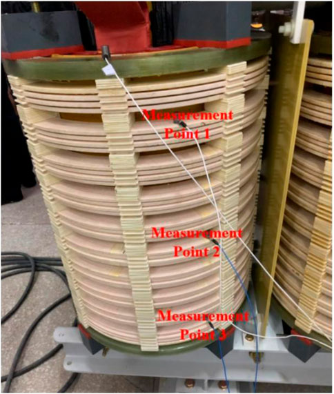
Figure 16. Placement positions of three vibration acceleration sensors.
As shown in Figure 17, the amplitude of fundamental frequency vibration acceleration at each measuring point of the winding exhibits a significant increasing trend with the rise of current percentage, and shows an approximate linear relationship with the square of current percentage. This result not only verifies the accuracy of the winding vibration model, but also fully demonstrates the scientific correctness of the test scheme.
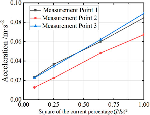
Figure 17. Relationship between different load current and vibration acceleration.
As shown in Figure 18, it is the spectral diagram of the axial vibration of measured points 1 to 3 at the rated current. It can be found that the amplitude of winding vibration acceleration at points 1 and 3 is much greater than that at measured point 2. According to the setting of the measured points, the results are in line with the analysis of the axial vibration distribution in Section 4. The vibration signals at points 1 to 3 contain vibration signal components exceeding 100 Hz, and their amplitudes show a decreasing trend as the frequency increases. This might be due to the very small excitation voltage, but the vibration of the core is still transmitted to the winding. The vibration of the structural components and the core jointly cause the vibration signal of the winding to contain a small amount of high-order harmonics.
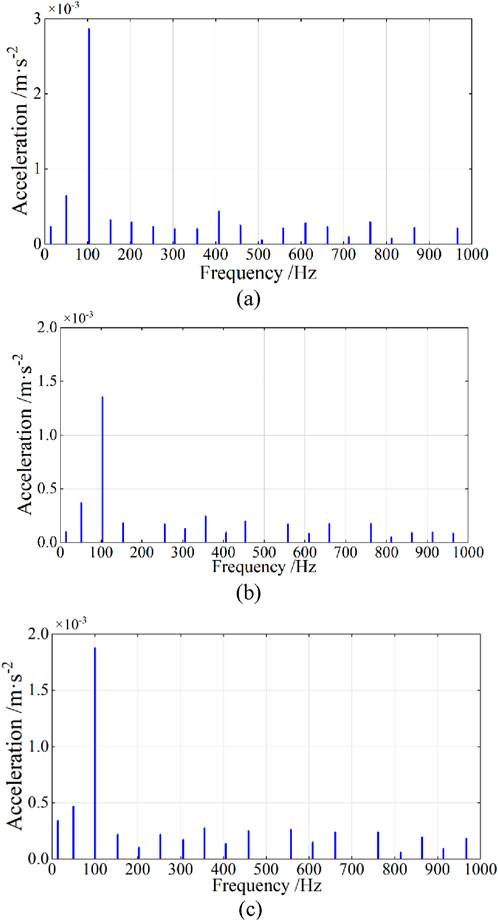
Figure 18. Frequency response of winding vibration at the state of load test. (a) Measured Point 1. (b) Measured Point 2. (c) Measured Point 3.
7 Conclusion
In this paper, a finite element simulation model was established based on actual transformer, and the electromagnetic load of the winding, the axial dynamic process and the circumferential distribution of vibration were simulated and calculated using this model. Combined with the test results, the following conclusions were obtained.
(1) Under short-circuit impact, the electromagnetic load of the winding and the time-varying process of the axial vibration of the winding both contain 50 Hz and 100 Hz components before the short-circuit reaches a steady state.
(2) The winding with the greatest axial vibration displacement is not the upper and lower end winding with the greatest axial electromagnetic force. The axial vibration distribution of the winding follows an “M” shaped pattern.
(3) With the passage of short-circuit time and the accumulation of winding vibration, the asymmetry of the upper and lower vibration of the winding increases, and the attenuation rate of the upper and lower ends of the winding is the greatest.
(4) Under uneven load, the axial vibration of the winding shows a distinct stepped distribution along the circumferential direction with the spacers as intervals, and the vibration of the suspended winding section between the two spacers in the radial direction is greater than that at the end compression area.
Data availability statement
The original contributions presented in the study are included in the article/supplementary material, further inquiries can be directed to the corresponding author.
Author contributions
YO: Data curation, Conceptualization, Writing – original draft. YY: Supervision, Software, Writing – original draft. XH: Investigation, Writing – review and editing, Methodology. KY: Writing – original draft, Conceptualization. WZ: Investigation, Writing – original draft, Methodology. CZ: Methodology, Formal Analysis, Writing – original draft. XW: Writing – original draft, Conceptualization, Investigation. ZY: Software, Writing – original draft, Writing – review and editing. MM: Writing – original draft, Writing – review and editing, Conceptualization.
Funding
The author(s) declare that no financial support was received for the research and/or publication of this article.
Conflict of interest
Authors YO, XH, KY, WZ, and CZ were employed by Longyuan New Energy Co., Ltd. Authors YY and XW were employed by Xi’an Thermal Power Research Institute Co., Ltd.
The remaining authors declare that the research was conducted in the absence of any commercial or financial relationships that could be construed as a potential conflict of interest.
Generative AI statement
The author(s) declare that no Generative AI was used in the creation of this manuscript.
Publisher’s note
All claims expressed in this article are solely those of the authors and do not necessarily represent those of their affiliated organizations, or those of the publisher, the editors and the reviewers. Any product that may be evaluated in this article, or claim that may be made by its manufacturer, is not guaranteed or endorsed by the publisher.
References
Hong, K., Jin, M., and Huang, H. (2021). Transformer winding fault diagnosis using vibration image and deep learning. IEEE Trans. Power Del. 36 (2), 676–685. doi:10.1109/tpwrd.2020.2988820
Ji, S., Zhang, F., and Shi, Y. (2020). Review on vibration-based mechanical condition monitoring in power transformers. High. Volt. Eng. 46 (1), 257–272.
Jin, M., Chen, W., Zhao, Y., Wen, T., Wu, J., Wu, X., et al. (2022). Coupled magnetic-structural modeling of power transformer for axial vibration analysis under short-circuit condition. IEEE Trans. Magn. 58 (7), 1–9. doi:10.1109/tmag.2022.3175245
Jin, M., Guo, P., Chen, W., Gao, F., Zhang, Q., and Wen, T. (2023). Two-way magnetic-structural coupling effect on vibration process of power transformer windings. High. Volt. Eng. 49 (8), 3296–3304. doi:10.13336/j.1003-6520.hve.20221550
Kumar, I., and Bakshi, A. (2022). Effects of axial sticks and proof stress of conductor material on the buckling strength of transformer inner winding. IEEE Trans. Power Del. 37 (6), 5465–5468. doi:10.1109/tpwrd.2022.3189539
Li, L., Liu, X., Zhu, G., Chen, H., and Gao, S. (2019). Research of short-circuit performance of a split-winding transformer with stabilizing windings. IEEE Trans. Appl. Supercond. 29 (2), 1–6. doi:10.1109/tasc.2018.2889271
Mitra, A., Xu, X., and Benidris, M. (2020). Reduction of three-phase transformer inrush currents using controlled switching. IEEE Trans. Ind. Appl. 56 (1), 890–897. doi:10.1109/tia.2019.2955627
Naranpanawe, L., Ekanayake, C., and Saha, T. K. (2019). Measurements on pressboard to understand the effect of solid insulation condition on monitoring of power transformer winding clamping pressure. IET Sci. Meas. Technol. 13 (2), 186–192. doi:10.1049/iet-smt.2018.5096
Shan, Y., Ai, M., and Liu, W. (2021). Research on simulation calculation on short-circuit electrodynamics force of power transformer winding. Int. J. Appl. Electromagn. Mech. 65 (3), 451–465. doi:10.3233/jae-200021
Shi, Y., Ji, S., Zhang, F., Dang, Y., and Zhu, L. (2021). Application of operating deflection shapes to the vibration-based mechanical condition monitoring of power transformer windings. IEEE Trans. Power Del. 36 (4), 2164–2173. doi:10.1109/tpwrd.2020.3021909
Tenbohlen, S., Schmidt, N., Breuer, C., Khandan, S., and Lebreton, R. (2018). Investigation of thermal behavior of an oil-directed cooled transformer winding. IEEE Trans. Power Del. 33 (3), 1091–1098. doi:10.1109/tpwrd.2017.2711786
Wang, S., Wang, S., Zhang, N., Yuan, D., and Qiu, H. (2019). Calculation and analysis of mechanical characteristics of transformer windings under short-circuit condition. IEEE Trans. Magn. 55 (7), 1–4. doi:10.1109/tmag.2019.2898183
Wang, S., Zhang, H., Li, H., and Yuan, D. (2016). Cumulative deformation analysis for transformer winding under short-circuit fault using magnetic-structural coupling model. IEEE Trans. Appl. Supercond. 26 (7), 0–5. doi:10.1109/tasc.2016.2584984
Watts, G. B. (1963). A mathematical treatment of the dynamic behaviour of a power-transformer winding under axial short-circuit forces. Proc. Inst. Electr. Eng. 110 (3), 551–560. doi:10.1049/piee.1963.0080
Wu, S., Ji, S., Zhang, Y., Wang, S., and Liu, H. (2024). A novel vibration frequency response analysis method for mechanical condition detection of converter transformer windings. IEEE Trans. Ind. Electron. 71 (7), 8176–8180. doi:10.1109/tie.2023.3301514
Wu, S., Zhang, F., Dang, Y., Zhan, C., Wang, S., and Ji, S. (2023). A mechanical-electromagnetic coupling model of transformer windings and its application in the vibration-based condition monitoring. IEEE Trans. Power Del. 38 (4), 2387–2397. doi:10.1109/tpwrd.2023.3242266
Yan, C., Xu, C., Liu, H., Kang, S., and Zhang, B. (2024). Numerical and experimental investigations on transformer winding damages under multiple short-circuit faults. IEEE Trans. Appl. Supercond. 34 (8), 1–5. doi:10.1109/tasc.2024.3463515
Zhang, B., and Li, Y. (2016). Research on radial stability of large transformers windings under multiple short-circuit conditions. IEEE Trans. Appl. Supercond. 26 (7), 1–4. doi:10.1109/tasc.2016.2594843
Zhang, F., Ji, S., Ma, H., and Saha, T. K. (2020). Operational modal analysis of transformer windings. IEEE Trans. Power Del. 35 (3), 1285–1298. doi:10.1109/tpwrd.2019.2939388
Keywords: amorphous alloy, clamping force, magnetization characteristic, magnetostriction, electromagnetic vibration
Citation: Ou Y, Yan Y, Hou X, Yang K, Zhang W, Zhong C, Wang X, Yu Z and Ma M (2025) Research on axial dynamic process of power transformer windings under short-circuit shock. Front. Energy Res. 13:1623160. doi: 10.3389/fenrg.2025.1623160
Received: 06 May 2025; Accepted: 04 July 2025;
Published: 17 July 2025.
Edited by:
Jasronita Jasni, Putra Malaysia University, MalaysiaCopyright © 2025 Ou, Yan, Hou, Yang, Zhang, Zhong, Wang, Yu and Ma. This is an open-access article distributed under the terms of the Creative Commons Attribution License (CC BY). The use, distribution or reproduction in other forums is permitted, provided the original author(s) and the copyright owner(s) are credited and that the original publication in this journal is cited, in accordance with accepted academic practice. No use, distribution or reproduction is permitted which does not comply with these terms.
*Correspondence: Mingze Ma, c3V0bW16QDE2My5jb20=