 Liangliang Dong1*†
 Bo Li
Bo Li Xiaohua Zhu
- 1School of Mechatronic Engineering, Southwest Petroleum University, Chengdu, China
- 2CNPC Bohai Petroleum Equipment Manufacturing Co., Ltd, Tianjin, China
For horizontal wells with small wellbores and large-diameter pipe strings, pipe sticking is prone to occur during oilfield completion operations. Avoiding pipe sticking can effectively save construction costs. In this paper, dynamics and Hertz contact theory are adopted, taking into account the influence of small wellbores and large-diameter pipe strings. Based on the principle of scaling, an experimental bench for the running-in of completion pipe strings is built, and a three-dimensional finite element model for analyzing the axial force and contact force of the completion pipe strings in the open-hole staged fracturing is established. The variation laws of the wellhead axial force, axial force along the well depth and contact force during the running-in process of the completion pipe strings are analyzed. The results show that with the increase in the packer size and friction coefficient in the open-hole section and the decrease in the radius of the open-hole section, the wellhead axial force will decrease, and the contact force will increase accordingly. The neutral point moves upward, the length of the pipe string section under axial pressure increases, and the pipe strings with buckling deformation are all under axial pressure. The pipe string will first buckle near the kick-off point, and then the buckling will extend upward along the straight section from the kick-off point. Moreover, the closer to the kick-off point, the more severe the buckling. The research in this paper provides a theoretical basis for the decision-making of the running-in of completion pipe strings.
1 Introduction
The running-in of horizontal wells can lead to many mechanical problems, including axial force applied at the wellhead, contact force and frictional force generated by the contact between the pipe string and the wellbore wall. The pipe string may experience buckling as shown in Figure 1 (such as sinusoidal buckling, helical buckling, mixed buckling), wear, plastic deformation and failure. This will reduce the service life of the pipe string, delay the construction progress and cause serious economic losses (Li et al., 2023; Alzahabi et al., 2024). The axial force and contact force on the pipe string are the main factors affecting the failure of the pipe string. Therefore, through the study of the mechanics of horizontal well pipe strings, analyzing the influencing factors and variation laws of the axial force and contact force on the completion pipe string during the running-in process is of great significance for improving the production efficiency of oil and gas wells, prolonging the lifespan of the pipe string, avoiding abnormal damage to the pipe string and ensuring safe production.
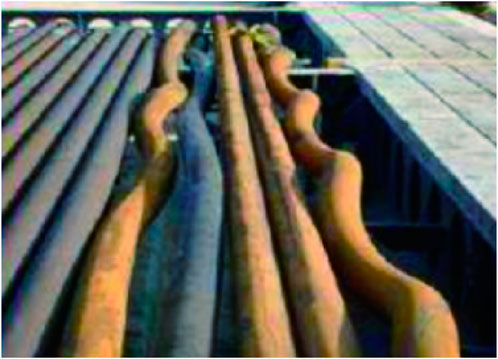
Figure 1. Schematic diagram of coiled tubing buckling (Dong, 2018).
Many scholars have conducted theoretical and field studies on well completion in the oil and gas industry. Shokry et al. (2024) successfully eliminated intermediate casing string from the design thereby achieving not only a 33% reduction in dry hole cost/meter, but also delivering wells and producing oil 25% faster than before. Removing an intermediate casing string resulted in a longer open hole. And describes how two string design was successfully engineered and executed serves as a guide for selecting proper candidates for this design and an operational guide for two section wells design. Galasso et al. (2025) propose a method for the simulation of the nonlinear dynamics of drill-string systems and the assessment of the stresses to which the pipe is subject under realistic conditions in drilling operations (Shan et al., 2024). Shan et al. (2024) based on the force analysis and calculation of pipe string, combined with the field practice, and taking into account technical challenges such as extreme depth and ultra-long open-hole sections, have formed the integration of oil test and completion, which is centered around “clean well completion, open-hole long support, shallow completion string and soft stratification transformation”, realizing the operational objectives of integration of testing, acid fracturing, completion and oil production. Al-Khaldi et al. (2021) by modeling the geomechanical properties of each formation, determined the range of mud density and rheological properties capable of stabilizing all eight formations. They successfully stabilized high-pressure formations and ultimately achieved the target total depth with a single borehole.
However, the above-mentioned research mainly focuses on static calculations. But under the condition of a small wellbore and a large pipe string size, the pipe string encounters great resistance when it is lowered into the open hole section, and the movement between the pipe string and the wellbore wall of the open hole section is complex, so dynamic analysis should be carried out. In order to smoothly lower the completion string to the designated position, this study, by means of a combination of numerical simulation and experimental measured data analysis, explores the influencing factors and variation laws of the axial force during the running-in of open-hole staged fracturing completion string under the condition of a small wellbore and a large pipe string size. It analyzes under which working conditions the pipe string is most prone to buckling deformation, identifies the well section where the pipe string is prone to deformation, and then strengthens the strength of the pipe string in this section. This has important guiding significance for the mechanical analysis and string combination of the running-in of small wellbore and large diameter open-hole staged fracturing completion string.
2 Numerical model
2.1 Kinematic equations
The tools for open-hole staged fracturing completion strings mainly consist of tubing, open-hole packers, and ball-dropping sleeves. Figure 2 is a schematic diagram of the structure of a multi-stage fracturing completion string.
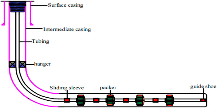
Figure 2. Schematic diagram of the structure of a multi-stage fracturing completion string.
During the lowering process of the staged fracturing completion string, the string mainly bears axial forces. Axial force refers to the tensile or compressive force acting along the axial direction of the tubing. Generally, the tubing at the wellhead is under tensile force, while at the bottom of the tubing, due to the buoyancy of the fluid, the tubing will be under compressive force. In the presence of packers, the tubing at the packer location may also be subject to compressive force (Amir and Ahmed, 2021; Amir et al, 2021). The effective axial force on the tubing string is mainly the combined axial force resulting from the tensile force due to the tubing’s own weight, buoyancy, friction force, drag force, bending moment, additional axial force due to changes in temperature and pressure within the well after completion, and compressive force induced by packers (Zhu et al., 2008; Zhu et al., 2019).
Figure 2 shows the vertical profile of the wellbore trajectory for a horizontal well.
In actual horizontal wells, the vertical tensile force generated by the tubing in the horizontal section is zero, and the vertical tensile force generated in the build-up section is also less than the total weight of the tubing in that section. Derive the following formulas in detail based on the mechanics of horizontal well pipe strings (Lian et al., 2002; Lian et al., 2006; Lian et al., 2015). As shown in Figure 3, take an infinitesimal segment
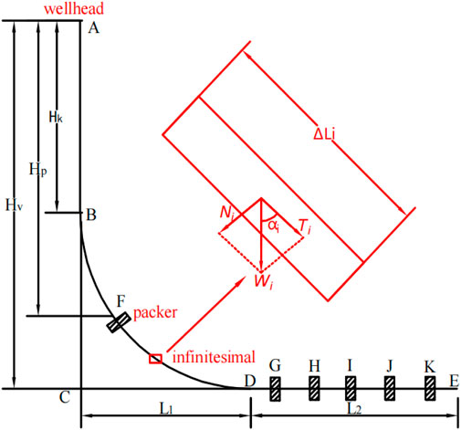
Figure 3. Vertical profile diagram of the wellbore trajectory for a horizontal well.
In the formula:
2.1.1 The additional force caused by the friction between the tubing string and the wellbore wall
When the tubing in a horizontal well moves within the wellbore, it will generate dynamic additional tensile force. When there is no fluid in the tubing, the dynamic additional tensile force is composed of the friction force generated by the normal force between the tubing and the wellbore wall in both the build-up section and the horizontal section. The friction coefficient is denoted as
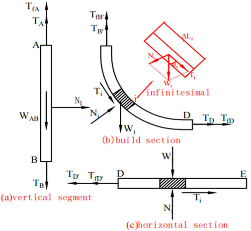
Figure 4. Mechanical model diagram of the completion tubing string for a horizontal well.
Due to the relatively small size of the wellbore and the larger size of the tubing string, the tubing string will come into contact with the wellbore wall in the vertical section, generating a compressive force
Equation 5 represents the additional dynamic tensile force when the tubing is being lifted or lowered. When the tubing is being lifted,
In the above equations:
2.1.2 Mathematical model for the mechanics of horizontal well tubing strings with packers
When the packer is located in the build-up section and the horizontal section, as shown in Figure 1, the packer (F) is at the kick-off point, and
In the equation:
Similarly, when multiple packers are used for staged fracturing in the horizontal section, the actual tensile force in the tubing at point A at the wellhead, when exposed to air, can be obtained as:
The integral term varies with the number of packers. The additional friction force at the packers in the build-up section and the horizontal section is also calculated using the previous Formula 5.
2.2 Control equation
Due to the excessive iterative calculations and computational difficulty associated with the aforementioned kinematic formulas, the energy method combined with Hamilton’s principle is adopted to establish the governing equation for the infinitesimal segment of the tubing string (Gao and Huang, 2021; Gao et al., 2011). Since the infinitesimal segment of the tubing string is very short, it is considered as a straight segment. Based on this assumption, the tubing string is simplified as a uniform Rayleigh beam, with the following geometric relationship:
In the equation,
In the equation,
The horizontal and vertical components of the tubing lowering velocity V are given by
In the equation,
2.3 Mechanical solution model for lowering the completion tubing string
Through finite element software abaqus based on Well HF007-S007H in Ji Dong, a three-dimensional numerical model for a standard well with a 15-stage packer completion tubing string has been constructed. The drill string assembly is composed of [(4.5-inch tubing × 47 m + 5.63-inch sliding sleeve × 0.61 m + 4.5-inch tubing × 47 m + 5.625-inch packer × 0.86 m) × 15 stages] + 4.5-inch tubing × 98 m + hanging packer + 3.5-inch tubing to the wellhead.
The wellbore structure is a standard well as shown in Figure 5, with a vertical section length of 2,200 m, a build-up section with a slope of 5°/30 m, and a horizontal section length of 1,600 m. The casing specification is 7 inches and its depth is 2,850 m, while the open-hole specification is 6 inches. Other calculation parameters are shown in Table 1. The stiffness ratio of the pipe column is 1:106, the applied gravity is 9.8 m/s2, the wellbore is completely fixed, and the grid is divided into 56,254.
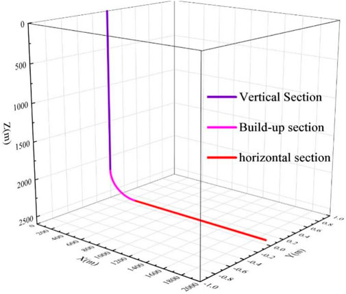
Figure 5. Wellbore trajectory.
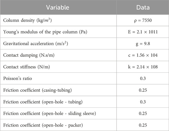
Table 1. Calculation parameters table.
Since the tubing string is a slender rod, it can be regarded as a beam element, while the wellbore wall is a discrete rigid body that is fixed. The mesh sensitivity analysis of the model is as follows: When the approximate global size of the wellbore wall mesh is less than 0.3 and the approximate global size of the tubing string mesh is less than 0.5, the calculated results for axial force and contact force are most accurate.
2.4 Validate the model
A scaled-down model for simulating the run-in process of a completion tubing string with packers for staged fracturing has been established. In this model, packers are replaced by nylon rods, precision steel tubes simulate tubing, and PMMA tube simulate the wellbore wall. Based on similarity theory (Xu, 1982; Ren et al., 2016), and considering geometric similarity, kinematic similarity, and dynamic similarity, the experimental setup has been designed to mimic the actual conditions in terms of size, shape, structure, motion, mechanical properties, and boundary conditions. A scaled-down completion tubing string run-in experiment was designed with a scale ratio of 10:1. The schematic diagram of the experimental setup is shown in Figure 6, and the experimental bench in Figure 7 includes the supporting components (Figure 7A), hydraulic cylinders (Figure 7B), tension-compression sensors (Figure 7C), paperless recorders (Figure 7D), PMMA tube (Figure 7E), nylon rods (Figure 7F), precision steel tubes simulating tubing (Figure 7G), and a combination of PMMA tube + nylon rod + precision steel tube (Figure 7H). The build-up section of the wellbore trajectory is simulated by pre-bending the wellbore.
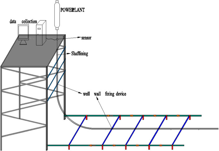
Figure 6. Diagram of the experimental setup.
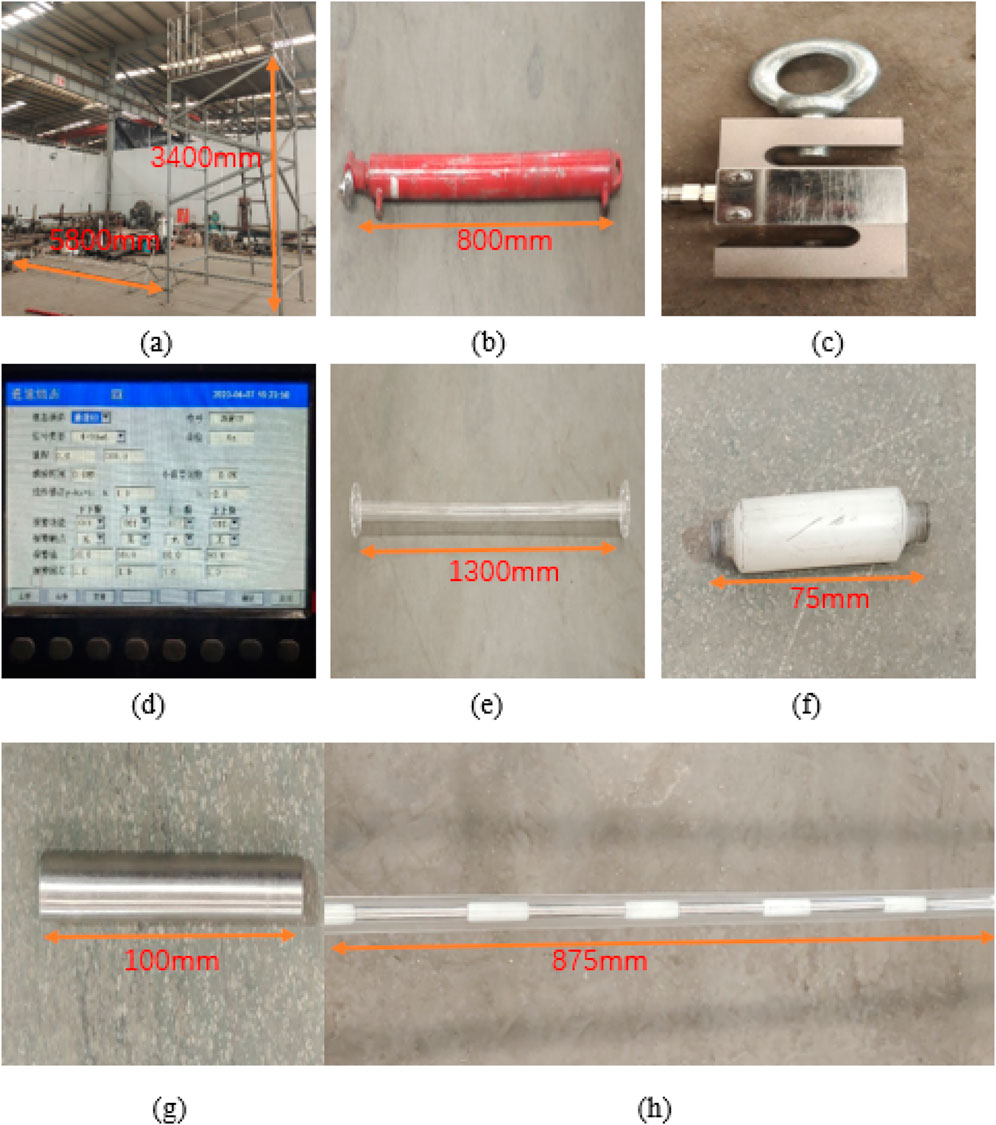
Figure 7. Experimental bench device. (a) Experimental stand. (b) Hydraulic cylinder. (c) Tensile transducer. (d) Paperless recorder. (e) PMMA tube. (f) Nylon rod. (g) Precision steel tube. (h) PMMA tube + nylon rod + precision steel tube.
By setting up an experimental bench, assembling the experimental equipment, connecting and zeroing the paperless recorder, we conducted an experiment to simulate the run-in process of a completion tubing string with packers in the build-up section of the wellbore, and obtained experimental data for extraction. Record the changes in traction force data for 5 times in each experiment. Select the data in the stable section as the calculation basis, and take the average value as the hook load.
Run-in experiments were conducted with simulated tubing strings of 6 stages (one stage consisting of tubing + sliding sleeve + tubing + packer), 9 stages, 12 stages, 15 stages, and 18 stages in both air and aqueous media environments. As the number of stages increased, the axial tensile force at the wellbore mouth decreased accordingly. According to Equations 3, 5 and Figure 3, as the number of stages increases, the self-weight of the tubing string in the BDE section increases in air, resulting in a decrease in
Figure 8 shows the comparison between experimental measurements and actual values in field applications. It can be seen from the figure that the ratio of experimental values to actual values is 1:10.5, which is close to the scaling factor of 1:10 (Figure 9).
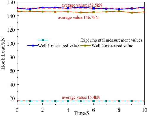
Figure 8. Comparison between experimental results and on-site measured values.
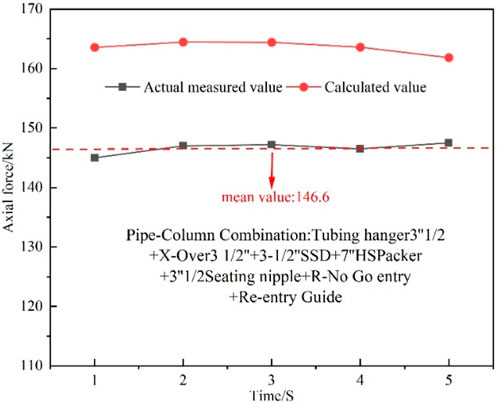
Figure 9. Comparison of measured and calculated values.
The comparison between the measured and calculated values of the axial force at the wellhead of Well HF007-S007H in Jidong is shown in. The measured value is 10% lower than the calculated value. The main reason for this situation may be that during the entire process of running in the tubing string, the actual working conditions in the open-hole section are complex. The friction coefficient between the same tubing and the open-hole section is not a fixed value, and the tubing string is more prone to buckling when passing through the open-hole section. Additionally, the scaling ratio of the simulation experiment is relatively large, and the error can be reduced by decreasing the scaling ratio of the tubing string. However, the experimental site needs to be over 300 m long, and the height of the experimental bench is approximately 80 m. The on-site conditions cannot meet the requirements of the experimental site.
Figure 10 presents the simulated hook load, with an average hook load of 163.56 KN. This finding is consistent with the field measurement data of the build-and-hold type well conducted by Maidla and Wojtanowicz (1987) in 1987, where the average hook load was measured to be 151 KN. All errors are within an acceptable range.
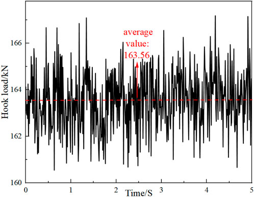
Figure 10. The hook load measured using a numerical model.
3 Analysis of mechanical characteristics of slim-hole completion tubing strings
3.1 The influence of packer outer diameter on the running-in resistance of completion tubing strings
Performing numerical analysis on the influencing factors and patterns of axial forces and contact forces acting on the completion string can facilitate the smooth lowering of the completion string. The outer diameter of the tubing string is a crucial factor affecting its running-in. With other conditions remaining unchanged, we investigated the impact of packers with different outer diameters (as shown in Table 2) on the resistance of the tubing string. The calculated influence pattern of the packer outer diameter on the setting resistance of the completion string is shown in Figures 11, 12.
Table 2. Packers with different outer diameters.
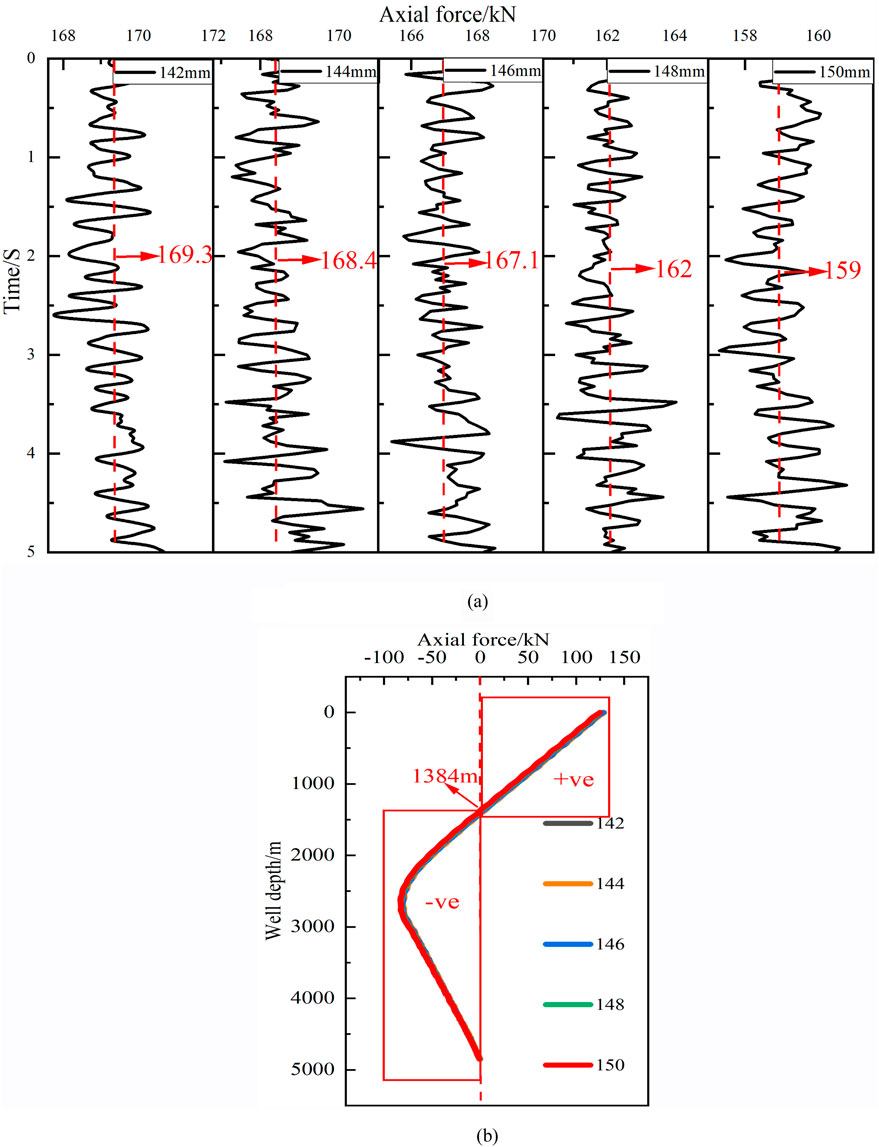
Figure 11. The influence of the packer outer diameter on the axial force of the packers. (a) Axial tension varies with the size of the packer. (b) The axial force along the well depth varies with the size of the packers.
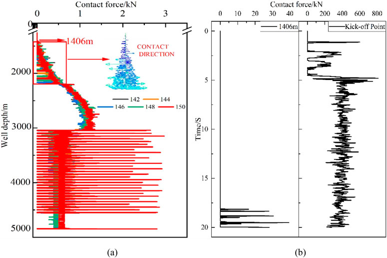
Figure 12. The influence of packer outer diameter on the contact force of the tubing string. (a) The contact force along the well depth varies with the size of the tubing string. (b) The contact force at 1406 m and the kick-off point varies with the size of the tubing string.
As shown in Figure 11A, as the packer size increases, the mean value axial tension at the wellhead decreases from 169.3 KN to 159 KN. This is because an increase in packer size results in a smaller gap between the packer and the wellbore wall, with more of the packer surface being covered by the wellbore wall. Consequently, the obstruction to the tubing string increases, causing the axial tension at the wellhead to decrease. In Figure 10B, the dashed line represents the neutral point (where neither tension nor compression is applied, and the axial force is 0 N; an axial force greater than 0 indicates the tubing string is in tension, and vice versa). It can be observed that as the well depth reaches 1384 m, the axial tensile force on the tubing string gradually converts into axial compression force (In the diagram, “+ve” represents axial tension and “-ve” represents axial compression.). As the diameter of the packer increases, the weight of the lower string also increases, causing a reduction in the axial force along the wellbore depth of the string and resulting in the neutral point shifting further upwards. After calculation, the neutral point has shifted up from 1416 m to 1384 m.
According to Figure 12A, when the tubing string with a packer outer diameter of 150 mm is run into the hole to a depth of 1,406 m, contact begins to occur. The contact force between the tubing string and the wellbore wall increases from 1406 m to the kick-off point. The direction of contact indicates that the tubing string is in contact with both the left and right sides of the wellbore wall, suggesting that buckling (subject to axial compression force) has occurred in this section. At a depth of 3000 m, the contact force of the tubing string experiences intermittent sudden increases. This is because the contact force here refers to the force acting on the packer, which is fully pressed against the wellbore wall in the horizontal section and weighs significantly more than the tubing. Therefore, the reaction force acting on the packer is also much greater than that on the tubing. When the packer outer diameter increases, the weight of the packer increases, leading to closer contact between the packer and the wellbore wall and a larger tubing contact force. The point where contact between the tubing string and the wellbore wall begins rises from 1454 m to 1406 m, resulting in an increase in the length of tubing string buckling. Figure 11B shows that the tubing string at a depth of 1406 m experiences intermittent contact at 18 s, while the tubing string at the kick-off point experiences intermittent contact at 1.1 s, earlier than at 1406 m. This indicates that buckling of the tubing string first occurs near the kick-off point. As the running-in process continues, the buckling extends from the kick-off point to the depth of 1406 m. In conclusion, it is recommended to select the Y221-142 packer for completion operations in small wellbores.
3.2 The influence of the open-hole section radius on the running-in resistance of the completion tubing string
Small wellbore diameters constitute a significant factor hindering the smooth running-in of the tubing string. With other conditions remaining unchanged, we designed open-hole section radii of 81.2 mm, 78.7 mm, 76.2 mm, 73.7 mm, and 71.2 mm to investigate the impact of different open-hole section radii on tubing string resistance. The calculated influence pattern of the completion string on the setting resistance under different open-hole radii is shown in Figures 13, 14.
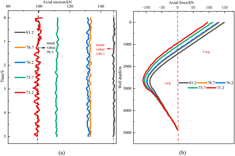
Figure 13. The influence of the open-hole section radius on the axial force of the tubing string. (a) The axial tension varies with the radius of the open-hole section. (b) The axial force along the well depth varies with the radius of the open-hole section.

Figure 14. The influence of the open-hole section radius on the contact force of the tubing string. (a) The contact force along the well depth varies with the radius of the open-hole section. (b) The contact force at 1358 m and the kick-off point varies with the radius of the open-hole section.
From Figure 13A, it can be observed that when the open-hole section radius is greater than 76.2 mm, the axial tension at the wellhead increases with the increase in the open-hole radius. When the open-hole radius is less than 76.2 mm, the axial tension at the wellhead decreases sharply with the decrease in the open-hole radius. This is because when the open-hole radius is greater than 76.2 mm, it falls outside the category of slim holes (A slim hole refers to a wellbore with a diameter of less than 6 inches Zhou et al., 1994), and the tubing string is less constrained by the wellbore wall in the open-hole section, allowing for a wider range of movement within the wellbore. When the open-hole radius is less than 76.2 mm, the wellbore wall fits more closely with the tubing string, resulting in greater obstruction and a sharp decrease in axial tension. Therefore, an open-hole section radius of 76.2 mm should be ensured for smoother running-in. According to Figure 12B, the neutral points of the frac-pack completion tubing string corresponding to the five radii (from smallest to largest) are 932 m, 1072 m, 1242 m, 1286 m, and 1436 m, respectively. It can be seen that as the open-hole radius increases, the neutral point shifts upward accordingly. The smaller the open-hole section radius, the higher the step at the junction between the kick-off section and the horizontal section, leading to a decrease in the axial tension transmission efficiency of the tubing string in the horizontal section. The accumulated axial compression force in the horizontal section will increase, and consequently, the maximum axial compression force on the tubing string will also increase.
As shown in Figure 14A, as the radius of the open-hole section decreases, the tubing contact force increases, with the most significant increase occurring in the kick-off section. When the radius of the open-hole section decreases, the global tubing in the open-hole section tightly fits against the wellbore wall, resulting in increased resistance for the lower tubing. Additionally, due to the presence of a step at the junction between the kick-off section and the open-hole section, the axial force transmission efficiency decreases (the higher the step, the lower the transmission efficiency), forcing the tubing in the kick-off section to transmit more axial force. This leads to more severe compression of the wellbore wall by the tubing in the kick-off section. As seen in Figure 13B, contact at the tubing kick-off point occurs before it does at 1358 m, indicating that buckling (compression due to axial force) first occurs near the kick-off point, similar to the influence pattern of changes in the outer diameter of the packer discussed earlier. However, the diameter of the open-hole section has a greater impact on the resistance encountered during tubing running-in. This is because the tubing in the open-hole section consists of packers, sliding sleeves, and tubing; the additional resistance due to increased packer size is less significant compared to the resistance caused by the close contact between the tubing, sliding sleeves, and the open-hole Section 3.3. The impact of different friction coefficients in the open-hole section on the running-in resistance of the completion tubing string. When the radius of the naked eye segment is less than 76.2 mm, there will be a significant increase in friction in the pipe column.
3.3 The influence of different friction coefficients of open-hole sections on the setting resistance of completion strings
The rocks commonly encountered in drilling are sedimentary rocks, and the types of sedimentary rocks vary among different rock formations, mostly including shale, sandstone, limestone, etc (Fernández et al, 2023; Fang et al., 2024). The friction coefficients on the surfaces of different rocks also differ. Generally speaking, the friction coefficient of the shale surface is relatively small. With other conditions remaining unchanged, the impact of designing different friction coefficients of 0.15, 0.2, 0.25, 0.3, and 0.35 in the open-hole section on the completion tubing string was analyzed. The calculated influence pattern of the setting resistance of the tubing string in different rock formations is shown in Figures 15, 16.
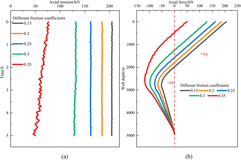
Figure 15. The influence of the friction coefficient of the open-hole section on the axial force of the tubing string. (a) The axial tension varies with the friction coefficient of the open-hole section. (b) The axial force along the well depth varies with the friction coefficient of the open-hole section.
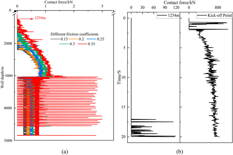
Figure 16. The influence of the friction coefficient of the open-hole section on the contact force of the tubing string. (a) The contact force along the well depth varies with the friction coefficient of the open-hole section. (b) The contact force at 1254 m and the kick-off point varies with the friction coefficient of the open-hole section.
As can be seen from Figure 15A, as the friction coefficient increases, the axial tension at the wellbore mouth decreases accordingly. When the friction coefficient reaches 0.35, the axial tension at the wellbore mouth decreases significantly over time. This is because the additional axial tension caused by the friction between the tubing string and the wellbore wall increases, resulting in a decrease in the axial force at the wellbore mouth. Figure 14B indicates that when the friction coefficient increases from 0.15 to 0.35, the axial tension and axial compression along the wellbore depth decreases, and the location of the neutral point shifts upwards from 1980 m to 480 m. With the increase in the friction coefficient, the Coulomb friction force acting on the tubing string increases, leading to greater resistance for the tubing string. The more significant the upward shift of the neutral point, the longer the length of the tubing string under axial compression.
As shown in Figure 16A, when the friction coefficient reaches 0.35, the tubing string begins to experience contact force at 1254 m. As the friction coefficient in the open-hole section increases, the Coulomb friction force generated by the contact between the tubing string and the wellbore wall during lowering also increases. Coulomb force is a major factor hindering the smooth lowering of the tubing string. An increase in Coulomb friction force makes relative motion between the tubing string and the wellbore wall more difficult, leading to more severe buckling of the tubing string and a corresponding increase in the contact force between the tubing string and the wellbore wall. Figure 15B indicates that the kick-off point of the tubing string experiences contact before 1254 m, and buckling (due to axial compression in this section) occurs first at the kick-off point. The contact force at the kick-off point shows an increasing trend, suggesting that the tubing string is pressed more tightly against the wellbore wall at this point, indicating more severe buckling of the tubing string at this location.
To sum up, the calculation results are in line with the expected results of the axial force distribution of the pipe string, that is, the axial force of the pipe string near the wellhead is tensile force. As the pipe string is lowered deeper into the well, the axial tensile force gradually changes into axial pressure. The greater the resistance experienced during the lowering process of the pipe column, the longer the length of buckling of the diameter section of the pipe column. The pipe string is most likely to buckle where it is subjected to the maximum axial pressure, which is mostly near the Kick-off Point This is mainly because the increase in friction coefficient and pipe string size leads to greater frictional resistance on the pipe string. The collision between the pipe string and the wellbore at the kick-off point becomes more intense, making the pipe string more prone to buckling at this location. During the construction, the strength of other sections of the pipe string remains unchanged, and the strength of the pipe string near the Kick-off Point should be focused on strengthening to prevent buckling. The strength of the pipe string at the kick-off point can be enhanced by increasing the thickness of the pipe string and using higher-strength materials at this location. The findings of this study are not only applicable to small wellbores but also to conventional horizontal wells. And it can save the cost of replacing and repairing the pipe column.
4 Conclusion
Addressing the difficulty of lowering the completion tubing string in the open-hole section during staged fracturing in small-diameter wellbores with large-sized tubing strings, this study analyzes the factors and patterns influencing the axial and contact forces acting on the completion tubing string during lowering, as well as the locations prone to buckling throughout the wellbore. The following conclusions are drawn:
(1) An experimental setup was constructed based on the principle of scaling and experiments were conducted to simulate the lowering of tubing strings in different stages, with varying kick-off rates and in different media, validating the accuracy of the results obtained from the three-dimensional finite element model.
(2) The impact of different packer outer diameters on the axial tension at the wellbore mouth, axial tension and axial compression along the wellbore depth, and contact force along the wellbore depth of the completion tubing string was compared. It was found that as the packer outer diameter increases, the neutral point shifts upwards, resulting in an increase in the length of the tubing string under axial compression. The tubing string first comes into contact with and buckles against the wellbore wall near the kick-off point, and buckling occurs upwards from the kick-off point.
(3) The impact of different open-hole radii on the resistance of the completion string was compared. It was found that as the open-hole radius decreases, the axial tension at the wellhead of the tubing string decreases accordingly, and both the axial tension and axial compression along the well depth also decrease. Meanwhile, the contact force increases, with the most significant increase occurring in the kickoff section. Compared to changes in packer radius, changes in the diameter of the open-hole section have a greater impact on the setting resistance of the tubing string.
(4) The trends and patterns of axial and contact forces in tubing strings with different friction coefficients were compared. It was found that as the friction coefficient of the tubing string increases, the resistance during lowering also increases, leading to a significant decrease in the axial tension at the wellbore mouth. The contact force along the wellbore depth increases notably, and the degree of buckling in the tubing string near the kick-off point worsens over time. It is recommended to enhance the strength of the pipe string at the kick-off point during operations, such as by increasing the wall thickness at this critical section. This reinforcement approach can effectively reduce pipe string maintenance frequency, thereby achieving the objective of lowering construction costs.
Data availability statement
The original contributions presented in the study are included in the article/supplementary material, further inquiries can be directed to the corresponding author/s.
Author contributions
LD: Writing – review and editing. WY: Data curation, Software, Writing – original draft, Writing – review and editing. HL: Methodology, Writing – review and editing. BL: Formal Analysis, Investigation, Writing – review and editing. XZ: Project administration, Writing – review and editing.
Funding
The author(s) declare that financial support was received for the research and/or publication of this article. This research was supported by National Natural Science Foundation (52204050), Sichuan science and technology program (25JBGS0034).
Conflict of interest
Author HL was employed by CNPC Bohai Petroleum Equipment Manufacturing Co., Ltd.
The remaining authors declare that the research was conducted in the absence of any commercial or financial relationships that could be construed as a potential conflict of interest.
Generative AI statement
The authors declare that no Generative AI was used in the creation of this manuscript.
Publisher’s note
All claims expressed in this article are solely those of the authors and do not necessarily represent those of their affiliated organizations, or those of the publisher, the editors and the reviewers. Any product that may be evaluated in this article, or claim that may be made by its manufacturer, is not guaranteed or endorsed by the publisher.
References
Al-Khaldi, M., Al-Saadi, D., Al-Ajmi, M., Dutta, A., Elafify, I., Farhi, N., et al. (2021). “Double casing Exit for side-track to commingle two borehole sizes based sections in one slim shot to well TD,” in Paper presented at the SPE Middle East oil & gas show and conference, event canceled. doi:10.2118/204881-MS
Alzahabi, A., Trindade, A. A., and Kamel, A. (2024). Optimizing estimated ultimate recovery in horizontal wells through data-driven analytics. Geoenergy Sci. Eng. 239, 212901. doi:10.1016/j.geoen.2024.212901
Amir, S., and Ahmed, E. (2021). Well design optimization through the elimination of intermediate casing string. J. King Saud Univ. - Eng. Sci. doi:10.1016/j.jksues.2021.01.002
Amir, S., Ahmed, E., and Adel, S. (2021). Implementation of a novel eccentric dog leg reamer in oil well drilling. J. Petroleum Explor. Prod. 11 (3), 1199–1209. doi:10.1007/s13202-021-01096-3
Dong, W. (2018). “Research on the safety analysis of wellbore string column in steam-injected thick oil hot recovery wells PhD,”. East China: University of Petroleum China. Dissertation. doi:10.27644/d.cnki.gsydu.2018.000049
Fang, X., Wang, Y., Zhang, Y., and Li, F. (2024). Experimental investigation on identification of lithologies and layered rock interface based on drilling vibration response. Geoenergy Sci. Eng. 233, 212556. doi:10.1016/j.geoen.2023.212556
Fernández, A., Sanchidrián, J. A., Segarra, P., Gómez, S., Li, E., and Navarro, R. (2023). Rock mass structural recognition from drill monitoring technology in underground mining using discontinuity index and machine learning techniques. Int. J. Min. Sci. Technol. 33 (5), 555–571. doi:10.1016/j.ijmst.2023.02.004
Galasso, S., Santelli, L., Zambetti, R., and Giusteri, G. G. (2025). Simulation of drill-string systems with fluid–structure and contact interactions in realistic geometries. Comput. Mech. 75, 1165–1189. doi:10.1007/s00466-024-02555-4
Gao, D. L., Huang, W. J., Liu, Y. S., and Tan, L. (2020). “A new species of the genus Drexler (Coleoptera, Staphylinidae, Staphylininae),” in Several research progresses in drilling column mechanics and casing wear prediction. Petroleum Pipe and Instrumentation. (Beijing: Tongfangzhiwang Technology Co., Ltd). 04, 1–9. doi:10.19459/j.cnki.61-1500/te.2020.04.001
Gao, D. L., and Huang, W. K. (2021). Progress of some research on downhole tubular column mechanics and control methods. Adv. Mech. Beijing: Tongfangzhiwang Technology Co., Ltd. (03), 620–647.
Li, G., Sun, G., Lin, G. H., Yue, L., Cup, Y., Zhang, Q., et al. (2023). Submodeling method for wear prediction after buckling of pressurized tubular column in wellbore. Mech. Strength. Beijing: Tongfangzhiwang Technology Co., Ltd. (05), 1181–1191. doi:10.16579/j.issn.1001.9669.2023.05.023
Lian, Z., Lin, T., Liu, J., Le, B., Chen, J., and Zhang, J.-C. (2006). Mechanical-mathematical modeling of horizontal well completion string column. Nat. Gas. Ind. Beijing: Tongfangzhiwang Technology Co., Ltd. (07), 61-64+153–154.
Lian, Z. H., Shi, T. H., and Han, J. Z. (2002). Simulation study of friction coefficient and axial displacement of expanding casing. Pet. Machinery. Beijing: Tongfangzhiwang Technology Co., Ltd. 01, 1–3+7-3.
Lian, Z. H., Zhang, Y., Zhao, X., Ding, S. D., and Lin, T. J. (2015). Establishment and application of mechanical and mathematical modeling of multi-stage fractured tubular column in horizontal wells. Nat. Gas. industry. Beijing: Tongfangzhiwang Technology Co., Ltd. 01, 85–91.
Maidla, E. E., and Wojtanowicz, A. K. (1987). Field comparison of 2-D and 3-D methods for the borehole friction evaluation in directional wells. SPE Annual Technical Conference and Exhibition. SPE, 3310–3663.
Ren, F. S., Liu, J. H., Li, Y., and Wang, B. J. (2016). Development of horizontal pressurized drilling column test device based on similarity theory. Pet. Mach. (04), 12–16+22. doi:10.16082/j.cnki.issn.1001-4578.2016.04.003
Shan, F., Xian Duan, Y., Zhou, J., Wang, D., Hong Ji, X., Zhou, Z., et al. (2024). “Preliminary study on oil test and completion technology of over 9000 m deep wells—taking guole X well as an example,” in Proceedings of the international field exploration and development conference 2023. Editor J. Lin (Singapore: Springer Series in Geomechanics and Geoengineering. Springer). IFEDC 2023. doi:10.1007/978-981-97-0256-5_11
Shan, F. (2024). “Research and application of special completion technology in complex wellbore conditions of ultra-deep carbonate reservoirs,” in Proceedings of the international field exploration and development conference 2023. Editor J. Lin (Singapore: Springer Series in Geomechanics and Geoengineering. Springer). IFEDC 2023. doi:10.1007/978-981-97-0256-5_40
Shokry, A., Salem, B., and Elkatatny, S. (2024). Evaluation of using micronized saudi calcite in ilmenite-weighted water-based drilling fluid. Sci. Rep. 14 (1), 12777. doi:10.1038/s41598-024-63839-6
Yuhui, Z., Kaimin, Z., and Shen, Z. (1994). Small hole drilling technology. Petroleum Drill. Prod. Technol. (02), 16–24+105.
Zhu, X. H., Li, B., Li, K., Zhu, K.-L., Hu, C. C., and Chang, X. J. (2019). A fast solution method for dynamic drag torque of drilling column in large inclined wells. J. Petroleum. Beijing: Tongfangzhiwang Technology Co., Ltd. (05), 611–620.
Keywords: open-hole section, small wellbores, mechanical characteristics, completion string, buckling of pipe string
Citation: Dong L, Yang W, Li H, Li B and Zhu X (2025) Mechanical characteristics analysis of the downhole completion string in the open hole section of a small wellbore. Front. Mech. Eng. 11:1554211. doi: 10.3389/fmech.2025.1554211
Received: 01 January 2025; Accepted: 12 May 2025;
Published: 02 July 2025.
Edited by:
Guo Xiang, Technion Israel Institute of Technology, IsraelReviewed by:
Madhu Puttegowda, Malnad College of Engineering, IndiaSeyed Borhan Mousavi, Texas A and M University, United States
Milan Bukvic, University of Kragujevac, Serbia
Zhanghua Lian, Southwest Petroleum University, China
Copyright © 2025 Dong, Yang, Li, Li and Zhu. This is an open-access article distributed under the terms of the Creative Commons Attribution License (CC BY). The use, distribution or reproduction in other forums is permitted, provided the original author(s) and the copyright owner(s) are credited and that the original publication in this journal is cited, in accordance with accepted academic practice. No use, distribution or reproduction is permitted which does not comply with these terms.
*Correspondence: Liangliang Dong, ZGxsMTgxQDE2My5jb20=; Weijian Yang, OTA5NzQ2ODk3QHFxLmNvbQ==; Bo Li, bGlibzkwMTEzQDE2My5jb20=; Xiaohua Zhu, emh1eGhAc3dwdS5lZHUuY24=
†ORCID: Liangliang Dong, orcid.org/0000-0002-1665-0636; Weijian Yang, orcid.org/0009-0009-2200-3388