Aerodynamic characteristics of a delta wing aircraft under ground effect
 Arash Shams Taleghani*
  Arsalan Ghajar
- Aerospace Research Institute, Ministry of Science, Research and Technology, Tehran, Iran
The main objective of this study is to investigate the impact of ground effects on the aerodynamic coefficients of a delta wing aircraft model. Since the flow on the delta wing exhibits vortical flow inherently, it is crucial to examine the influence of ground effects under these conditions. An experimental study was conducted to enhance understanding of the aerodynamic behavior of an aircraft model incorporating a delta wing-body-vertical tail. Experiments were conducted in a subsonic wind tunnel with a test section measuring 2.8 m × 2.2 m. Measurements were taken using a sting type balance to determine the aerodynamic forces and moments. All experimental tests were performed at a Reynolds number of 1.5 × 10⁶, with the specific aim of examining and identifying the influence of the ground on aerodynamic coefficients. To investigate how ground effect affects the aerodynamic performance of the model, a fixed plate with an adjustable height was placed underneath it. The distance between the model and the ground was varied, and resulting data indicated that increased proximity to the ground improved longitudinal static stability. The results revealed that the presence of the ground plane resulted in a 6% increase in the maximum lift coefficient. Meanwhile, the lift increases around 25% due to ground effects at an angle of attack of 14° as it approaches the ground. The lift coefficient was enhanced across all angles of attack, while the induced drag coefficient decreased, resulting in an overall increase in aerodynamic efficiency. The lift curve slope saw a 16.9% increase when the model’s height from the ground plane was less than half of the wing span. As the height decreased further, the aerodynamic center shifted backward, leading to an increase in longitudinal static stability. The rolling moment and yawing moment coefficients becomes unstable at angles of attack above 30°.
1 Introduction
During the past decade, airplane aerodynamic designers have concentrated on enhancing the lift coefficient (Mirzaei et al., 2012; Taleghani et al., 2012; Salmasi et al., 2013; Mohammadi and Taleghani, 2014; Abdolahipour, 2023) and lowering the drag coefficient (Albers et al., 2019; Atzori et al., 2020; Rodriguez et al., 2020; Kornilov, 2021; Fahland et al., 2023) through active flow control methods in cruise phase. They have also aimed to improve the aerodynamic coefficients on high-lift devices during takeoff and landing phases (Abdolahipour et al., 2021; Abdolahipour et al., 2022a; Abdolahipour et al., 2022b). Despite the importance of the issue of ground effect during takeoff and landing, recent years have seen fewer research results published, possibly due to the short duration of exposure to ground effect. A more comprehensive investigation is necessary to fully understand the impact of ground effect on aircraft performance in these critical phases of flight. When an aircraft flies at a low altitude, the airflow between the airplane and the ground aligns parallel to the surface, causing noticeable variations in the airplane’s aerodynamics from flying at higher altitudes. This phenomenon is referred to as the ground effect. The ground effect has a significant impact on conventional airplanes during the landing and take-off phases, as well as on ground effect airplanes during horizontal flight. A clear comprehension of ground effects is crucial for advancing modern conventional airplane control systems, designing landing gears, and creating high-lift devices. In general, when an airplane is near the ground, the wing produces a greater amount of lift. The examination of ground effects on a wing can be separated into 2D and 3D effects. The ground induces a high-pressure distribution on the lower surface of a two-dimensional airfoil when the angle of attack is positive. This results in an increase in lift for the airfoil. A three-dimensional wing at a positive angle of attack also experiences a decrease in downwash angle and induced drag.
In a wind tunnel experiment, Ahmed et al. (Ahmed et al., 2007) studied the performance of a NACA4412 airfoil under ground effect conditions. The outcomes revealed that low angles of attack (α < 4°) led to reduced lift near the ground. Conversely, the lift increased in close proximity to the ground for angles of attack between 4° and 8°. Higher angles of attack result in greater lift near the ground plane due to the increased pressure on the lower surface of the airfoil. Ahmed and Sharma (Ahmed and Sharma, 2005) conducted a study on the NACA 0015 airfoil in ground effect. The study found that the aerodynamic characteristics were significantly influenced by both the angle of attack and the distance from the ground. Additionally, Zerihan and Zhang (Zerihan and Zhang, 2000) conducted a wind tunnel experiment on the Tyrrell-02 airfoil, which is an inverted airfoil with a high camber, to investigate its ground effect. The researchers observed a gradual increase in downforce as the distance from the ground plane decreased, reaching a maximum value before decreasing. An analysis of the aerodynamic and stability properties of airfoils under extreme ground effects was conducted by Nirooei (Nirooei, 2018). At low Reynolds numbers, ground effects were studied around the NACA 4415 airfoil according to He et al. (He et al., 2018). They used this data to investigate the influence of ground effects on the aerodynamic performance of the airfoil. The study, utilizing both numerical and theoretical methods, demonstrated the influential role of the ground on both primary and secondary instabilities of the separated flow surrounding the airfoil in low Reynolds number conditions.
A numerical simulation was performed to assess the aerodynamic features of 2D smart flaps while considering the ground effect (Djavareshkian et al., 2011). A computational simulation (Qu et al., 2014) was also performed to study the impact of dynamic ground effects on a NACA 4412 airfoil during the landing phase. The analysis revealed that at higher altitudes, the lift experienced in dynamic ground effect (DGE) remains constant despite the decrease in altitude, and is equivalent to the lift in static ground effect (SGE). On the other hand, the lift of DGE increases rapidly as the height decreases in the small height region. Furthermore, it is substantially higher than the lift in SGE with the same angle of attack. Gratzer and Mahal (Gratzer and Mahal, 1971) conducted an analysis of the aerodynamics of an STOL aircraft in ground effect through theoretical analysis and wind tunnel experiments. They found that as the height from the ground plane decreased, the slope of the lift curve decreased as well as the pressure on the upper surface. For the 3D study on ground effect, the focus has been on the aerodynamics of wingtip vortices. Chawla et al. (Chawla et al., 1990) conducted an aerodynamics experiment on a wing with an NACA4415 airfoil and aspect ratio of 2.33, utilizing a grounded plane. Their research revealed that implementing endplates improved lift at low heights from the ground plane. Lee (Lee, 2002) carried out an experimental examination of the motion of wingtip vortices of a rectangular wing in the ground effect. The study findings indicate that the presence of the ground plane causes a deceleration of downward vortices' motion and their outward motion towards the spanwise direction as a result of the ground effect.
In a wind tunnel experiment performed by Harvey and Perry (Harvey and Perry, 1971), they examined the trajectory of wingtip vortices in ground effect. Their results indicate that the vortices descended towards the ground initially before rebounding downstream. Furthermore, Dakhrabadi and Seif (Tavakoli Dakhrabadi and Seif, 2016) studied the aerodynamic properties of the compound wing-in-ground effect with both the main and outer wings. The study demonstrated that repositioning the outer wing towards the trailing edge of the main wing enhanced static height stability, leading to a decrease in tail area. In a study conducted by Rojewski and Bartoszewicz (Adam and Bartoszewicz, 2017), the impact of wing-in-ground effects was assessed on the lift coefficients of airplanes and the downforce coefficients of cars. Positive angles of attack result in a higher lift coefficient, while negative angles of attack result in a lower lift coefficient. Computational simulations were carried out by Sereez et al. (Sereez et al., 2017; Sereez et al., 2018) using CFD methods to study the aerodynamic features of the Common Research Model (CRM). This model represents a typical transport airliner in proximity to the ground. Wang (Wang, 2005) discovered significant changes in lateral-directional modes when a slender object operates close to the ground. Their study examined the body’s lift and pitching moment relative to its distance from the ground plane. Their results indicate that lift decreases and nose-up pitching moment increases as the distance from the ground decreases.
The ground effect was investigated by Deng (Deng, 2017) using a simulation of a three-dimensional wing-body configuration. Computations were conducted for the DLR-F6 wing-body in unbounded flow, and compared with experimental data to verify the accuracy of the simulation approach. As the wing body’s height from the ground decreased while maintaining a fixed angle of attack, researchers observed an increase in lift, a decrease in drag, and an increase in nose-up pitching moment. Similarly, Deng et al. (Deng et al., 2017) studied the aerodynamics of the DLR-F6 wing body in unbounded and ground effects. It was discovered that increasing the angle of attack in the ground effect amplified the blockage effect while reducing the nose-up pitching moment. The Delayed Detached Eddy Simulation and Spalart-Allmaras turbulence model were used to investigate the aerodynamics and flow physics of a close-coupled canard configuration with a sharp leading edge in static ground effect (Qin et al., 2017), as well as a 65° sweep delta wing with a sharp leading edge in both static and dynamic ground effect (Qin et al., 2015; Qin et al., 2016).
In wind tunnel studies of ground effects, static ground effect is the most frequently used technique. This involves employing a stationary model at different heights above the ground plane to simulate the behavior of an aircraft flying at a consistent altitude near the ground. The static data obtained facilitates the simulation of an aircraft’s behavior when flying at a uniform altitude close to the ground. To replicate the rate of descent of a descending airplane at a specific altitude, a wind tunnel can be utilized. The technique involves using a model that moves towards either a stationary or a moving ground plane, commonly referred to as dynamic ground effect (Chang and Muirhead, 1985; Lee et al., 1987a; Kemmerly et al., 1988; Lee et al., 1989; Paulson et al., 1990).
The results indicate that defining the ground effects numerically is complex due to the significant and variable influence of the ground effect when the height is below a certain threshold. These effects are non-linear; for instance, the increase in lift force is non-linear when the height is less than half of the wing span, and these variations differ among different aircraft. To predict and study the ground effects, analytical software is commonly employed (McDonnell Douglas Corporation and USAF Stability and Control DATCOM, 1960). This software utilizes flight data, equations, and tables to forecast control and stability characteristics.
Recently, Shams Taleghani et al. (Taleghani et al., 2020) conducted a study to examine how the ground affects aerodynamic coefficients in different situations involving the angle of attack and horizontal tail angle. Their research primarily focused on evaluating the performance of the horizontal tail by observing changes in lift, drag, and pitching moment coefficients under various conditions, including ground effect and out-of-ground effect.
Limited experimental results exist for the ground effect of delta wings, mainly focusing on airplane-like configurations (Kemp et al., 1966; Rolls and Koenig, 1966; Lockwood and Phillips, 1968; Corsiglia et al., 1969; Baker et al., 1970; Snyder et al., 1970; Katz and Levin, 1984). This study aims to experimentally evaluate the static aerodynamic properties of a model with a 60° swept delta wing. The model includes a fuselage and vertical tail, both positioned close to and above the ground surface.
2 Experimental setup
The experiments were carried out at the National Low-Speed Wind Tunnel, which features an open test section. The rectangular test section measures 2.2 m × 2.8 m × 4 m in dimensions. The tunnel is equipped with a fixed-pitch axial-flow fan powered by a 1.2 MW electric motor, with a diameter of 4.5 m. The rotational speed of the fan can be adjusted between 60 and 560 rpm to control the airflow velocity in the test section, ranging from 10 m/s to 70 m/s. To ensure a uniform and low turbulence flow, the tunnel incorporates a six-to-one contraction following a settling chamber. The settling chamber includes one honeycomb and two metal screens. The tunnel was calibrated to ensure that the flow parameters, including turbulence level, flow uniformity, and flow angularity, were within acceptable limits for this type of wind tunnel. To measure the turbulence level of the flow in the test section and test section airflow non-uniformity in velocity, a thermal anemometer (specifically, the DANTEC 55P11 one-dimensional hot wire probe) was used. Using a traverse mechanism, the whole area is scanned by a hot wire probe at different test section flow velocities. Hot wire probe measures turbulence intensity using flow velocity fluctuations measurement. The turbulence intensity at the center of the test section remains below 0.13% for velocities exceeding 35 m/s. At a test section airflow velocity of 50 m/s, the turbulence intensity remains below 0.2%, except in regions near the free jet boundary. The test section airflow experiences a non-uniformity of less than 0.2% in velocity. The flow angle in the test section, at the same airflow velocity, was approximately 0.3°. The velocity of the airflow in the test section is determined using a pitot-static tube placed on one of the side walls. This tube is connected to both the data acquisition system and a precise differential pressure transducer. The transducer has an accuracy of 0.05% for pressure readings. The maximum error in measuring the flow velocity measured by pitot-static tube is 0.1 m/s.
A 6-component internal strain gauge balance is used to measure the aerodynamic forces and moments on the model. The maximum range of linear loading for lift, drag and side forces is 150 kg, 50 kg and 150 kg respectively, and the pitching moment, rolling moment and yawing moment are all 15 kg-m. This balance is attached to the model, which is connected to the sting mounted on the vertical and L-shaped rotated struts of the rig. A vertical strut is driven by an electric motor and gearbox located on the rotating floor plane of the wind tunnel test section, which generates the motion of the model. To conduct static tests, the model and the internal balance are placed on a test stand. The angle of attack and sideslip angle can be adjusted manually or in a pre-planned manner using potentiometers. This experimental setup covers a range of −10°–40° for the model’s incidence. The setup is mounted on a special platform (turntable) with a diameter of 2.0 m, installed on the wind tunnel test section’s floor plane. By rotating the turntable, the mean sideslip can be changed based on the orientation of the aerodynamic model. The wind tunnel’s working section turntable rotation allows for investigations of sideslip angles from −90° to +90°. All of the experiments were conducted at zero sideslip angle. This experimental setup enables the conduct of conventional steady experiments.
High-speed analog-to-digital converters are used to measure the strain gauge balance signals. A 16-channel data acquisition system processes all forces and moments, as well as the angles of attack and sideslip angles, along with the dynamic pressure. These measurements are then converted to their corresponding physical quantities using calibration coefficients. The data is acquired at a frequency of 30 kHz for a duration of 10 s at each mean angle of attack. This acquisition time allows for flow stabilization, while the sampling rate is sufficient to capture the unsteady flow phenomena.
The present study utilized a model consisting of a delta wing combined with a body and vertical tail, where the wing was fixed in the middle position. The aircraft’s wing featured a delta-shaped design with an aspect ratio of 2.31 and a leading edge sweep of 60°. The upper surface of the wing was flat, while the leading and trailing edges were beveled and sharp, forming a 20° angle between the lower and upper surfaces. The fuselage was cylindrical in shape with an ogive nose. It consisted of two sections: a tangent ogive nose with a semi-apex angle of 20°, and a constant diameter section measuring 0.833 m in length. The fuselage had a total length of 1.092 m and a diameter of 0.1 m. The wing was constructed from a flat plate section. The wing reference area was 0.433 m2 and the aerodynamic mean chord was 0.577 m. The pitching moment of the model was measured at 25 percent of the mean aerodynamic chord. Figure 1A provides a schematic representation of the 60° delta wing-body-tail model. Figure 1B shows the model normal and inverse positions. At inverse position the model is rotated 180° around its body axis. The dimensions of the model were determined based on specific criteria, including the dimensions of the wind tunnel test section and the maximum allowable loads on the balance. In order to meet the limitations of the wind tunnel test section, the wing span of the model must be less than 0.80 times the width of the test section, and the frontal area of the model must be less than 7 percent of the test section area to minimize any effects from the test section walls. Based on these criteria, the model’s wing span is 1.0 m, which is less than 0.80 times 2.8 m (the width of the test section). Additionally, the model’s frontal area at an angle of attack of 40° is calculated as follows: Wing area × sin 40° = 0.433 × 0.6427 = 0.2783 m2. Considering the test section area is approximately 6.0 m2, the model’s blockage ratio (0.2783/6.0 × 100) is approximately 4.6%, which is less than the allowed 7%. Regarding the maximum allowable loads on the balance, the normal force must be less than 150 kg. At a velocity of 50 m/s, the normal force is determined by 0.5× density × velocity2 × wing area × maximum normal force coefficient (0.5 × 1.1×502 × 0.433×1.5). This calculation results in a normal force of 893 N, which is equivalent to 91 kg, and is less than the allowed 150 kg.
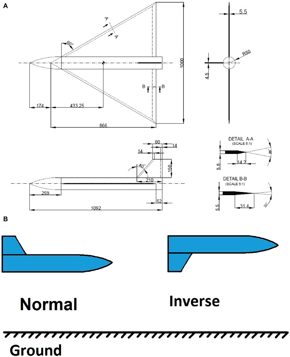
FIGURE 1. Schematic of (A) 60° delta wing-body-tail model (dimensions in mm) and (B) Model at normal and inverse positions.
The investigation of the ground effect utilized a generic delta wing aircraft configuration derived from a delta wing-body setup. The delta wing-body-tail model was affixed to a sting balance, allowing for vertical transverse movement relative to the model. The wind tunnel test section had a rectangular cross-section, which was effectively reduced by the ground plane. Throughout the test, a constant airspeed of 50 m/s was maintained, corresponding to a Reynolds number of 1.5 × 10⁶. The delta wing model featured a cylindrical center body connected to a six-component sting balance. To analyze the impact of ground effects on the longitudinal characteristics of the delta wing-body-tail model, the model was positioned at various heights above the ground simulator plate. The model was secured on a sting-type support stand in the center of the wind tunnel test section, while the ground plane was adjusted vertically. Figure 2 depicts the installation of the delta wing model on the ground simulation stand. The six components of the strain-gauge balance, which were installed on the stand, were capable of measuring all aerodynamic forces and moments.
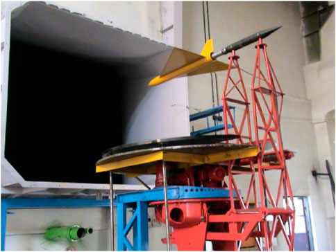
FIGURE 2. Delta wing-body-tail model installation on ground simulation stand.
Two separate potentiometers on this stand are used to measure the angle of attack and sideslip angle. The maximum error in measuring the angles of attack and sideslip angle is 0.1°. This stand incorporates a fixed plate under the central area of the test section in order to simulate the ground plane. The model was placed on the stand and tested at various ground elevations in this investigation. The measured data is compared with two basic models that were previously used for the experimental study. The 60° delta wing model was tested by Chang (Chang and Muirhead, 1987), Wentz (Wentz, 1968), and Pal Hung Lee et al. (Lee et al., 1987b), while the 1/48 scale model of the F-106 was also used.
3 Results
Delta wing-body-tail longitudinal aerodynamic coefficients are shown in Figure 3. These results are presented for conditions where the ground plane is absent. The tests were conducted in six runs, with three runs in the normal position and three runs in the inverse position of the model. The measured data demonstrate good repeatability. Model tests in normal and inverse position have been used to determine the flatness of the flow. Based on the calibration of equipment, the measurement error of the lift, drag, and side forces are 0.13%, 0.3% and 0.4% respectively and for the pitching moment and yawing moments are 0.4%, and for the rolling moment is 0.7%. To ensure the acceptable reliability of the used data, the uncertainty of the obtained data has been calculated based on the variance analysis method. Both systematic error and precision are considered in these calculations. Sensor errors, changes in flow density and velocity, changes in static pressure, data acquisition system errors, pressure sensor errors, etc. Have been investigated. The uncertainty value of the longitudinal static aerodynamic coefficient has been calculated using the results of 6 individual tests. The uncertainty of lift coefficient, drag coefficient and pitching moment coefficient at a low angle of attack is 0.0051, 0.009 and 0.0025 respectively and at a high angle of attack is 0.0160, 0.0105 and 0.0019 respectively.
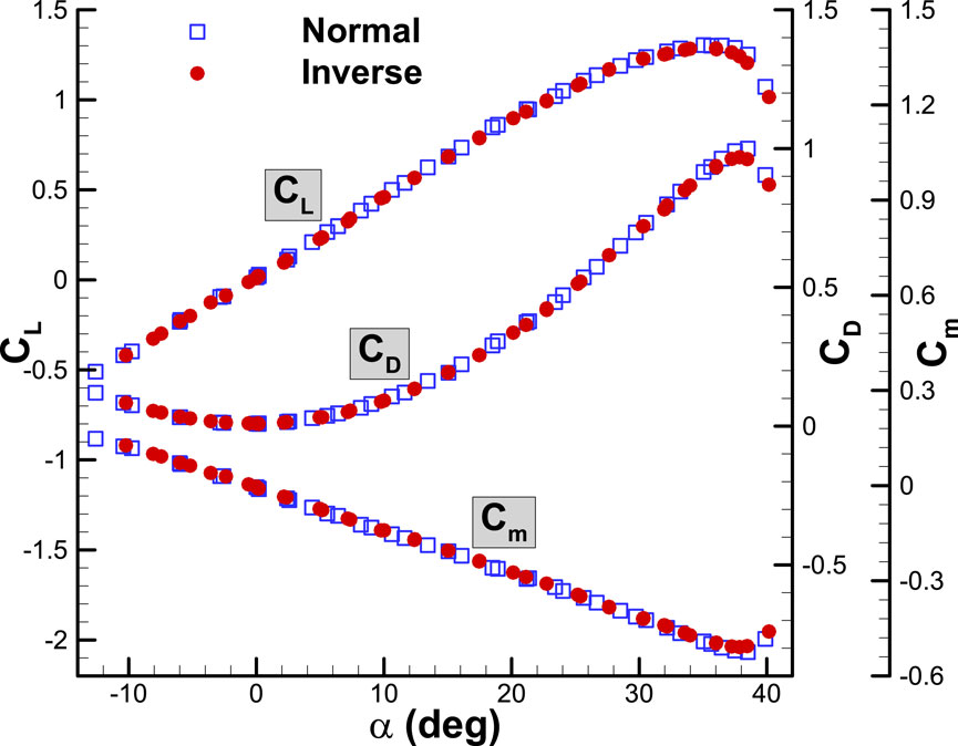
FIGURE 3. Variation of aerodynamic coefficients with angle of attack for the aircraft model without the ground plane.
In Figure 3, the lift curve slope at the linear region of the angle of attack is 0.0455 per degree. The curve remains linear up to an angle of attack of 25° but becomes nonlinear at higher angles due to the forward movement of the vortex bursting location. The angle of attack at which the stall occurs is approximately 35°. The maximum lift coefficient is 1.3. The variation of the drag coefficient with the angle of attack shows the minimum drag coefficient is 0.0095. At an angle of attack greater than 35°, a stall occurs due to full vortex bursting over the delta wing. As a result, the lift force decreases, leading to a decrease in the induced drag (drag caused by lift) and ultimately reducing the total drag. The pitching moment coefficient is measured from 0.25 MAC. The pitching moment coefficient curve remains linear up to the stall angle of attack, with a slope of −0.0135 per degree. The curve slope with respect to the lift coefficient is −0.3, indicating that the aerodynamic center of the entire configuration is located at 0.55 MAC. Figures 4, 5, 6 display the variation of the lateral and directional aerodynamic coefficients (side force, yawing, and rolling moment) with the angle of attack, specifically at zero sideslips. Figure 4 displays the curve of the side force coefficient relative to the angle of attack at zero-degree sideslip. The side force coefficient is negligible at low angles of attack, up to approximately 20°, due to the absence of sideslip. As the angle of attack grows, the value of the side force coefficient increases, owing to the unstable vortex flow at high angles of attack. The positions of vortex bursting on the right and left wings are not consistent at a certain angle of attack, resulting in different lift forces on each side due to variations in vortex strength. The positions of vortex bursting on the right and left wings are not consistent at a certain angle of attack, resulting in different lift forces on each side due to variations in vortex strength. Consequently, the rolling moment coefficient becomes unstable at high angles of attack. Figure 5 displays the rolling moment coefficient graph with respect to the angle of attack at a sideslip angle of zero degrees. The same phenomenon is observed in the yawing moment coefficient, as demonstrated in Figure 6. This can be attributed to the instability of vortex bursting at high angles of attack. Beyond an angle of attack of 30°, the flow fields on the wing-body-tail combination become asymmetric.
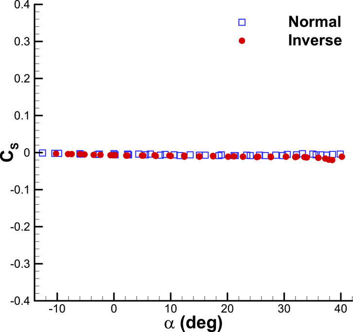
FIGURE 4. Variation of side force coefficient with angle of attack for the aircraft model without the ground plane.
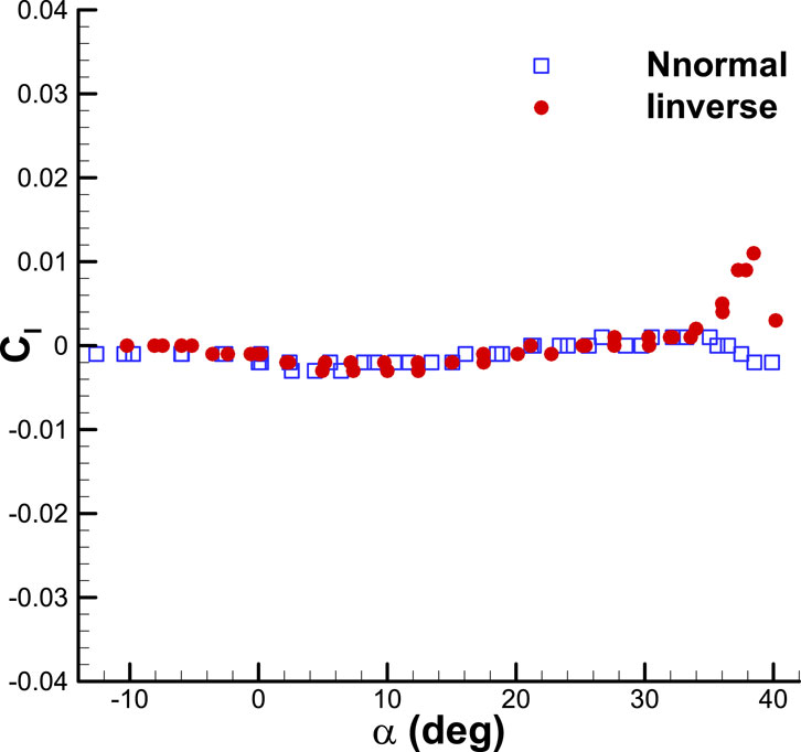
FIGURE 5. Variation of rolling moment coefficient with angle of attack for the aircraft model without the ground plane.
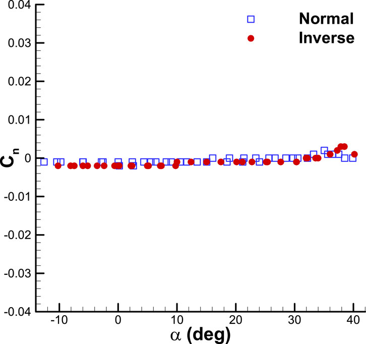
FIGURE 6. Variation of yawing moment coefficient with angle of attack for the aircraft model without the ground plane.
Figures 7, 8 present static ground effect data. These figures compare the variations of lift and drag coefficient with ground heights for the 60° delta wing-body-tail (Figure 2) with the 60° delta wing and the F-106 model (Lee et al., 1987b) at an angle of attack of 14° (Figure 7A; Figure 8A). In Figures 7, 8 the data related to H/b larger than 1.6 are related to out-of-ground. As shown in these figures for lift coefficient for wing-body-tail configuration the lift coefficient decreases relative to wing alone configuration due to body (fuselage) presence because at wing-body-tail configuration the real wing area is less than the wing reference area because of the presence of the body. But for the F106 model, the fuselage is a lifting body so the lift coefficient is near to the wing-alone configuration ones. In other words, the lift of the fuselage compensated for the lift decreasing due to decreasing the real wing area. In Figure 7B, Figure 8B, the data are plotted as a percentage increase in lift and drag coefficient. The findings consistently demonstrate that lowering the ground height results in higher lift coefficients, lower drag coefficients, and improved longitudinal stability (as evidenced by the more negative slope of the pitching moment curve in relation to the lift coefficient). When the aircraft is not in contact with the ground, as the angle of attack increases, the delta wing leading-edge vortices tend to move towards the middle section of the wing. This reduces wing loading near the wing tips, resulting in a less negative pitching moment. However, when the ground plane is present, the power of the leading-edge vortices increases and they move towards the external part of the wing. Consequently, the pitching moment becomes more negative in the ground effect.
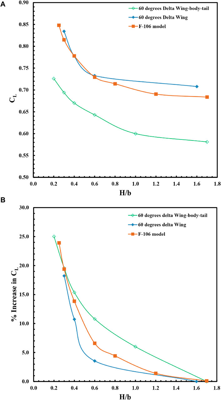
FIGURE 7. Variation of (A) lift coefficient and (B) lift increment with ground heights for the delta wing, delta wing-body-tail and F-106 model at the angle of attack of 14°.
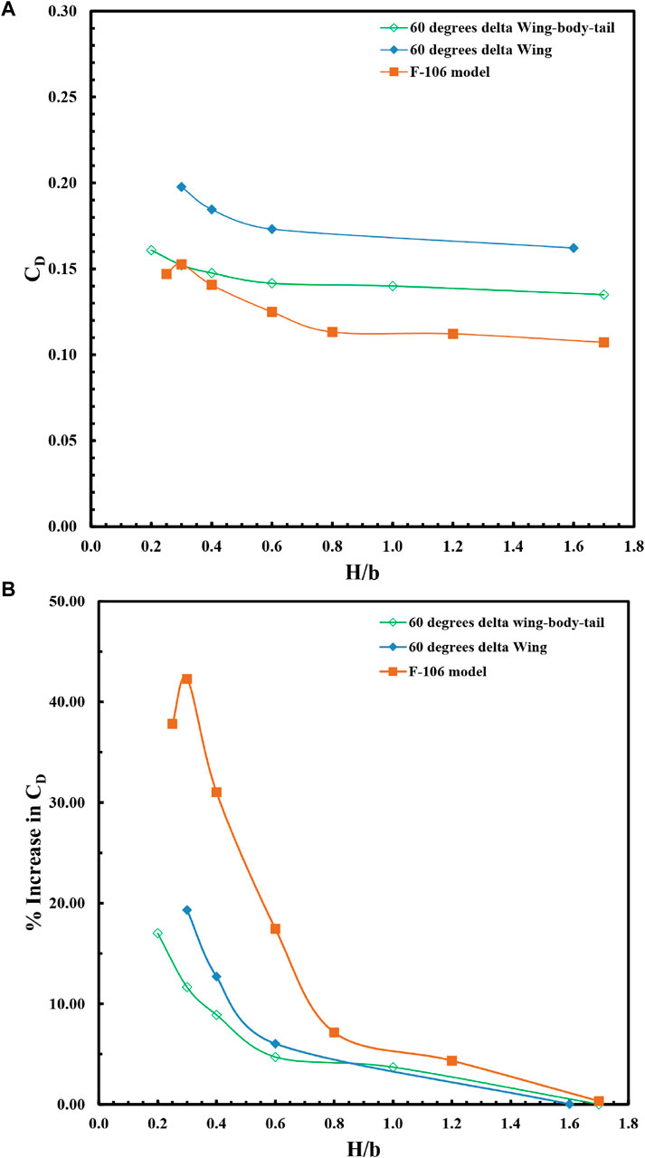
FIGURE 8. Variation of (A) drag coefficient and (B) drag increment with ground heights for the delta wing, delta wing-body-tail and F-106 model at the angle of attack of 14°.
Figures 9, 10 depict the changes in lift coefficient concerning the angle of attack for the delta wing-body-tail combination under ground effect in comparison to out-of-ground effect conditions. The graph includes data from the 60° delta wing model and the F-106 model (Lee et al., 1987b). At low angles of attack, a linear relationship exists between the coefficients of lift and pitching moment and the angle of attack (Figures 11, 12). However, at higher angles of attack, the lift coefficient and moment curves become nonlinear due to the influence of leading-edge vortices. In the case of a delta wing-body-tail combination, as the height from the ground decreases at each angle of attack, the lift coefficient value and the slope of the lift curve increase. The presence of the ground increases the maximum lift coefficient from 1.3 to 1.38. Overall, the results indicate that reducing the ground height leads to increased lift coefficients and lift curve slope (Figures 9, 10), decreased drag coefficients (Figures 13, 14), and increased longitudinal stability (Figures 11, 12).
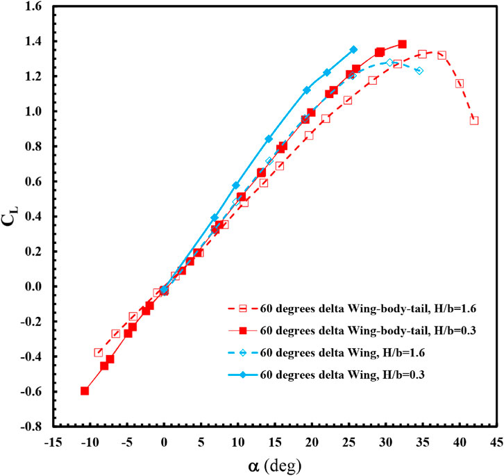
FIGURE 9. Variation of lift coefficient with angle of attack for the delta wing, delta wing-body-tail model in ground effect (H/b = 0.3) and out of ground effect (H/b = 1.6).
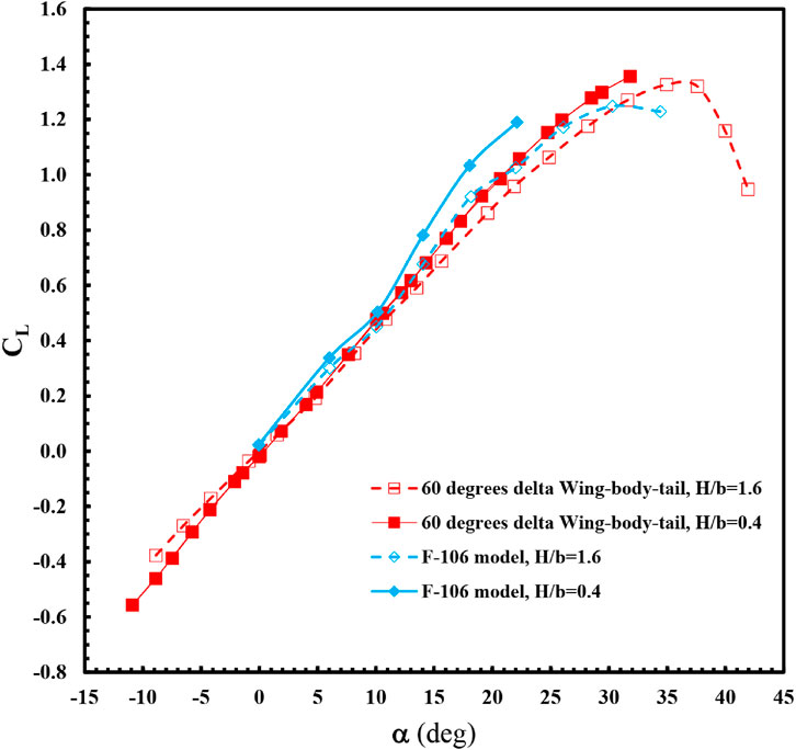
FIGURE 10. Variation of lift coefficient with angle of attack for the delta wing-body-tail, F-106 model in ground effect (H/b = 0.4) and out of ground effect (H/b = 1.6).
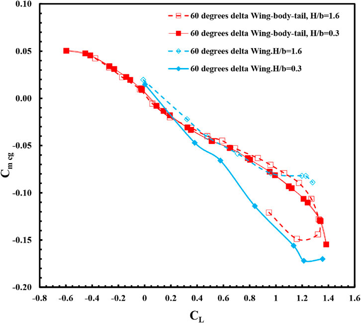
FIGURE 11. Variation of pitching moment coefficient with angle of attack for the delta wing, delta wing-body-tail model in ground effect (H/b = 0.3) and out of ground effect (H/b = 1.6).
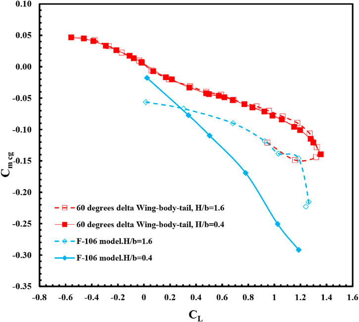
FIGURE 12. Variation of pitching moment coefficient with lift coefficient for the delta wing-body-tail, F-106 model in ground effect (H/b = 0.4) and out of ground effect (H/b = 1.6).
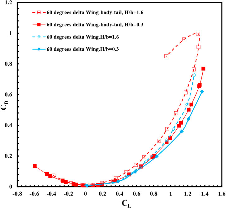
FIGURE 13. Variation of drag coefficient with angle of attack for the delta wing, delta wing-body-tail model in ground effect (H/b = 0.3) and out of ground effect (H/b = 1.6).
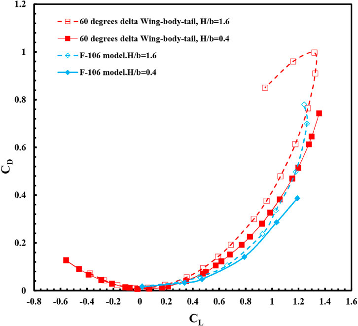
FIGURE 14. Variation of drag coefficient with lift coefficient for the delta wing-body-tail, F-106 model in ground effect (H/b = 0.4) and out of ground effect (H/b = 1.6).
4 Conclusion
Gaining a comprehensive understanding of the aerodynamic characteristics of a delta wing aircraft in ground effect is vital for optimizing its performance and ensuring safe flight conditions. The purpose of this investigation was to examine the influence of ground effects on the aerodynamic coefficients of a model delta wing aircraft. Through conducting experiments, valuable insights were gained into the aerodynamic behavior of an aircraft model equipped with a 60° delta wing-body-vertical tail, under various ground effect conditions. The results of the experimental tests, which were carried out in a subsonic wind tunnel, unveiled a number of important findings. One key finding was that increasing the proximity to the ground led to improved longitudinal static stability. When the model’s height from the ground plane was less than half of the wing span, the lift curve slope increased by 16.9%. Additionally, the study demonstrated that ground effect resulted in elevated lift coefficients at all angles of attack. Specifically, at an angle of attack of 14°, the lift increased by approximately 25% due to ground effects. When the delta wing model was in close proximity to the ground, there was a 6% increase in the maximum lift coefficient. These variations were particularly significant when the distance from the ground plane was less than half of the wing span.
Moreover, the research emphasized the importance of considering the design of the vertical tail in delta wing aircraft operating under ground effect conditions. The vertical tail plays a crucial role in maintaining stability and control, especially in the presence of altered flow patterns caused by ground effects. This study shed light on the optimal design parameters for the vertical tail, thereby contributing to the overall performance and safety of the aircraft. It further emphasized the significance of incorporating ground effects into the design and optimization of delta wing aircraft, as it has the potential to significantly enhance lift generation capabilities. The presence of a ground plane has the added benefit of strengthening the flow of leading-edge vortex towards the outboard section of the wing. This, in turn, results in a more negative pitching moment, causing a steeper decline in the pitching moment curve. As a result, there is an increase in static longitudinal stability and a shift backward in the aerodynamic center. Additionally, reducing the distance between the ground plane and the wing leads to a decrease in the total drag coefficient for all angles of attack. This decrease is primarily due to a reduction in the induced drag coefficient. Consequently, there is a significant improvement in the aerodynamic efficiency parameter (L/D) when the distance from the ground plane is decreased. These findings have important implications for the control and stability of delta wing aircraft, especially at high angles of attack. However, it is crucial to note that the study identified a stability issue with the rolling moment and yawing moment coefficients becoming unstable at angles of attack above 30°. This highlights the necessity for further research and analysis to address this instability and ensure the safe operation of delta wing aircraft in high-angle-of-attack scenarios. Further research in this field is encouraged to explore additional variables and circumstances that may affect the aerodynamic coefficients under ground effects. This will enhance the comprehensive understanding of delta wing aircraft behavior and aid in the development of improved design strategies for heightened performance and safety in low-altitude flight operations.
Data availability statement
The original contributions presented in the study are included in the article/Supplementary material, further inquiries can be directed to the corresponding author.
Author contributions
AS: Writing–original draft, Writing–review and editing. AG: Writing–original draft, Writing–review and editing.
Funding
The author(s) declare that no financial support was received for the research, authorship, and/or publication of this article.
Conflict of interest
The authors declare that the research was conducted in the absence of any commercial or financial relationships that could be construed as a potential conflict of interest.
Publisher’s note
All claims expressed in this article are solely those of the authors and do not necessarily represent those of their affiliated organizations, or those of the publisher, the editors and the reviewers. Any product that may be evaluated in this article, or claim that may be made by its manufacturer, is not guaranteed or endorsed by the publisher.
References
Abdolahipour, S. (2023). Effects of low and high frequency actuation on aerodynamic performance of a supercritical airfoil. Front. Mech. Eng. 9. doi:10.3389/fmech.2023.1290074
Abdolahipour, S., Mani, M., and Shams Taleghani, A. (2022a). Pressure improvement on a supercritical high-lift wing using simple and modulated pulse jet vortex generator. Flow, Turbul. Combust. 109 (1), 65–100. doi:10.1007/s10494-022-00327-9
Abdolahipour, S., Mani, M., and Shams Taleghani, A. (2022b). Experimental investigation of flow control on a high-lift wing using modulated pulse jet vortex generator. J. Aerosp. Eng. 35 (5), 05022001. doi:10.1061/(asce)as.1943-5525.0001463
Abdolahipour, S., Mani, M., and Taleghani, A. S. (2021). Parametric study of a frequency-modulated pulse jet by measurements of flow characteristics. Phys. Scr. 96 (12), 125012. doi:10.1088/1402-4896/ac2bdf
Adam, R., and Bartoszewicz, J. (2017). Numerical analysis of the influence of the wing in ground effect on aircraft lift coefficient and car downforce coefficient. J. Mech. Transp. Eng. 69 (2), 47–55. doi:10.21008/j.2449-920X.2017.69.2.06
Ahmed, M. R., and Sharma, S. D. (2005). An investigation on the aerodynamics of a symmetrical airfoil in ground effect. Exp. Therm. Fluid Sci. 29, 633–647. doi:10.1016/j.expthermflusci.2004.09.001
Ahmed, M. R., Takasaki, T., and Kohama, Y. (2007). Aerodynamics of a NACA 4412 airfoil in ground effect. AIAA J. 45 (1), 37–47. doi:10.2514/1.23872
Albers, M., Meysonnat, P. S., and Schröder, W. (2019). Actively reduced airfoil drag by transversal surface waves. Flow, Turbul. Combust. 102, 865–886. doi:10.1007/s10494-018-9998-z
Atzori, M., Vinuesa, R., Fahland, G., Stroh, A., Gatti, D., Frohnapfel, B., et al. (2020). Aerodynamic effects of uniform blowing and suction on a NACA4412 airfoil. Flow, Turbul. Combust. 105, 735–759. doi:10.1007/s10494-020-00135-z
Baker, P. A., Schweikhard, W. G., and Young, W. R. (1970). Flight evaluation of ground effect on several low aspect ratio airplanes. NASA TN D 6053.
Chang, R. C., and Muirhead, V. U. (1985). “Investigation of dynamic ground effect,” in Proceedings of the 1985 NASA Ames Research Center's Ground-Effects Workshop, NASA CP-2462, Aug. 20, 1985, 363–393.
Chang, R. C., and Muirhead, V. U. (1987). Effect of sink rate on ground effect of low-aspect-ratio wings. J. Aircr. 24, 176–180. doi:10.2514/3.45413
Chawla, M., Edwards, L., and Franke, M. (1990). Wind-tunnel investigation of wing-in-ground effects. J. Aircr. 27 (4), 289–293. doi:10.2514/3.25270
Corsiglia, V. R., Koenig, D. G., and Morelli, J. P. (1969). Large scale test of an airplane model with a double delta wing including longitudinal and lateral aerodynamic characteristics and ground effects. NASA TN D 5102.
Deng, N. (2017). Numerical study of the aerodynamics of DLR-F6 wing-body in unbounded flow field and in ground effect. Master of Engineering thesis. Louis: Washington University.
Deng, N., Qu, Q., and Agarwal, R. K. (2017). “Numerical study of the aerodynamics of DLR-F6 wing-body in the unbounded flow field and in ground effect,” in 55th AIAA Aerospace Sciences Meeting, Grapevine, Texas, 9 - 13 January 2017.
Djavareshkian, M. H., Esmaeli, A., and Parsani, A. (2011). Aerodynamics of smart flap under ground effect. J. Aerosp. Sci. Technol. 15 (8), 642–652. doi:10.1016/j.ast.2011.01.005
Fahland, G., Atzori, M., Frede, A., Stroh, A., Frohnapfel, B., and Gatti, D. (2023). Drag assessment for boundary layer control schemes with mass injection. Flow, Turbul. Combust. 2023. doi:10.1007/s10494-023-00462-x
Gratzer, L. B., and Mahal, A. S. (1971). Ground effects in STOL operation. J. Aircr. 19 (3), 236–242. doi:10.2514/3.58963
Harvey, J., and Perry, F. J. (1971). Flow field produced by trailing vortices in the vicinity of the ground. AIAA J. 9 (8), 1659–1660. doi:10.2514/3.6415
He, W., Peng, Y., Larry, K., and Li, B. (2018). Ground effects on the stability of separated flow around a NACA 4415 airfoil at low Reynolds numbers. J. Aerosp. Sci. Technol. 72, 63–76. doi:10.1016/j.ast.2017.10.039
Katz, J., and Levin, D. (1984). Measurements of ground effect for delta wings. J. Aircr. 21 (6), 441–443. doi:10.2514/3.44988
Kemmerly, G. T., Paulson, J. W., and Compton, M. (1988). Exploratory evaluation of moving-model technique for measurement of dynamic ground effects. J. Aircr. 25 (6), 557–562. doi:10.2514/3.45622
Kemp, W. B., Lockwood, V. E., and Phillips, W. P. (1966). Ground effects related to landing of airplanes with low aspect ratio wings. NASA TN D 3583.
Kornilov, V. (2021). Combined blowing/suction flow control on low-speed airfoils. Flow, Turbul. Combust. 106, 81–108. doi:10.1007/s10494-020-00157-7
Lee, P. H., Edward Lan, C., and Muirhead, V. U. (1987b). An experimental investigation of dynamic ground effect. NASA CR-4105.
Lee, P. H., Lan, C. E., and Muirhead, V. U. (1987a). An experimental investigation of dynamic ground effect. NASA CR-4105.
Lee, P. H., Lan, C. E., and Muirhead, V. U. (1989). Experimental investigation of dynamic ground effect. J. Aircr. 26 (6), 497–498. doi:10.2514/3.45793
Lee, T. W. (2002). Experimental study of ground effect on finite-wing wake flow development. M.S. Thesis, Aeronautics and Astronautics Dept. Tainan City, Taiwan: National Cheng Kung University. (in Chinese).
Lockwood, V. E., and Phillips, W. P. (1968). Measurements of ground effect on a low aspect ratio ogee wing airplane model and calculations of landing flare trajectories. NASA TN D 4329.
McDonnell Douglas Corporation, USAF Stability and Control DATCOM (1960). U.S. Air force flight dynamics laboratory. Ohio: Wright-Patterson AFB. Revised Apr. 1976.
Mirzaei, M., Taleghani, A. S., and Shadaram, A. (2012). Experimental study of vortex shedding control using plasma actuator. Appl. Mech. Mater. 186, 75–86. doi:10.4028/www.scientific.net/amm.186.75
Mohammadi, M., and Taleghani, A. S. (2014). Active flow control by dielectric barrier discharge to increase stall angle of a NACA0012 airfoil. Arabian J. Sci. Eng. 39, 2363–2370. doi:10.1007/s13369-013-0772-1
Nirooei, M. H. (2018). Aerodynamic and static stability characteristics of airfoils in extreme ground effect. J. Aerosp. Eng. 232 (6), 1134–1148. doi:10.1177/0954410017708212
Paulson, J. W., Kemmerly, G. T., and Gilbert, W. P. (1990). Dynamic ground effects, aerodynamics of combat aircraft controls and ground effects, 1–12. AGARD CP-465.
Qin, Y., Liu, P., Qu, Q., and Guo, H. (2016). Numerical study of aerodynamic forces and flow physics of a delta wing in dynamic ground effect. J. Aerosp. Sci. Technol. 51, 203–221. doi:10.1016/j.ast.2016.02.007
Qin, Y., Liu, P., Qu, Q., and Hu, T. X. (2017). Wing/canard interference of a close-coupled canard configuration in static ground effect. J. Aerosp. Sci. Technol. 69, 60–75. doi:10.1016/j.ast.2017.06.012
Qin, Y., Qu, Q., Liu, P., Tian, Y., and Lu, Z. (2015). DDES study of the aerodynamic forces and flow physics of a delta wing in static ground effect. J. Aerosp. Sci. Technol. 43, 423–436. doi:10.1016/j.ast.2015.04.004
Qu, Q., Jia, X., Wang, W., Liu, P., and Agarwal, R. K. (2014). Numerical study of the aerodynamics of a NACA 4412 airfoil in dynamic ground effect. J. Aerosp. Sci. Technol. 38 (6), 56–63. doi:10.1016/j.ast.2014.07.016
Rodriguez, I., Lehmkuhl, O., and Borrell, R. (2020). Effects of the actuation on the boundary layer of an airfoil at Reynolds number Re= 60000. Flow, Turbul. Combust. 105, 607–626. doi:10.1007/s10494-020-00160-y
Rolls, L. S., and Koenig, D. G. (1966). Flight measured ground effect on a low aspect ratio ogee wing including a comparison with wind tunnel results. NASA TN D 3431.
Salmasi, A., Shadaram, A., and Taleghani, A. S. (2013). Effect of plasma actuator placement on the airfoil efficiency at poststall angles of attack. IEEE Trans. Plasma Sci. 41 (10), 3079–3085. doi:10.1109/tps.2013.2280612
Sereez, M., Abramov, N. B., and Goman, M. G. (2017). “Computational ground effect aerodynamics and airplane stability analysis during take-off and landing,” in 7th European Conference For Aeronautics And Aerospace Sciences (EUCASS), Milan, Italy Duration, 3 Jul 2017, 6 Jul 2017. doi:10.13009/EUCASS2017-376
Sereez, M., Abramov, N. B., and Goman, M. G. (2018). Impact of ground effect on airplane lateral directional stability during take-off and landing. Open J. Fluid Dyn. 08, 1–14. doi:10.4236/ojfd.2018.81001
Snyder, C. T., Drinkwater, F. J., and Jones, A. D. (1970). A piloted simulator investigation of ground effect on the landing maneuver of a large tailless delta wing airplane. NASATND6046.
Taleghani, A. S., Ghajar, A., and Masdari, Me. (2020). Experimental study of ground effect on horizontal tail effectiveness of a conceptual advanced jet trainer. J. Aerosp. Eng. 33. doi:10.1061/(ASCE)AS.1943-5525.0001140
Taleghani, A. S., Shadaram, A., and Mirzaei, M. (2012). Effects of duty cycles of the plasma actuators on improvement of pressure distribution above a NLF0414 airfoil. IEEE Trans. Plasma Sci. 40 (5), 1434–1440. doi:10.1109/tps.2012.2187683
Tavakoli Dakhrabadi, M., and Seif, M. S. (2016). Influence of main and outer wings on aerodynamic characteristics of compound wing-in-ground effect. J. Aerosp. Sci. Technol. 55, 177–188. doi:10.1016/j.ast.2016.06.002
Wang, Q. X. (2005). Analyses of a slender body moving near a curved ground. Phys. Fluids 17 (9), 097102. doi:10.1063/1.2034867
Wentz, W. H. (1968). “Wind-Tunnel investigations of vortex breakdown on slender sharp-edge wing”. Ph.D. dissertation. Kansas: University of Kansas.
Zerihan, J., and Zhang, X. (2000). Aerodynamics of a single element wing in ground effect. J. Aircr. 37 (6), 1058–1064. doi:10.2514/2.2711
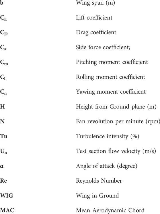
Nomenclature
Keywords: aircraft, wind tunnel, ground simulator, aerodynamic efficiency, delta wing, ground effects, vertical tail
Citation: Shams Taleghani A and Ghajar A (2024) Aerodynamic characteristics of a delta wing aircraft under ground effect. Front. Mech. Eng 10:1355711. doi: 10.3389/fmech.2024.1355711
Received: 14 December 2023; Accepted: 29 February 2024;
Published: 13 March 2024.
Edited by:
Jian Wu, Harbin Institute of Technology, ChinaReviewed by:
Cetin Canpolat, Çukurova University, TürkiyeYu Zhang, Harbin Institute of Technology, China
Copyright © 2024 Shams Taleghani and Ghajar. This is an open-access article distributed under the terms of the Creative Commons Attribution License (CC BY). The use, distribution or reproduction in other forums is permitted, provided the original author(s) and the copyright owner(s) are credited and that the original publication in this journal is cited, in accordance with accepted academic practice. No use, distribution or reproduction is permitted which does not comply with these terms.
*Correspondence: Arash Shams Taleghani, Arash.taleghani@gmail.com