Design and research of an automatic grasping system for a robot arm based on visual image capture technology
 Xiaofan Liu
 Shaomeng Ren1
 - 1Department of Mechanical Engineering, Hebei Institute of Mechanical and Electrical Technology, Xingtai, China
- 2Department of Electrical Engineering, Hebei Institute of Mechanical and Electrical Technology, Xingtai, China
Traditional robotic arms rely on complex programming and predefined trajectories to operate, which limits their applicability. To improve the flexibility and adaptability of the robot arm, the research focuses on improving the grasping performance of the robot arm based on vision technology. Kinect technology is used to capture human arm movements, and Kalman filter is introduced to smooth image data, so as to optimize the motion recognition process. In this study, the residual network model is further improved, and ELU activation function and pre-activation mechanism are introduced to enhance the classification accuracy of gesture images. The results showed that the improved ResNet50 model achieves 95% recognition accuracy after 25 iterations of training, while the original model is 80%. The application of Kalman filter makes the motion tracking curve smoother and shows the correction effect of this method. In simulation tests, the robotic arm is able to identify different elbow bending angles with 90–96 percent accuracy, while mimicking five specific hand gestures with 96–98 percent accuracy. These data support the practicability and effectiveness of the application of vision capture technology and deep learning model in the field of intelligent control of robotic arms.
1 Introduction
Kinect device is a human-computer interaction device developed by Microsoft based on deep camera technology. It can obtain real-time user actions and environmental information through the combination of sensors and cameras (Alves et al., 2020). The Kinect device combines a depth camera, an RGB camera, and multiple sensors to capture human movements, facial expressions, and voice commands. In recent years, Kinect technology has been widely used in the field of robotics, which analyzes these data to achieve real-time human-computer interaction. In the field of robotics, especially in the control and operation of robotic arms, Kinect technology is used to improve grasp accuracy and efficiency. It can capture the position, shape and attitude of the target object in real time, and assist the robot arm to grasp it more accurately (Li R. et al., 2021). Traditional robotic arm grasping techniques typically require tedious programming and calibration, and often have poor performance in grasping complex shapes and uncertain targets (Malik et al., 2020). The Kinect technology provides real-time motion capture, which is essential for the control of robotic arms that require rapid response. Kinect integrates depth information, visual information, and motion capture, which provides more comprehensive data support for complex grasping tasks. Kinect technology has good adaptability to objects of different shapes and sizes, which makes it have wide application potential in the field of robot grasping. However, Kinect technology still has limitations in the grasp control of robotic arm. The spatial resolution and depth accuracy of Kinect sensor are limited, which may affect the recognition and processing of subtle movements or small target objects. When the object is partially obscured by other objects, Kinect may have difficulty accurately capturing the full shape and position of the target. Therefore, to explore the technical characteristics of Kinect devices in the field of robotic arm control and improve the accuracy of robotic arm grasping control, this study is based on Kinect technology to extract human arm posture images, and constructs gesture action image recognition and robotic arm grasping models based on an improved residual network (ResNet) model (Jaroonsorn et al., 2020). The innovation of the research is that Kinect technology is innovatively applied to the control of the robot arm, and the depth camera is used to capture the posture of the human arm, to achieve accurate control of the robot arm. In the processing of Kinect captured images, Kalman filter (KF) is used for the first time to smooth and optimize the image data. By introducing ELU activation function and pre-activation operation, the ResNet is improved, and a mapping relationship model between human arm and robotic arm is constructed to achieve high-precision imitation under different joint angles and gesture states.
This study is composed of four parts. The first part explores the research outcomes of domestic and foreign scholars on visual image capture technology and robotic arm control technology. The second part preprocesses the human arm posture images extracted by Kinect technology using the KF method. An improved ResNet is used to classify the action images of mechanical claws. By constructing a mapping relationship model between the human arm and the robotic arm, the goal is to control the motion of the robotic arm using the angle transformation of the human arm. The third part conducts performance testing and analysis on the constructed model. The fourth part summarizes the article and proposes shortcomings.
2 Related works
Kinect technology can extract information such as the position, shape, and posture of targets from images, and plays an important role in the field of machinery. Some experts and scholars have conducted relevant research based on this. Li et al. constructed a real-time tracking control method for robots. This method integrated the position and joint angle information of robot actuators, achieving real-time estimation of user motion. By combining Kinect sensors with the robot operating system, the motion coordinates of each joint of the robot were worked out to achieve human-machine coordinate conversion. Simulation experiments have demonstrated that this method had good robustness and accuracy (Li S. et al., 2021). Ting et al. proposed a safety strategy based on risk assessment and deceleration procedures to avoid collisions between robots and humans. Kinect sensors were utilized to estimate the distance between humans and robots, to slow down the robot’s speed. It further modified the robot’s motion by calculating virtual forces in the risk space. Through experiments, it has been verified that this method can meet the requirements for robots in human-machine cooperation (Ting et al., 2020). Anuradha et al. believed that human following robots can be achieved using various methods, such as stereo cameras, laser rangefinders, and RFID systems. Therefore, based on Kinect sensors, human bone views were recognized and tracked. The experimental results showed that this technology could accurately detect the position and distance of people (Anuradha et al., 2020). Wang et al. estimated the motion of each fingertip based on a combination of RGB images and depth image data obtained from Kinect sensors, to achieve gesture recognition. Specific algorithms were used in the proposed system to calibrate using the camera’s focal length and angle range. The experimental results demonstrated the robustness and real-time performance of the system (Wang et al., 2020).
As an indispensable part of the robot structure, the robotic arm plays an important role in the industrial field, and many experts and scholars have conducted relevant research on it. Zou Y et al. constructed a weld tracking method based on near-end strategy optimization, taking the reference image block and the image block to be detected as the double-channel input of the network, predicting the translation relationship between the two images, and correcting the position of the feature points in the weld image. Offline simulation results show that the proposed algorithm has strong robustness and performs well on the noisy surface joint image test set (Zou and Zhou, 2022). Mikkelstrup AF et al. performed A 3D scan of the weld to locally determine the gradient and curvature of the weld surface to locate the weld toe. Based on the weld toe position, an adaptive robot processing trajectory is generated that precisely tracks the curvature of the weld toe and adjusts the tool orientation according to the weld profile. Experiments comparing adaptive robotic therapy with manual and linear robotic therapy show that the developed system reduces the overall processing variance by 26.6% and 31.9%, respectively (Mikkelstrup et al., 2022). Dongming et al. proposed an analytical method that derived kinematic and dynamic equations. An impedance control algorithm has been developed to coordinate and control multiple robotic arms to capture targets. At the same time, gas jet thrusters were used to overcome the reaction of the robotic arm and maintain the position and attitude of the base stably. The experimental results validated the effectiveness of this method (Dongming et al., 2020). Nasir et al. proposed a new hybrid strategy by combining spiral dynamic algorithm and bacterial foraging algorithm. To solve engineering problems, the proposed algorithm was used to get and improve fuzzy logic control parameters for wheel angle tracking in a flexible robotic arm system. Performance testing analysis showed that the algorithm had significant improvement in performance, surpassing previous generation algorithms (Huang and Huang, 2021; Nasir et al., 2022).
In summary, the existing Kinect technology is mainly applied in the field of robot motion tracking, and only little research focuses on the control of robotic arm movements. Therefore, the robot arm automatic grasping model based on Kinect technology constructed in this study has important reference value in the field of mechanical control.
3 Construction of a robotic arm automatic grasping model based on visual image capture technology
To ensure the fit between the human arm and the robotic arm and achieve automatic grasping of the robotic arm, this chapter is broken into three parts for research. The first part preprocesses the human arm posture images extracted by Kinect technology using the KF method. The second part uses an improved ResNet to classify the action images of the mechanical claw, making it easier to control the grasping action of the mechanical claw. The third part constructs a mapping relationship model between the human arm and the robotic arm to realize the goal of using human arm angle transformation to control the motion of the robotic arm.
3.1 Human arm posture acquisition based on Kinect technology
Kinect technology is an advanced user interface technology developed by Microsoft, originally designed for the Xbox 360 gaming platform, and has since been widely used in robotics, healthcare, education, and other fields. The core function of Kinect is the ability to capture and recognize human movements, facial expressions, and voice commands, enabling interaction without physical contact. Kinect technology has several modules, such as depth sensing, color camera, microphone array, bone tracking and gesture recognition. Among them, depth sensing is that Kinect uses infrared transmitters and depth cameras to capture the depth information of the object. It builds a three-dimensional image of the environment by emitting invisible infrared points of light and using an infrared camera to capture the reflection of these points on the surface of an object. A color camera is a standard RGB color camera designed to capture high-resolution color images. This provides more contextual information in image recognition and processing. The microphone array is a set of microphones included in the Kinect device that captures sound signals and supports sound source location and noise suppression. This allows it to process voice commands and perform environmental sound analysis. Kinect is able to recognize and track the bone and joint positions of multiple users, which allows it to analyze human movement and posture. This is important for applications such as motion capture, game controls, and physical therapy. By analyzing depth images and bone positions, Kinect is able to recognize specific gestures and movements, such as waving, jumping, and more. This is useful in interactive games and user interface design. In the research, modules such as depth camera, infrared irradiation and sound sensor are used to realize the perception and recognition of users’ movements, gestures and voices. Kinect hardware structure and data extraction process are shown in Figure 1.
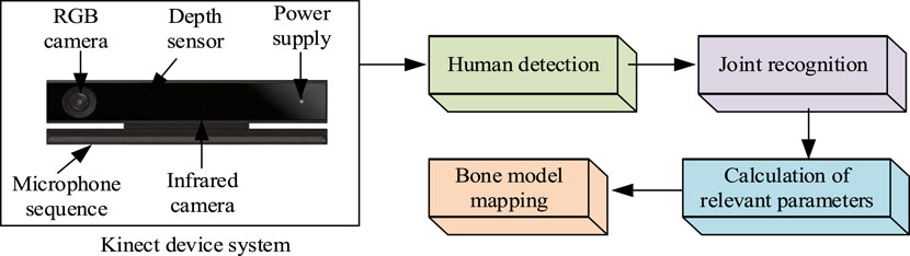
Figure 1. Kinect device hardware structure and data extraction process.
Due to the different shapes of the human body, it can affect the accuracy of the figure contour images obtained by Kinect technology. When processing images, the information constructed by human edges is prone to occlusion or overlap (Thomas et al., 2022). At this point, there may be errors in the coordinates of the human arm joint points, resulting in poor tracking performance of the joint points. KF is often applied to the collection and position estimation of target points, and can also make the coordinates more continuous in the time series. Therefore, this method is used to smooth the coordinates of human joint points (Kuo and Tang, 2022). KF is mainly divided into prediction and correction stages, in which the position of the next second’s coordinate needs to be predicted by comparing the coordinate position of the joint point in the previous second (Zhou et al., 2020). In the correction stage, it is necessary to compare the actual position coordinates with the estimated position coordinates and calculate the difference. Repeated updates and iterations are needed to achieve the minimum error between the predicted and actual values. Because human arm movements can be approximated as a linear system (Abdul-Adheem et al., 2021), the established joint system equation is shown in Equation 1.
In Equation 1,
In Equation 2,
In Equation 3,
In Equation 4,
In Equation 5,
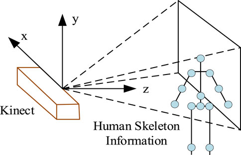
Figure 2. Schematic diagram of 3D coordinates extracted by Kinect device.
In Figure 2, the horizontal direction facing the human body is the z-axis, the vertical direction with the camera is the y-axis, and the horizontal left and right positions of the camera are the x-axis. It sets the joint point coordinates obtained by the Kinect device to
In Equation 6,
In Equation 7,
In Equation 8,
In Equation 9, the vector from the right shoulder to the elbow joint is
3.2 Construction of a gesture image recognition model based on improved ResNet
During the grasping action of the robotic arm, in addition to controlling the robotic arm, it is also necessary to collect gesture images and classify them to determine the current gesture status of the robotic claw (Li and Huang, 2020; Yonemoto and Suwa, 2020). ResNet is often used in the field of image classification due to its residual structure, which can effectively reduce the problem of gradient vanishing or exploding. Due to the fact that the grasping action mainly includes five states: grasping small objects, grasping large objects, stopping operation, closing, and no gesture, without the need for overly complex neural network structures, ResNet50 is chosen as the basic model, and its model architecture is shown in Figure 3.
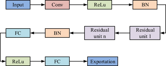
Figure 3. ResNet50 architecture diagram.
The ReLU activation function is used between convolutional layers in traditional residual structures, but this function cannot meet certain requirements when dealing with large datasets (Al-Dujaili et al., 2020). The ELU activation function still has output information when the input value is negative, as shown in Equation 10.
The ELU activation function and derivative diagram are shown in Figure 4.
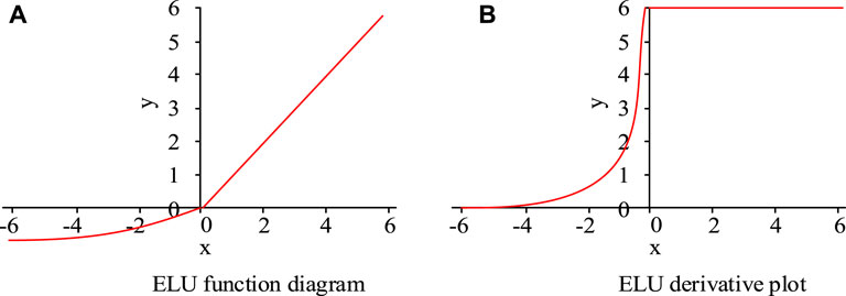
Figure 4. ELU activation function and derivative diagram. (A) ELU function diagram (B) ELU derivation plot.
From Figure 4, when the input value of the ELU function is greater than 0, there is a linear relationship between the output and input values, with a constant derivative of one and the parameters remaining updated (Xin et al., 2021). When the input value is less than 0, the output information always exists and tends to balance, which improves the robustness of the model compared to the traditional ReLU function. However, when the input data is directly input into the ELU function, it will also cause an increase in computational complexity. Therefore, the residual block will be widened so that some of the input neurons pass through the ReLU function and some pass through the ELU function. The expression proof is shown in Equation 11.
In Equation 11,
In Equation 12,
In Equation 13,
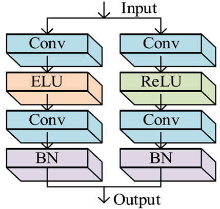
Figure 5. Structure diagram of residual blocks before and after improvement.
The dataset of gestures is relatively limited. To better train the model, BN and RelU layers are added before the convolutional layer of the ResNet to achieve the goal of model pre-activation (Kuo et al., 2020). Meanwhile, to visually express the results, the Softmax function is utilized for classification in the fully connected output layer, and the expression of the function is shown in Equation 14.
In Equation 14, the numerator represents that the input real value can obtain an output greater than 0 after
In Equation 15,
3.3 Mapping model of human arm and robotic arm
By improving the ResNet model, gesture recognition can be achieved to control the movement of the mechanical claw. For the control of a robotic arm, it is first necessary to describe the position and attitude of the robotic arm (Ashhepkova, 2020). The positional relationship between the links of the robotic arm can be determined through a reference Cartesian coordinate system
In Equation 16,
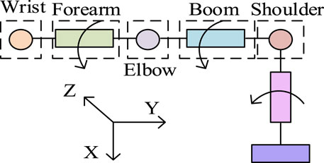
Figure 6. Mechanical arm structure model.
Due to the difference between the length of the human arm and the joint length of the robotic arm, and the redundant connection of the robotic arm, it can rotate 360° (Zan, 2022). The maximum rotation angle between the human arm and shoulder joint can reach 270°, so it is necessary to model the mapping relationship between the human arm and the robotic arm. It sets the coordinates of the wrist point to
By using Equation 17, the rotation angle of the elbow joint, which is the angle that the robotic arm needs to rotate, can be obtained, as shown in Equation 18.
According to Equation 18, the mapping value of the angle value can be obtained as
Similarly, the bending angle of the middle finger can be obtained through Equation 19 as shown in Equation 20.
According to Equation 20, the mapping value of the bending angle of the mechanical claw can be obtained as
4 Performance testing and analysis of gesture classification and grasping models
To assess the performance of the constructed model, this chapter is broken into two parts for model performance testing and analysis. The first part uses model testing related parameters to test and analyze the gesture image classification model based on an improved ResNet. The second part will conduct experiments on the robotic arm grasping model under simulation conditions to analyze its performance.
4.1 Testing and analysis of gesture image classification model based on improved ResNet
This experiment was conducted in an environment with Intel I9-9900K processor, Nvidia RTX2080TI 11 GB graphics card, 32 GB memory, Windows 10 64bit operating system, Tensorflow GPU 1.14.0, CUDA Toolkit 10.0.130, CUDNN7.6.4, programming language Python. The hardware used by the gesture simulation robot includes robot arm, sensor, actuator and power supply. The robot arm adopts universal Robots UR5. The sensor is divided into vision sensor, force contact sensor and gyroscope. The vision sensor uses Intel RealSense D435, the force contact sensor uses ATI Mini40, and the gyroscope uses MPU-6050. The actuator comprises a motor, a hydraulic cylinder and a pneumatic motor. The motor adopts NEMA 17 stepper motor, the hydraulic cylinder adopts Bosch Rexroth R4805, and the pneumatic motor adopts SMC CJP2B16-5-B. The power supply system includes a power adapter and battery, the power adapter is the MeanWell LRS-350, and the battery is the Panasonic NCR18650B. The simulation software was Hardware in loop, which simulated real-world conditions and allowed researchers to test how robotic arms and gesture recognition systems interact with physical elements in real time, which was critical to ensuring accuracy and reliability in real-world scenarios. The safety and reliability of the system can be tested without exposing the hardware to dangerous situations that may arise early in development. A total of 1,000 gesture data samples were collected, including 800 training sets and 200 testing sets. Gesture actions included grabbing small objects, grabbing large objects, stopping operations, closing, and no gesture states. The size of the dataset was 224 × 224; learning rate was set to 0.01; Epoch was set to 25; batch size was set to 80; optimizer was random gradient descent method. The reason for choosing 25 iterations of the model was to prevent overfitting of the model. When the model iterated on the training data too many times, it might begin to learn noise and details in the data, resulting in overfitting. Training deep learning models usually requires a lot of computational resources and time, and limiting the number of Epochs helps to complete the experiment within a reasonable time frame. To evidence the accuracy of the optimized ResNet50 model, the original model was compared with the improved model for accuracy testing. The results are shown in Figure 7.
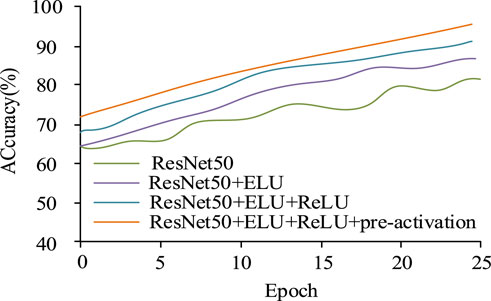
Figure 7. Accuracy iteration curve.
From Figure 7, after 25 iterations, the recognition accuracy value of the original ResNet50 model was 80%, while that of the ResNet50 model which only introduces the ELU activation function was 83%, and that of the ResNet50 model without pre-activation was 89%. The improved ResNet50 model in this study achieved a 95% accuracy. The results showed that the ELU activation function can help the network learn and generalize better than the activation function used in the original model. The ELU activation function improved the model performance through its characteristics. The application of activation functions and pre-activation operations before residual blocks could improve model performance, and pre-activation could reduce information loss and alleviate the problem of disappearing gradients, which is especially important in deep networks. To verify the effectiveness of dynamically adjusting the learning rate, the learning rates were set to 0.1 and 0.2, and the initial value of the dynamic learning rate was 0.1. The loss value change curve of the model is shown in Figure 8.
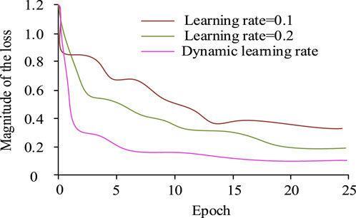
Figure 8. Curve of loss value change of the model.
From Figure 8, after 25 iterations, when the learning rate was set to 0.1 and 0.2, the loss value was 0.4 and 0.2, respectively. When it was set to dynamically adjust the learning rate, the loss value was 0.1. Therefore, dynamically adjusting the learning rate achieved lower loss values and had a greater impact on improving model performance. Dynamic adjustment of the learning rate was used, with the initial value still set to 0.1 and the remaining parameters unchanged. The P-R curves of the improved and the original ResNet50 models for recognizing five gestures are shown in Figure 9.
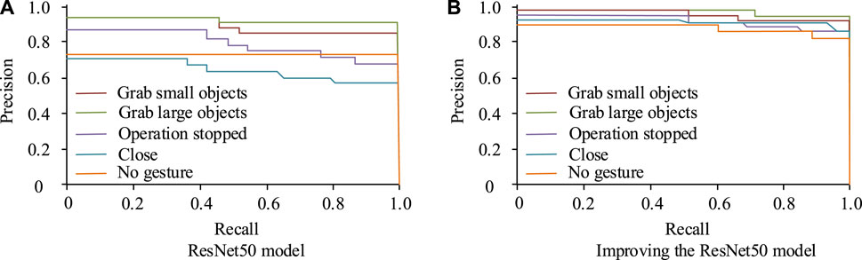
Figure 9. P-R curve for recognition of five gestures. (A) ResNet50 model (B) Improving the ResNet50 model.
In Figure 9, the horizontal axis represents recall rate and the vertical axis represents accuracy rate. The larger the area enclosed by the horizontal and vertical coordinates, the higher the recall and accuracy values obtained by the model, and the better the performance of the model. From the figure, the original ResNet50 model P-R curve obtained areas of 0.89, 0.92, 0.65, 0.78, and 0.75 for the five states of grasping small objects, grasping large objects, stopping operations, closing, and no gesture, respectively. The improved ResNet50 model P-R curve achieved an area of 0.92, 0.95, 0.90, 88, and 0.80 for the five states of grasping small objects, grasping large objects, stopping operations, closing, and no gesture, respectively. The improved ResNet50 model had a larger area enclosed by the P-R curve, thus achieving better performance. The comparison of ROC curves of the improved and the original ResNet50 models is shown in Figure 10.
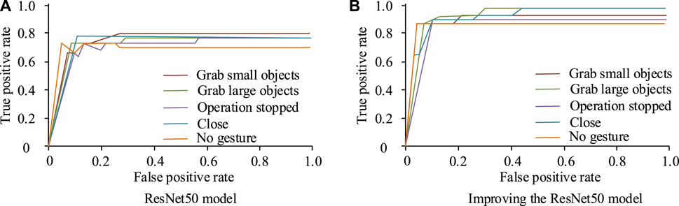
Figure 10. Comparison of ROC curves. (A) ResNet50 model (B) Improving the ResNet50 model.
In Figure 10, the horizontal and the vertical axes represent the false positive rate and the true rate, respectively. The ROC value is usually used to indicate the strength of the model’s generalization ability. When the ROC value was higher, it indicated that the model had stronger generalization ability. Figure 10 (a) shows the ROC curve of the original ResNet50 model. The areas obtained for grasping small objects, grasping large objects, stopping operations, closing, and no gesture states were 0.75, 0.70, 0.72, 0.73, and 0.68, respectively. Figure 10 (b) shows the ROC curve of the improved ResNet50 model. The areas obtained for grasping small objects, grasping large objects, stopping operations, closing, and no gesture states were 0.88, 0.90, 0.83, 0.88, and 0.85, respectively. Therefore, the improved ResNet50 model had stronger generalization ability for image recognition. To verify the advanced nature of the research method, the proposed method was compared with the methods in references (Dongming et al., 2020; Nasir et al., 2022) in the experiment, and the performance of the model was evaluated through the indexes of control accuracy and control completion time of the robot arm. The comparison results are shown in Table 1.
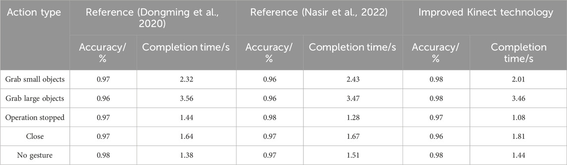
Table 1. Performance comparison of different methods.
In the results of Table 1, in terms of grasping small objects, the accuracy of the method in references (Dongming et al., 2020; Nasir et al., 2022) and the improved Kinect technology were 0.97, 0.96, and 0.98, the completion time was 2.32, 2.43, and 2.01 s, respectively. The results showed that the improved Kinect technology had a slight improvement in accuracy and a significant reduction in completion time, showing obvious advancement. In terms of capturing large objects, the accuracy of the methods in references (Dongming et al., 2020; Nasir et al., 2022) was 0.96, and the completion time was 3.56 s and 3.47 s, respectively. The improved Kinect technology has improved accuracy to 0.98, but the completion time was 3.46 s. In terms of operation stop, the accuracy of the method in reference (Dongming et al., 2020) was 0.97, and the completion time was 1.44 s. The accuracy of the method in reference (Nasir et al., 2022) was slightly higher, 0.98, and the completion time was 1.28 s. The accuracy rate of the improved Kinect technology was the same as that of the reference (Dongming et al., 2020), which was 0.97, but the completion time was 1.08 s. In terms of closure, the accuracy of the methods in references (Dongming et al., 2020; Nasir et al., 2022) was 0.97, and the completion time was 1.64 s and 1.67 s, respectively. The improved Kinect technology had a slightly lower accuracy rate of 0.96 and a completion time of 1.81 s. In the non-gesture aspect, the accuracy of the method in reference (Dongming et al., 2020) was 0.98, and the completion time was 1.38 s. The accuracy of the method in reference (Nasir et al., 2022) was 0.97, and the completion time was 1.51 s. The improved Kinect technology had an accuracy rate of 0.98 and a completion time of 1.44 s. The results showed that the improved Kinect technology was the same in accuracy as the reference (Dongming et al., 2020), but slightly worse in completion time. Compared with reference (Nasir et al., 2022), the accuracy was the same but the completion time was slightly better. In summary, the improved Kinect technology has a comparable performance with the current method, indicating that the method has a certain advancement.
4.2 Simulation testing and analysis of robotic arm grasping model
The experiment used a Baxter robot, with a robotic arm with 7 degrees of freedom, including eight links and seven joints, and a robotic claw with 2 degrees of freedom. The Kinect sensor adopted version 2.0, with an Intel I9-9900K processor, Nvidia RTX2080TI 11 GB graphics card, and 32 GB memory. It set the trajectory of the human right arm to up and down movements and left and right movements to meet the needs of daily grasping tasks. To verify the effectiveness of KF correction, the wrist motion trajectory of the robotic arm after KF correction was compared with the motion trajectory before correction, as shown in Figure 11.
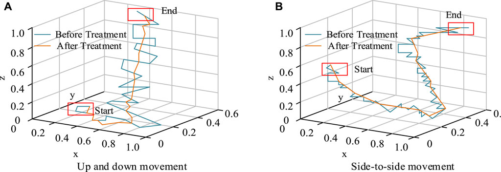
Figure 11. Motion trajectory before and after correction. (A) Up and down movement (B) Side-to-side movement.
In Figure 11, the blue curve represents the motion trajectory before filtering correction, and the orange curve represents the motion trajectory after filtering processing. At the beginning, there would be significant fluctuations due to a certain buffer time when the mechanical equipment was opened. As time went on, the shaking amplitude gradually decreased. Compared with Figure 11 (a) and (b), the motion curve after KF correction was smoother, proving the effectiveness of KF correction. To verify the accuracy of the recognition of the joint angle of the robotic arm skeleton, five different individuals were selected to collect 10 sets of data from different angles of elbow joint bending in the same environment, totaling 250 sets of data. The accuracy values of the recognition are shown in Table 2.
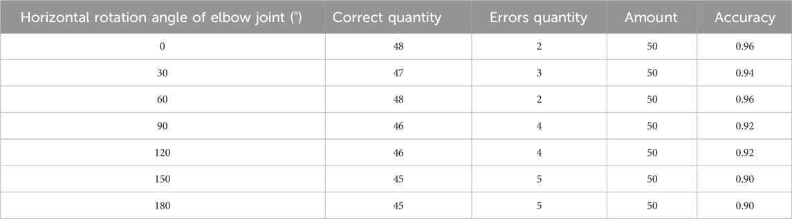
Table 2. Elbow joint recognition accuracy.
From Table 2, when the bending angles of the elbow joint were 0°, 30°, 60°, 90°, 120°, 150°, and 180°, the accuracy of identifying the joint angles of the robotic arm was 96.0%, 94.0%, 96.0%, 92.0%, 92.0%, 90.0%, and 90.0%, respectively. The robotic arm has achieved good results in angle recognition of the elbow joint. To test the accuracy of gesture imitation of the mechanical claw, five different people were selected to perform five gesture movements set for grasping in the same environment. Each action was performed 20 times, totaling 500 sets of data. The similarity of gesture imitation was determined, and the results are indicated in Table 3.
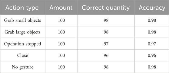
Table 3. Accuracy rate of gesture imitation.
From Table 3, the imitation accuracy rates for the five gesture states of grasping small objects, grasping large objects, stopping operation, closing, and no gesture were 98.0%, 98.0%, 97.0%, 96.0%, and 98.0%, respectively. Therefore, the robotic arm has also achieved good results in simulating the five grasping movements.
5 Conclusion
To solve the problem of precise control of robotic arm grasping gestures based on visual capture technology, this study preprocessed human arm posture images using the KF method. Based on an improved ResNet, the action images of mechanical claws were classified. Finally, a mapping relationship model was constructed between the human arm and the robotic arm. The performance test results of the improved ResNet model and the robotic arm showed that after 25 iterations, the recognition accuracy value of the original ResNet50 model was 80%. The recognition accuracy of the ResNet50 model that only introduces the ELU activation function was 83%, while that of the ResNet50 model without pre-activation was 89%. The ResNet50 model improved in this study achieved a 95% accuracy rate. The P-R curve of the improved ResNet50 model had an area of 0.92, 0.95, 0.90, 0.88, and 0.80 for the five states of grasping small objects, grasping large objects, stopping operation, closing, and no gesture, respectively. The ROC curve had an area of 0.88, 0.90, 0.83, 0.88, and 0.85 for the five states of grasping small objects, grasping large objects, stopping operation, closing, and no gesture, respectively. Compared with the original ResNet50 model, the improved ResNet50 model achieved better performance. The smoother motion curve after KF correction proved the effectiveness of KF correction. When the bending angles of the elbow joint were 0°, 30°, 60°, 90°, 120°, 150°, and 180°, the recognition accuracy of the joint angle of the robotic arm was 96.0%, 94.0%, 96.0%, 92.0%, 92.0%, 90.0%, and 90.0%, respectively. The imitation accuracy of the five gesture states was 98.0%, 98.0%, 97.0%, 96.0%, and 98.0%, respectively. Therefore, the robotic arm has also achieved good results in identifying joint angles and simulating the five grasping movements. The main contribution of this research is not only to improve the accuracy and efficiency of the grasp and operation of the robot arm, but also to demonstrate the practical application potential of visual image capture technology in the field of robotics, especially in improving the intelligence level of the robot arm. By integrating advanced image processing techniques and deep learning models, the research provides an effective solution for the automation and intelligence of robot grasping and manipulation tasks. However, there are still shortcomings in this study, which is mainly carried out in a simulation environment and does not involve complex or changeable practical application scenarios. Robotic arms and gesture recognition systems may behave differently in real environments than they do in laboratory conditions. Therefore, follow-up studies can be tested in real-world environments to assess the performance and reliability of the system in complex environments.
Data availability statement
The original contributions presented in the study are included in the article/Supplementary Material, further inquiries can be directed to the corresponding author.
Author contributions
XL: Conceptualization, Methodology, Writing–original draft. SR: Formal Analysis, Writing–original draft. GW: Methodology, Writing–original draft. LM: Software, Writing–review and editing. YS: Formal Analysis, Methodology, Writing–review and editing.
Funding
The author(s) declare that no financial support was received for the research, authorship, and/or publication of this article.
Conflict of interest
The authors declare that the research was conducted in the absence of any commercial or financial relationships that could be construed as a potential conflict of interest.
Publisher’s note
All claims expressed in this article are solely those of the authors and do not necessarily represent those of their affiliated organizations, or those of the publisher, the editors and the reviewers. Any product that may be evaluated in this article, or claim that may be made by its manufacturer, is not guaranteed or endorsed by the publisher.
References
Abdul-Adheem, W. R., Ibraheem, I. K., Humaidi, A. J., and Azar, A. T. (2021). Model-free active input–output feedback linearization of a single-link flexible joint manipulator: an improved active disturbance rejection control approach. Meas. Control 54 (5-6), 856–871. doi:10.1177/0020294020917171
Al-Dujaili, A. Q., Falah, A., Humaidi, A. J., Pereira, D. A., and Ibraheem, I. K. (2020). Optimal super-twisting sliding mode control design of robot manipulator: design and comparison study. Int. J. Adv. Robotic Syst. 17 (6), 172988142098152. doi:10.1177/1729881420981524
Alves, R., Morais, J., and Yamanaka, K. (2020). Cost-effective indoor localization for autonomous robots using kinect and WiFi Sensors. Intel. Artif. Rev. Iberoam. Intel. Artif. 23 (65), 33–55. doi:10.4114/intartif.vol23iss65pp33-55
Anuradha, U. A. D. N., Kumari, K. W. S. N., and Chathuranga, K. W. S. (2020). Human detection and following robot. Int. J. Sci. Technol. Res. 9 (3), 6359–6363.
Ashhepkova, N. (2020). Analysis of separate channels in a multi-connected control system. Technol. Audit Prod. Reserves 6 (56), 60–65. doi:10.15587/2706-5448.2020.220979
Dongming, G. E., Guanghui, S., Yuanjie, Z., and Shi, J. (2020). Impedance control of multi-arm space robot for the capture of non-cooperative targets. J. Syst. Eng. Electron. 31 (5), 1051–1061. doi:10.23919/jsee.2020.000079
Huang, D. F., and Huang, X. Q. (2021). Neural network compensation control for model uncertainty of flexible space manipulator based on hybrid trajectory. J. Eng. Sci. Technol. Rev. 14 (1), 86–94. doi:10.25103/jestr.141.09
Jaroonsorn, P., Neranon, P., and Smithmaitrie, P. (2020). Implementation of an autonomous assistive robotic system for transcranial magnetic stimulation. J. Mech. Eng. Res. Dev. 43 (6), 308–320.
Kuo, Y. L., Lin, C. C., and Lin, Z. T. (2020). Dual-optimization trajectory planning based on parametric curves for a robot manipulator. Int. J. Adv. Robotic Syst. 17 (3), 172988142092004–1145. doi:10.1177/1729881420920046
Kuo, Y. L., and Tang, S. C. (2022). Deep regression of convolutional neural network applied to resolved acceleration control for a robot manipulator. Trans. Inst. Meas. Control 44 (4), 784–798. doi:10.1177/01423312211002795
Lei, Y. (2022). Research on microvideo character perception and recognition based on target detection technology. J. Comput. Cognitive Eng. 1 (2), 83–87. doi:10.47852/bonviewjcce19522514
Li, R., Zhuang, J., Gao, Y., Cao, C., and Wang, K. (2021a). Design and calibration of a three-dimensional localization system for automatic measurement of long and thin tube based on camera and laser displacement sensor. Proc. Institution Mech. Eng. Part C J. Mech. Eng. Sci. 235 (7), 1193–1210. doi:10.1177/0954406219892302
Li, S., Zhang, X., Yang, J., Bai, Q., Hu, J., Song, Q., et al. (2021b). Real-time motion tracking of cognitive Baxter robot based on differential inverse kinematics. Int. J. Adv. Robotic Syst. 18 (3), 172988142110240. doi:10.1177/17298814211024052
Li, Z., and Huang, D. (2020). Robust control of two-link manipulator with disturbance torque and time-varying mass loads. Trans. Inst. Meas. Control 42 (9), 1667–1674. doi:10.1177/0142331219894413
Malik, M. H., Qiu, R., and Gao, Y. (2020). Tomato segmentation and localization method based on RGB-D camera. Int. Agric. Eng. J. 28 (4), 278–287.
Mikkelstrup, A. F., Kristiansen, M., and Kristiansen, E. (2022). Development of an automated system for adaptive post-weld treatment and quality inspection of linear welds. Int. J. Adv. Manuf. Technol. 119 (5-6), 3675–3693. doi:10.1007/s00170-021-08344-0
Nasir, A. N. K., Ahmad, M. A., and Tokhi, M. O. (2022). Hybrid spiral-bacterial foraging algorithm for a fuzzy control design of a flexible manipulator. J. Low Freq. Noise, Vib. Act. Control 41 (1), 340–358. doi:10.1177/14613484211035646
Thomas, M. J., George, S., Sreedharan, D., Joy, M., and Sudheer, A. (2022). Dynamic modeling, system identification and comparative study of various control strategies for a spatial parallel manipulator. Proc. Institution Mech. Eng. Part I J. Syst. Control Eng. 236 (2), 270–293. doi:10.1177/09596518211032075
Ting, H., Hsu, H., Huang, M., and Huang, H. (2020). Safety of human-robot interaction: concepts and implementation based on robot-related standards. J. Chin. Soc. Mech. Eng. Ser. C Trans. Chin. Soc. Mech. Eng. 2 (41), 199–209.
Wang, B., Li, Y., Lang, H., and Wang, Y. (2020). Hand gesture recognition and motion estimation using the kinect sensor. Control Intelligent Syst. 48 (1), 17–24. doi:10.2316/j.2020.201-0014
Xin, J., Cheng, H., and Ran, B. (2021). Visual servoing of robot manipulator with weak field-of-view constraints. Int. J. Adv. Robotic Syst. 18 (1), 172988142199032–829. doi:10.1177/1729881421990320
Yonemoto, R., and Suwa, H. (2020). Task scheduling of material-handling manipulator for enhancing energy efficiency in flow-type FMS. Int. J. Automation Technol. 14 (6), 943–950. doi:10.20965/ijat.2020.p0943
Zan, J. (2022). Research on robot path perception and optimization technology based on whale optimization algorithm. J. Comput. Cognitive Eng. 1 (4), 201–208. doi:10.47852/bonviewjcce597820205514
Zhou, Z., Tang, G., Huang, H., Han, L., and Xu, R. (2020). Adaptive nonsingular fast terminal sliding mode control for underwater manipulator robotics with asymmetric saturation actuators. Control Theory Technol. 18 (1), 81–91. doi:10.1007/s11768-020-9127-0
Keywords: Kinect, mechanical arm, grab, residual network, control
Citation: Liu X, Ren S, Wang G, Ma L and Sun Y (2024) Design and research of an automatic grasping system for a robot arm based on visual image capture technology. Front. Mech. Eng 10:1364394. doi: 10.3389/fmech.2024.1364394
Received: 02 January 2024; Accepted: 25 March 2024;
Published: 18 April 2024.
Edited by:
Nicola Ivan Giannoccaro, University of Salento, ItalyReviewed by:
Manuel Arias-Montiel, Technological University of the Mixteca, MexicoXueliang Zhou, Hubei University of Automotive Technology, China
Copyright © 2024 Liu, Ren, Wang, Ma and Sun. This is an open-access article distributed under the terms of the Creative Commons Attribution License (CC BY). The use, distribution or reproduction in other forums is permitted, provided the original author(s) and the copyright owner(s) are credited and that the original publication in this journal is cited, in accordance with accepted academic practice. No use, distribution or reproduction is permitted which does not comply with these terms.
*Correspondence: Xiaofan Liu, liuxiaofan1983@126.com